
Related Manuals for Star Lake INS8367A


Summary of Contents for Star Lake INS8367A
- Page 1 INS8367A Intel® Raptor Lake-S/ Alder Lake-S 13th/12th Processor With H610/Q670 Chipset Mini-ITX User’s Manual Revision Date: Sep. 01. 2023...
-
Page 2: Operation Safety
INS8367A User’s Manual V1.1 Revision Date: Sep. 01. 2023 Safety Information Electrical safety To prevent electrical shock hazard, disconnect the power cable from the electrical outlet before relocating the system. When adding or removing devices to or from the system, ensure that the power cables for the devices are unplugged before the signal cables are connected. -
Page 3: Rohs Compliance
INS8367A User’s Manual V1.1 Revision Date: Sep. 01. 2023 RoHS Compliance Perfectron RoHS Environmental Policy and Status Update Perfectron is a global citizen for building the digital infrastructure. We are committed to providing green products and services, which are compliant with European Union RoHS (Restriction on Use of Hazardous Substance in Electronic Equipment) directive 2011/65/EU, to be your trusted green partner and to protect our environment. -
Page 4: Revision History
INS8367A User’s Manual V1.1 Revision Date: Sep. 01. 2023 Revision History Revision Date (yyyy/mm/dd) Changes V1.0 2023/07/05 First release V1.1 2023/09/01 Remove Front Audio support Packing List Q’ty Item Description INS8367A CD(Driver + User’s manual) 2 x IO Bracket(Half and Full Height) -
Page 5: Table Of Contents
INS8367A User’s Manual V1.1 Revision Date: Sep. 01. 2023 Table of Contents Safety Information ..........................1 Electrical safety ......................... 1 Operation safety ........................1 Statement ............................ 1 RoHS Compliance ..........................2 Revision History ..........................3 Packing List ............................3 Chapter 1 : Product Introduction ....................6 1.1 Specifications ........................ - Page 6 INS8367A User’s Manual V1.1 Revision Date: Sep. 01. 2023 3.6 Boot Page ..........................44 3.6.1 (List Boot Device Type)Drive BBS Priorites ............47 3.7 Save & Exit Page ........................ 48 3.8 Event Logs ........................... 49 3.8.1 Change Smbios Event Log Setting ..............50...
-
Page 7: Chapter 1 : Product Introduction
INS8367A User’s Manual V1.1 Revision Date: Sep. 01. 2023 Chapter 1 : Product Introduction 1.1 Specifications System / 12 Gen Intel® Raptor Lake-S/ Alder Lake-S LGA1700 Socket Processor / Core i9/i7/i5/i3 Processor, 65W DDR4 3200MHz / 2 x 260-pin SO-DIMM / Max. 64GB (Non-ECC) - Page 8 INS8367A User’s Manual V1.1 Revision Date: Sep. 01. 2023 Internal I/O SATAIII USB3.1 USB2.0 Serial 2 (1 x Support RS-232/422/485) 1 x 4-pin CPU Fan Connector / 1 x 4-pin System Fan Header 1 x 12V DC IN Jack( Colay 19V)
-
Page 9: Block Diagram
INS8367A User’s Manual V1.1 Revision Date: Sep. 01. 2023 1.2 Block Diagram... -
Page 10: Board Placement
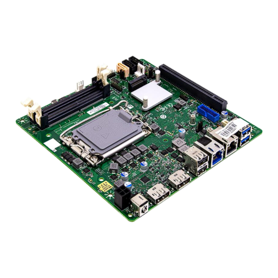
INS8367A User’s Manual V1.1 Revision Date: Sep. 01. 2023 1.3 Board Placement... -
Page 11: Chapter 2 : Jumpers And Connectors Loacation
INS8367A User’s Manual V1.1 Revision Date: Sep. 01. 2023 Chapter 2 : Jumpers and Connectors Location 2.1 Jumpers and Connectors List Label Function USB3.0 Header USB Header Intruder Header Front Panel Header SATA SATA Power Header SATA SATADOM COM1 COM2... -
Page 12: Jumper Setting
INS8367A User’s Manual V1.1 Revision Date: Sep. 01. 2023 2.2 Jumper Settings Front Panel Header DEFINITION DEFINITION 1 HDD_POWER_LED 2 POWER_LED_MAIN HDD_LED# POWER_LED_ALT POWER_SWITCH# RESET_SWITCH# +5V_DC Key(no pin) ATX Power Input Header PIN DEFINITION PIN DEFINITION DC12V_IN DC12V_IN TPM Header... - Page 13 INS8367A User’s Manual V1.1 Revision Date: Sep. 01. 2023 Debug : P2398 Card Header DEFINITION DEFINITION VCC (5V) Power Button PORT80_A 3VSB PORT80_B PORT80_E PORT80_C PORT80_F PORT80_D PORT80_G PORT80_DGH PORT80_DGL Dip switch_GPIO42 Dip switch_GPIO43 AT/ATX Mode Jumper DEFINITION AT Mode...
- Page 14 INS8367A User’s Manual V1.1 Revision Date: Sep. 01. 2023 Dual USB2.0 Header DEFINITION DEFINITION 5V_USB2_FP 5V_USB2_FP USB2_HR1_1N USB2_HR1_2N USB2_HR1_1P USB2_HR1_2P Key (no pin) No Connect Dual USB3.0 Header DEFINITION DEFINITION 5V_USB3_FP Key(no pin) USB3P4_RXN- 5V_USB3_FP USB3P4_RXP USB3P3_RXP USB3P3_RXP USB3P4_TXN_C- USB3P4_TXP_C...
- Page 15 INS8367A User’s Manual V1.1 Revision Date: Sep. 01. 2023 PEX8_16: PEX8 or PCIEX16 Select Header DEFINITION Pull High DFG[5]: PCI Express Bifurcation High: 1 x16 PCI Express* (Default) Low: 2 x8 PCI Express Pull Low DEFINITION Pins 1&2 closed: High: 1 x16 PCI Express* (Default) Pins 2&3 closed: Low: 2 x8 PCI Express...
-
Page 16: Chapter 3: Ami Bios Utility
INS8367A User’s Manual V1.1 Revision Date: Sep. 01. 2023 Chapter 3: AMI BIOS UTILITY This chapter provides users with detailed descriptions on how to set up a basic system configuration through the AMI BIOS setup utility. 3.1 Staring To enter the setup screens, perform the following steps: •... -
Page 17: Main Page
INS8367A User’s Manual V1.1 Revision Date: Sep. 01. 2023 3.3 Main Page Field Name BIOS Vender Default Value American Megatrends Comment This field is not selectable. There is no help text associated with it. Field Name Core Version Default Value 5.24... - Page 18 INS8367A User’s Manual V1.1 Revision Date: Sep. 01. 2023 Field Name BIOS Version Default Value Display the version of the BIOS Comment This field is not selectable. There is no help text associated with it Field Name Build Date Default Value...
- Page 19 INS8367A User’s Manual V1.1 Revision Date: Sep. 01. 2023 Field Name Serial ATA Port 4 Value Display the installed SATA device model/size of port 4. Comment This field is not selectable. There is no help text associated with it. Field Name...
-
Page 20: Advance Page
INS8367A User’s Manual V1.1 Revision Date: Sep. 01. 2023 3.4 Advance Page Field Name Onboard Device Help Onboard Device Configuration Comment Press Enter when selected to go into the associated Sub-Menu. Field Name CPU Configuration Help CPU Configuration Parameters Comment Press Enter when selected to go into the associated Sub-Menu. -
Page 21: Trusted Computing
INS8367A User’s Manual V1.1 Revision Date: Sep. 01. 2023 Field Name Trusted Computing Help Trusted Computing Settings Comment Press Enter when selected to go into the associated Sub-Menu. Field Name Super IO Configuration Help System Super IO Chip Parameters. Comment Press Enter when selected to go into the associated Sub-Menu. - Page 22 INS8367A User’s Manual V1.1 Revision Date: Sep. 01. 2023 3.4.1 Onboard Device Field Name DVT Total Gfx Mem Default Value [256M] Possible Value 128M 256M Help Select DVMT5.0 Total Graphic Memory size used by the Internal Graphics Device. Field Name...
- Page 23 INS8367A User’s Manual V1.1 Revision Date: Sep. 01. 2023 Field Name HD Audio Default Value [Enabled] Possible Value Enabled Disabled Help Control Detection of the HD-Audio device. Disabled = HDA will be unconditionally disabled Enabled = HDA will be unconditionally enabled.
- Page 24 INS8367A User’s Manual V1.1 Revision Date: Sep. 01. 2023 3.4.2 CPU Configuration Field Name Default Value Displays CPU Signature Comment This field is not selectable. There is no help text associated with it. Field Name Brand String Default Value Displays the CPU brand string Comment This field is not selectable.
- Page 25 INS8367A User’s Manual V1.1 Revision Date: Sep. 01. 2023 3.4.3 VMD setup menu Field Name VMD Configuration Default Value VMD Configuration. Comment This field is not selectable. There is no help text associated with it. Field Name Enable VMD controller...
- Page 26 INS8367A User’s Manual V1.1 Revision Date: Sep. 01. 2023 3.4.4 Trusted Computing Field Name FW Version Default Value TPM module version Comment This field is not selectable. There is no help text associated with it. Field Name Vender Default Value...
-
Page 27: Serial Port 1 Configuration
INS8367A User’s Manual V1.1 Revision Date: Sep. 01. 2023 Field Name Pending operation Default Value [None] Possible Value None TPM Clear Help Schedule an Operation for the Security Device. NOTE: Your Computer will reboot during restart in order to change State of Security Device. - Page 28 INS8367A User’s Manual V1.1 Revision Date: Sep. 01. 2023 Comment Press Enter when selected to go into the associated Sub-Menu. 3.4.6 Serial Port 1 Configuration Field Name Serial Port Default Value [Enabled] Possible Disabled Value Enabled Help Enable or Disable Serial Port(COM)
- Page 29 INS8367A User’s Manual V1.1 Revision Date: Sep. 01. 2023 Field Name Change Settings Default Value [AUTO] Possible Auto Value IO=3E8h; IRQ=7; IO=3E8h; IRQ=3,4,5,6,7,9,10,11,12; IO=2E8h; IRQ=3,4,5,6,7,9,10,11,12; IO=220h; IRQ=3,4,5,6,7,9,10,11,12; IO=228h; IRQ=3,4,5,6,7,9,10,11,12; Help Select an optimal settings for Super IO Device Field Name...
- Page 30 INS8367A User’s Manual V1.1 Revision Date: Sep. 01. 2023 3.4.7 Serial Port 2 Configuration Field Name Serial Port Default Value [Enabled] Possible Disabled Value Enabled Help Enable or Disable Serial Port(COM) Field Name Device Settings Default Value Device Super IO COM2 Address and IRQ.
-
Page 31: Hardware Monitor
INS8367A User’s Manual V1.1 Revision Date: Sep. 01. 2023 Field Name Change Settings Default Value [AUTO] Possible Auto Value IO=2E8h; IRQ=7; IO=3E8h; IRQ=3,4,5,6,7,9,10,11,12; IO=2E8h; IRQ=3,4,5,6,7,9,10,11,12; IO=220h; IRQ=3,4,5,6,7,9,10,11,12; IO=228h; IRQ=3,4,5,6,7,9,10,11,12; Help Select an optimal settings for Super IO Device 3.4.8 Hardware Monitor... - Page 32 INS8367A User’s Manual V1.1 Revision Date: Sep. 01. 2023 Type Range CPU Temperature -20 ~ (By Processor Tjmax)°C CPU VR Temperature -20 ~ 120°C CPU Fan Speed There are many kinds of the fan could be installed into the system, so we could only set 0 RPM for the failed fan speed, Front Fan Speed and there is also no high RPM limitation.
-
Page 33: S5 Rtc Wake Settings
INS8367A User’s Manual V1.1 Revision Date: Sep. 01. 2023 3.4.9 S5 RTC Wake Settings Field Name Wake system from S5 Default Value [Disabled] Possible Value Disabled Fixed Time Help Enable or disable System wake on alarm event, Select FixedTime, system will wake on the hr::min::sec specified. -
Page 34: Netword Stack Configuration
INS8367A User’s Manual V1.1 Revision Date: Sep. 01. 2023 Field Name Default Value Possible Value 0-59 Help Select 0-59 For Minute Field Name Default Value Possible Value 0-59 Help Select 0-59 For Second 3.4.10 Network Stack Configuration Field Name Network stack... -
Page 35: Nvme Configuration
INS8367A User’s Manual V1.1 Revision Date: Sep. 01. 2023 Enabled Help Enable/Disable UEFI Network stack. Field Name Ipv4 PXE Support (Available when Network stack Enabled) Default Value [Enabled] Possible Value Disabled Enabled Help Enable/Disable Ipv4 PXE Boot Support. If disabled IPV4 PXE boot support will not be available. -
Page 36: Security Page
INS8367A User’s Manual V1.1 Revision Date: Sep. 01. 2023 Field Name (Device) Comment Press Enter when selected to go into the associated Sub-Menu. 3.5 Security Page Field Name Administrator Password Help Set Administrator Password Field Name User Password Help Set User Password. -
Page 37: Hdd Security
INS8367A User’s Manual V1.1 Revision Date: Sep. 01. 2023 Comment Press Enter when selected to go into the associated Sub-Menu. Field Name BIOS Update Help BIOS Update support Comment Press Enter when selected to go into the associated Sub-Menu. 3.5.1 HDD Security... -
Page 38: Secure Boot
INS8367A User’s Manual V1.1 Revision Date: Sep. 01. 2023 3.5.2 Secure Boot Field Name Secure Boot Default Value [Enabled] Possible Value Enabled Disabled Help Secure Boot feature is Active if Secure Boot is Enabled,Platform Key(PK) is enrolled and the System is in User mode.The mode... -
Page 39: Key Management
INS8367A User’s Manual V1.1 Revision Date: Sep. 01. 2023 Secure Boot Policy variables can be configured by a physically present user without full authentication Field Name Restore Factory Keys Help Force System to User Mode. Install factory default Secure Boot key... - Page 40 INS8367A User’s Manual V1.1 Revision Date: Sep. 01. 2023 Field Name Factory Key Provision Default Value [Disabled] Possible Enabled Value Disabled Help Install factory default Secure Boot keys after the platform reset and while the System is in Setup mode...
- Page 41 INS8367A User’s Manual V1.1 Revision Date: Sep. 01. 2023 Field Name Key Exchange Keys Default Value Size:0, Keys:0, Key source: No Keys Help Enroll Factory Defaults or load certificates from a file: 1.Public Key Certificate: a)EFI_SIGNATURE_LIST b)EFI_CERT_X509 (DER) c)EFI_CERT_RSA2048 (bin) d)EFI_CERT_SHAXXX 2.Authenticated UEFI Variable...
- Page 42 INS8367A User’s Manual V1.1 Revision Date: Sep. 01. 2023 Field Name Forbidden Signatures Default Value Size:0, Keys:0, Key source: No Keys Help Enroll Factory Defaults or load certificates from a file: 1.Public Key Certificate: a)EFI_SIGNATURE_LIST b)EFI_CERT_X509 (DER) c)EFI_CERT_RSA2048 (bin) d)EFI_CERT_SHAXXX 2.Authenticated UEFI Variable...
- Page 43 INS8367A User’s Manual V1.1 Revision Date: Sep. 01. 2023 Field Name OsRecovery Signatures Default Value Size:0, Keys:0, Key source: No Keys Help Enroll Factory Defaults or load certificates from a file: 1.Public Key Certificate: a)EFI_SIGNATURE_LIST b)EFI_CERT_X509 (DER) c)EFI_CERT_RSA2048 (bin) d)EFI_CERT_SHAXXX 2.Authenticated UEFI Variable...
-
Page 44: Boot Page
INS8367A User’s Manual V1.1 Revision Date: Sep. 01. 2023 3.6 Boot Page Field Name Setup Prompt Timeout Default Value Possible Value 1~65535 Comment Number of seconds to wait for setup activation key. 65535(0xFFFF) means indefinite waiting. Field Name Bootup NumLock State... - Page 45 INS8367A User’s Manual V1.1 Revision Date: Sep. 01. 2023 Field Name Boot Option #1 Default Value [USB Floppy] Possible Value USB Floppy, CD/DVD, USB CD/DVD, Hard Disk , USB Key, USB Hard Disk , NVME, Network, Disabled Comment Sets the system boot order...
- Page 46 INS8367A User’s Manual V1.1 Revision Date: Sep. 01. 2023 Field Name Boot Option #7 Default Value [NVME] Possible Value USB Floppy, CD/DVD, USB CD/DVD, Hard Disk , USB Key, USB Hard Disk , NVME, Network, Disabled Comment Sets the system boot order...
-
Page 47: List Boot Device Type)Drive Bbs Priorites
INS8367A User’s Manual V1.1 Revision Date: Sep. 01. 2023 Comment Press Enter when selected to go into the associated Sub-Menu. Field Name (UEFI) USB Hard Disk Drive BBS Priorities Help Specifies the Boot Device Priority sequence from available Hard Disk Drives. -
Page 48: Save & Exit Page
INS8367A User’s Manual V1.1 Revision Date: Sep. 01. 2023 Help Sets the system boot order 3.7 Save & Exit Page Field Name Discard Changes and Exit Help Exit system setup without saving any changes. Field Name Save Changes and Reset Help Reset the system after saving the changes. -
Page 49: Event Logs
INS8367A User’s Manual V1.1 Revision Date: Sep. 01. 2023 3.8 Event Logs Field Name Change Smbios Event Log Settings Help Press <Enter> to change the Smbios Event Log configuration. Comment Press Enter when selected to go into the associated Sub-Menu. -
Page 50: Change Smbios Event Log Setting
INS8367A User’s Manual V1.1 Revision Date: Sep. 01. 2023 3.8.1 Change Smbios Event Log Setting Field Name Smbios Event Log Default Value [Enabled] Possible Value Enabled Disabled Help Change this to enable or disable all feature of Smbios Event Logging during boot. -
Page 51: View Smbios Event Log
INS8367A User’s Manual V1.1 Revision Date: Sep. 01. 2023 Field Name Whea Log is Full Default Value [Do Nothing] Possible Value Do Nothing Erase Immediately Help Choose options for reactions to a full Smbios Event Log. 3.8.2 View Smbios Event Log...
Need help?
Do you have a question about the INS8367A and is the answer not in the manual?
Questions and answers