JVC GY-HC900CHE Instructions Manual
Hd memory card camera recorder
Hide thumbs
Also See for GY-HC900CHE:
- Instructions manual (52 pages) ,
- Instructions manual (236 pages)
Table of Contents
Advertisement
Quick Links
.
HD MEMORY CARD CAMERA RECORDER
GY-HC900CHU/GY-HC900CHE
GY-HC900STU/GY-HC900RCHE
INSTRUCTIONS
.
.
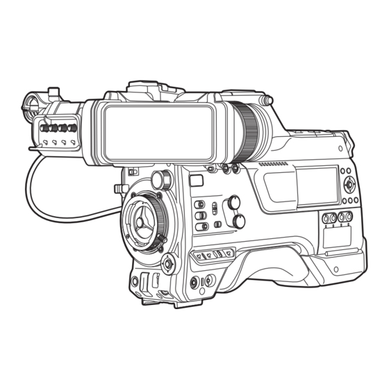
In this illustration, the supplied viewfinder is attached to the GY-HC900CHU/GY-HC900CHE.
Wireless LAN antenna and viewfinder are not included in GY-HC900STU and GY-HC900RCHE.
The specifications and appearance of this product are subject to changes for further improvement
without prior notice.
Please check the latest version of the INSTRUCTIONS from the following Mobile User Guide. You can
also download the PDF from the Mobile User Guide.
Mobile User Guide
When you are outside, you can refer to the instructions from your Android phone or iPhone.
http://manual3.jvckenwood.com/pro/mobile/global/
You can view the Mobile User Guide using the browser on your Android phone or iPhone.
For Customer Use:
Enter below the Serial No. which is located
on the body.
Retain this information for future reference.
Model No.
GY-HC900CHU/GY-HC900STU
Serial No.
IM 2.07
Please read the following before getting started:
Thank you for purchasing this product.
Before operating this unit, please read the
instructions carefully to ensure the best
possible performance.
In this manual, each model number is
described without the last letter (U/E) which
means the shipping destination.
(U: for USA and Canada, E: for Europe)
Only "U" models (GY-HC900CHU/
GY-HC900STU) have been evaluated by UL.
B5A-2755-10
Advertisement
Table of Contents

Related Manuals for JVC GY-HC900CHE


Summary of Contents for JVC GY-HC900CHE
- Page 1 GY-HC900CHU/GY-HC900CHE GY-HC900STU/GY-HC900RCHE INSTRUCTIONS In this illustration, the supplied viewfinder is attached to the GY-HC900CHU/GY-HC900CHE. Wireless LAN antenna and viewfinder are not included in GY-HC900STU and GY-HC900RCHE. The specifications and appearance of this product are subject to changes for further improvement without prior notice.
- Page 3 FOR USA These are general Important Safety Instructions and certain items may not apply to all appliances. Important Safety Instructions Read these instructions. Keep these instructions. Heed all warnings. Follow all instructions. Do not use this apparatus near water. Clean only with dry cloth. Do not block any ventilation openings.
- Page 4 POUR LES ÉTATS-UNIS Ces informations sont des CONSIGNES DE SÉCURITÉ IMPORTANTES et certains points peuvent ne pas s’appliquer à tous les appareils. CONSIGNES DE SÉCURITÉ IMPORTANTES Lire ces instructions. Conserver ces instructions. Tenir compte de tous les avertissements. Respecter toutes les instructions. Ne pas utiliser cet appareil à...
-
Page 5: Safety Precautions
Safety Precautions POUR CANADA FOR USA AND CANADA ATTENTION RISQUE CAUTION D’ELECTROCUTION NE PAS OUVRIR RISK OF ELECTRIC SHOCK ATTENTION: DO NOT OPEN POUR EVITER TOUT RISQUE CAUTION: D’ELECTROCUTION NE PAS OUVRIR LE BOITER. AUCUNE TO REDUCE THE RISK OF PIECE INTERIEURE N’EST A ELECTRIC SHOCK. - Page 6 Changes or modifications not Des changements ou modifications approved by JVC could void the non approuvés par JVC peuvent user’s authority to operate the annuler le droit de l’utilisateur de faire equipment. This equipment has been fonctionner l’appareil.
- Page 7 CAUTION: Attention: The mains plug shall remain readily La prise secteur doit être opérationnelle. operable. Débranchez immédiatement la fiche Remove the mains plug immediately if secteur si le caméscope ne fonctionne the camera functions abnormally. pas normalement. WARNING: Avertissement: The battery pack, the camera with Évitez d’exposer la batterie, le battery installed, and the remote control caméscope avec la batterie insérée ou la...
- Page 8 When the equipment is installed in a Si le matériel est installé dans un coffret cabinet or on a shelf, make sure that it ou sur une étagère, s’assurer qu’il y a un has sufficient space on all sides to allow espace suffisant sur tous les côtés pour for ventilation (10 cm (3-15/16") or more permettre la ventilation (10 cm (3-15/16")
- Page 9 IMPORTANT (for owners in the U.K.) CAUTION: Connection to the mains supply in Where there are strong electromagnetic the United Kingdom. waves or magnetism, for example near a radio or TV transmitter, transformer, DO NOT cut off the mains plug from motor, etc., the picture and the sound this equipment.
- Page 10 Normen bezüglich elektromagnetischer Verträglichkeit überein. Hereby, JVCKENWOOD Corporation declares that the radio equipment type GY-HC900CHE is in compliance with Directive 2014/53/EU. The full text of the EU declaration of conformity is available at the following internet address: Hiermit erklärt die , JVCKENWOOD...
-
Page 11: Table Of Contents
Contents Switching the SD cards ........ 50 Inserting the SSD Media Adapter (Sold Separately) ..........50 Introduction Formatting (Initializing) of Recording Media . 51 Safety Precautions ..........5 Repairing the Recording Media ....52 Contents ............11 Clips Recorded to Recording Media .... 53 Main Features .......... - Page 12 Playback Display/Status Screen Playing Recorded Clips ........97 Display Screen in Camera Mode ....170 Thumbnail Screen ........97 Display Screen in Media Mode ...... 176 Actions ............99 Status Screen ..........179 Playing back ..........100 Camera Features Deleting Clips ..........102 Marker and Safety Zone Displays (Camera Mode Appending/Deleting OK Mark ......
- Page 13 Changing Connection Setup ...... 215 Changing Metadata Server Settings ..216 Changing Clip Server Settings ....216 Changing Streaming Settings ....216 Managing the Network Connection Settings File ............... 217 Saving the Connection Settings File ..217 Reading the Connection Settings File ..218 Deleting Connection Settings ....
-
Page 14: Main Features
Main Features Newly developed user multi-matrix for 16-axis color correction In addition to the conventional 6-axis user linear matrix adjustment, this camera recorder is A variety of wired and wireless equipped with user multi-matrix that enables interfaces to support various network accurate adjustment of hue and saturation in the connections smaller 16-axis color region. - Page 15 UniSlot is a registered trademark of Ikegami : Feature available on GY-HC900CHU Tsushinki Co., Ltd. only. Other product and company names included in : Feature available on GY-HC900CHE this instruction manual are trademarks and/or only. registered trademarks of their respective : Feature available on GY-HC900STU companies.
-
Page 16: Precautions For Proper Use
Precautions for Proper Drip-proof o This camera recorder has a drip-proof structure equivalent to IPX2 according to our testing method. It is not completely waterproof. And the drip-proof performance under all conditions is not guaranteed. Storage and Usage Locations IPX2 (protection rating against dripping water) o Allowable ambient temperature and humidity ensures that when a device is tilted at an angle Be sure to use this unit within the allowable... - Page 17 Rechargeable Battery Lens o The batteries recommended for use with this o This camera recorder is an interchangeable lens camera recorder are as follows. camera. Please have the interchangeable lens U model : Digital 150 (Anton/Bauer) ready before use. E model : DUO-C198, DUO-C98 (IDX) o Read the “INSTRUCTIONS”...
- Page 18 o Do not use pencils or ballpoint pens to write on SDHC/SDXC Cards the SD cards. Always use oil-based pens. o SDHC/SDXC card is referred to as “SD card” or o If you format (initialize) the SD card, all data “recording media”...
- Page 19 License Notices Others o MPEG LA AVC o Do not insert objects other than the memory card THIS PRODUCT IS LICENSED UNDER THE into the card slot. AVC PATENT PORTFOLIO LICENSE FOR o Do not block the vent on the unit. THE PERSONAL USE OF A CONSUMER OR Blocking of the vent causes internal heating and OTHER USES IN WHICH IT DOES NOT...
-
Page 20: Operation Modes
Operation Modes This camera recorder has three operation modes - Camera mode, Media mode, and Remote Edit mode. Camera Mode Media Mode [CANCEL/RESET]/[MENU/THUMB] Button Press and hold [CAM/MEDIA] Playback Camera Input Thumbnail Display Normal Playback [SET] Button (R) [CAM/MEDIA] Trimming Playback Execute Button [Trim This Clip]... - Page 21 Operation Mode Description Camera Mode This is the camera shooting mode. The camera recorder starts up in Camera mode when the power is turned on. Camera images are output to the viewfinder and LCD monitor. When a recordable media is inserted, the camera recorder enters the recording standby mode. “STBY” appears on the operation mode display area of the LCD monitor and viewfinder.
-
Page 22: Names Of Parts
Names of Parts H I J A Speaker H [MIC LEVEL] Knob For manual adjustment of the recording level for (A P100 [Audio Output during Playback] ) the microphone that is attached to the [MIC IN] B Viewfinder Left-Right Position Lock Ring terminal when the [AUDIO SELECT For loosening the ring and adjusting the position CH1/2/3/4]-[MANUAL/AUTO] selection switch... - Page 23 L Slide Cover (For [USER6]/[USER7] Button) V Shoulder Belt Mount (x2) Sliding the cover over the buttons helps to For mounting a shoulder belt (sold separately). prevent accidental operation. Caution : M [USER6] Button Be sure to use a shoulder belt with the strength It can be assigned with a specific menu function.
-
Page 24: Side Control Panel
Side Control Panel G [USER3] Button It can be assigned with a specific menu function. (A P45 [Assignment of Functions to User Buttons] ) H [USER0] Switch It can be assigned with a specific menu function. (A P45 [Assignment of Functions to User Buttons] ) I [GAIN H/M/L] Switch For selecting the gain sensitivity level. - Page 25 P [AUDIO INPUT CH1/2/3/4] Recording Level U [TC PRESET] Button Adjustment Knob When the [TC GEN] switch is set to “F-RUN” or For adjusting the recording level manually when “R-RUN”, this camera recorder enters or exits the [MANUAL/AUTO] selection switch is set to Preset mode when this button is pressed.
-
Page 26: Side Terminal Section
Side Terminal Section a [MENU/THUMB] Button Displays the menu screen during Camera mode. Switches between [Main Menu] and [Favorites Menu] when the [MENU/THUMB] button is pressed and held down while the menu screen is displayed. (A P107 [Basic Operations in Menu Screen] ) Displays the menu screen when the button is pressed during thumbnail display in the Media mode. -
Page 27: Rear Terminal
Rear Terminal H [HD/SD SDI OUT1/2] Terminal (A P188 [Connecting External Monitor] ) I [HD/SD SDI IN] Terminal (A P191 [Inputting External Synchronizing Signals (Genlock)] ) J [REMOTE] Terminal (A P189 [Connecting a Remote Control Unit] ) K [DC OUT] (LAN) Terminal Supplies power to devices such as a mobile router that is connected to the [LAN] terminal. -
Page 28: Electronic Viewfinder U V
Electronic Viewfinder u v L [ZEBRA] Switch Displays the zebra pattern. (A P42 [Adjusting the Viewfinder] ) ON: Turns on zebra pattern; OFF: Turns off zebra pattern; MOMENT: “Turns on zebra pattern” for a specific time interval while the switch is being pressed. M [TALLY] Front Tally Switch For configuring the front tally lamp. -
Page 29: Basic System Diagram
Basic System Diagram Shoulder Belt Wireless Microphone Video Light Camera Receiver Recorder Headphone [LIGHT] [SDI OUT] SDI Cable BNC Microphone [MIC IN] Composite Monitor Cable BNC Focus Manual Controller [AUDIO Audio cable XLR INPUT HZ-FM13(FUJINON) [PHONE] [SDI IN] 1/2] HDMI Cable HZ-FM15(CANON) Zoom Servo Monitor... -
Page 30: Settings And Adjustments Before Use
Settings and Adjustments Attaching the Viewfinder (Supplied) Before Use Attaching the Lens (Sold Separately) This camera recorder can be attached with a B4 mount lens. Caution : Check that the camera recorder is turned off before attaching the lens. Attaching the lens with the power turned on can result in accident and malfunction. -
Page 31: Attaching The Microphone (Sold Separately)
Attaching the Microphone (Sold Attaching the Video Light (Sold Separately) Separately) You can attach a separately sold microphone to the Video lights or accessories can be attached to the microphone holder. accessory shoe of this camera recorder. The microphone that is sold separately uses a The accessory shoe is of the 1/4-inch screw type. -
Page 32: Attaching The Wireless Lan Antennas
Attaching the Wireless LAN Antennas Adjusting the Position of the Shoulder (Supplied) u v Adjust the position of the shoulder pad back and Attach the wireless LAN antenna by turning it in the forth. clockwise direction. Hold the base while attaching the antenna. -
Page 33: Power Supply
Power Supply Using AC Power (DC IN Power) Use the AC adapter (sold separately) to operate the camera recorder with AC power. To use this camera recorder, you can attach a battery pack or connect an AC adapter to it. Recommended AC Adapter (A P34 [Using a Battery Pack] ) (A P33 [Using AC Power (DC IN Power)] ) -
Page 34: Using A Battery Pack
Precautions for the Battery Operation Using a Battery Pack Do not remove the battery when the [POWER Recommended Batteries ON/OFF] switch is “ON”. Do not insert or remove the DC cable when the U model : Digital 150 (Anton/Bauer) battery is in use. E model : DUO-C198, DUO-C98 (IDX) Leaving the camera recorder unused with the * Models with an E suffix are for the European... -
Page 35: Battery Warning Settings
Attaching/Detaching the Battery (E Model) Battery Warning Settings Use the following battery type. Follow the steps below to configure the warning V Mount voltage or warning level when the remaining battery level is running low. 1 Attach the battery. Face the terminal downward and attach the V 1 Select “Voltage”... -
Page 36: Power Status Display
Power Status Display Menu Screen (A P108 [Display and Description of the Menu Screen] ) Viewfinder Screen and LCD Monitor The power status is displayed on the display and menu screens. Display Settings Display Description Currently powered by a battery. B 14.4V When the battery power runs out, B 100min... -
Page 37: Turning On/Off The Power
Turning On/Off the Power Turning Off the Power Sets the camera recorder to the recording standby or stop mode. Turning On the Power 1 Set the [POWER ON/OFF] switch to “OFF”. 2 Remove the battery and the power to the [DC INPUT] terminal (when not in use for a long time). -
Page 38: Initial Settings
Initial Settings Memo : The menus and messages on the screen of the When the power is first turned on, the Initial Setting LCD monitor or viewfinder are displayed in the screen for performing the initial settings in the selected language. camera recorder appears. - Page 39 Changing the Time after Initial Setting 4 Press the [STATUS/SET] button (R) after confirming the exit screen. Setting the Date/Time The [Date/Time] screen appears. (A P158 [ Date/Time ] ) For U models 1 Select [System] B [Date/Time]. The [Date/Time] screen appears. 2 Set the date and time.
-
Page 40: Displays On The Lcd Monitor And Viewfinder
Displays on the LCD Display Screen (VF/LCD) in Media Mode (A P176 [Display Screen in Media Mode] ) Monitor and Viewfinder This is the screen display during clip playback in Media Mode. The display switches with every press of the You can display the camera status, recording [DISPLAY] button. -
Page 41: Status Screen
Status Screen Remote Edit Mode Screen This screen allows you to check the current This is a mode for accessing the page for editing settings. the metadata that is recorded in a clip via a web To display the status screen, press the browser on devices such as a smartphone, tablet [STATUS/SET] button in the normal screen. -
Page 42: Adjusting The Lcd Monitor And Viewfinder
Adjusting the LCD Monitor Adjusting the Viewfinder and Viewfinder You can change the brightness and peaking of the viewfinder screen according to your usage conditions. You can monitor video images on this camera Changing the brightness of the screen will not recorder using the viewfinder, LCD monitor, or affect the recorded images. - Page 43 o Flipping up the Eyepiece 5 Adjust the brightness, outline and contrast Flipping up the eyepiece provides a better view of the viewfinder screen. of the entire image. Push the lock upward to flip up the eyepiece. Adjusting the Brightness Use the [BRIGHT] knob to adjust the brightness of the viewfinder.
-
Page 44: Adjusting The Back Focus
Adjusting the Back Focus When the lens is attached for the first time, adjust the back focus of the lens if the focus is not clear when it is zoomed to the telephoto or wide-angle end. The Siemens Star Chart is most suitable as the subject. -
Page 45: Assignment Of Functions To User Buttons
Assignment of Functions to User Buttons You can assign functions to the following buttons and use them as user buttons. By assigning functions to the buttons, the usability of the camera recorder can be enhanced. Perform settings in the menu items corresponding to each button. -
Page 46: Tally Lamp
Tally Lamp When [Tally System] is set to “Internal” Front Tally/ Back Tally Menu Setting This is the indicator lamp for recording and Live Rec/Live warning. Streaming Streaming The operation changes according to the menu Information Warning settings. on Camera The lamp blinks when the battery or remaining Alarm Recorder... -
Page 47: Recording Media
Recording Media Usable SSD Media Refer to the “Instruction Manual” of the SSD Media Adapter that is inserted into the expansion slot to This camera recorder saves recorded audio sound mount a compatible SSD media. and videos except those in “HD EXT(SSD)” quality to the SD card (sold separately) in the card slot. -
Page 48: Estimated Recordable Time Of Ssd Media
Estimated Recordable Time of SSD System Media QuickTime (MPEG2), Exchange, Format MXF (MPEG2) MP4 (H.264) The estimated recordable time is only a guide. Differences may occur depending on the SSD 1920x1080, media in use and condition of the battery. Resolution 1440x1080, 1440x1080 1920x1080 1280x720 The recordable time varies according to the... -
Page 49: Inserting An Sd Card
Inserting an SD Card Removing the SD Card This camera recorder comes with two card slots 1 Check that the SD card to be removed is not (Slot A and B) for video/audio recording and being accessed (status indicator of the playback. -
Page 50: Switching The Sd Cards
Switching the SD cards Inserting the SSD Media Adapter (Sold Separately) When both card slots are inserted with SD cards, you can use the [SLOT SELECT] button to switch This unit is equipped with an [expansion slot] for the card to use. recording and playing back video and audio in the When the memory on an SD card is full during “HD EXT(SSD)”... -
Page 51: Formatting (Initializing) Of Recording Media
Formatting (Initializing) of Recording 4 Select [Format] and press the Media [STATUS/SET] button (R). When any of the following recording media (SD card or SSD media) is inserted, [!FORMAT] appears in the remaining level display area. Format Media Format the card using the camera recorder menu. Unformatted recording media Recording media formatted under different specifications... -
Page 52: Repairing The Recording Media
Repairing the Recording Media 4 Restoring is complete. It is necessary to restore the recording media if an When restoring is complete, “Complete” abnormality occurs to the data in the recording appears and the camera recorder returns to the media due to some reasons. [Restore Media] screen. -
Page 53: Clips Recorded To Recording Media
Example: QuickTime Clips Recorded to Recording Media Folders Created in the Recording Media A B C G0 0 0 1 The captured image is recorded into different Clip Number folders according to the [Format] settings. A number in automatic Other than MXF (MPEG2): [DCIM] ascending order is assigned in MXF (MPEG2): [PRIVATE] the recording order. -
Page 54: Operation Lock Feature
Operation Lock Feature Operation lock does not apply to the following buttons and switches. [POWER ON/OFF] switch You can use this feature to prevent erroneous [ND FILTER] switch camera operation. [MONI SELECT] switch [CH SELECT] switch [AUDIO INPUT CH1/2/3/4] recording level adjustment knob [AUDIO SELECT CH1/2/3/4]-[MANUAL/AUTO] selection switch... -
Page 55: Shooting
Basic Shooting Shooting Procedures 1 Configure the video and audio input settings. You have to configure video settings such as Preparations brightness adjustment (iris, gain, shutter) and white balance adjustment in order to start shooting. You also have to adjust the audio input settings and audio recording level for audio recording. -
Page 56: Selecting System Definition, File Format And Video Format
Selecting System You can select a definition for the recorded images from the following items under [System]. Definition, File Format and HD EXT(SSD): Records to the expansion slot in the HD EXT Video Format quality. Records in HD quality for both slots A and B. You can select the definition of the recorded Records in SD quality for both slots A and B. - Page 57 o When [System] is configured to “HD”, “HD Selecting a File Format +Web” or “HD(SDI In)”, the options for slot A are: Select a file format in [WFormat]/[YFormat]. Record Format The following file formats are available for W Format W Frame W Bit Rate W Audio selection.
- Page 58 o When [System] is set to “High-Speed” o When [System] is set to “SD” or “SD(SDI In)”: Record Format Record Format W Format W Frame W Bit Rate W Audio W Format W Frame W Bit Rate W Audio Resolution Resolution Rate Rate...
-
Page 59: Zoom Operation
Zoom Operation Focus Operation Adjusts the angle of view. Zooming can be operated using the following. Adjusting the Focus Zoom ring/zoom lever on the commercially available lens 1 Turn the focus ring to adjust the focus. User buttons assigned with “Zoom Tele” and Memo : “Zoom Wide”... -
Page 60: Adjusting The Brightness
Adjusting the Brightness Expanded Focus Function You can magnify the preferred area by pressing the user button assigned with “Expanded Focus”; Adjust the brightness using Iris, Gain, Shutter doing so enables precise focus to be established speed and ND filter according to the brightness of easily. -
Page 61: Adjusting The Iris
Adjusting the Iris Memo : Using the user button assigned with “Full Auto” to enter the Full Auto mode also activates the Adjust the aperture of the lens iris according to the automatic brightness adjustment (AE) mode. In brightness of the subject. this case, the White Balance also enters into Auto mode forcibly. -
Page 62: Setting The Gain
Setting the Gain Auto Iris (Automatic Adjustment) Mode 1 Set Full Auto mode to off using the user button assigned with “Full Auto”. This function electrically boosts the light sensitivity when there is insufficient illumination on the object. 2 Set to Auto Iris mode using the [IRIS A/M] You can set the gain of the video amplifier switch on the lens. -
Page 63: Setting The Electronic Shutter
Setting the Electronic Automatic Gain Mode (Automatic Gain Adjustment) Shutter 1 Set Full Auto mode to off using the user button assigned with “Full Auto”. You can change the shutter speed (time for each 2 Set [Camera Function] B [GAIN L]/[GAIN shooting frame) using the electronic shutter M]/[GAIN H] to “AGC”. - Page 64 After the shutter speed indication turns white, the Automatic Shutter Mode (Automatic setting value can be changed using the cross- Shutter Adjustment) shaped button (JK). 1 Set Full Auto mode to off using the user You can use the cross-shaped button I to switch button assigned with “Full Auto”.
-
Page 65: Adjusting The White Balance
Adjusting the White Memo : Balance Use the user button assigned with “Full Auto” to enter the Full Auto mode also activates the Automatic White Balance mode. In this case, the Iris, Gain and Shutter also enter into Auto mode Adjust the white balance according to the color forcibly. - Page 66 Setting the [Preset Temp.] or [Alternative 3 Press the Set button (R). Temp.] Values Returns to the [White Balance] screen. You can change both the color temperature settings in the Preset mode in the menu. White Balance 1 Open the [Preset Temp.] or [Alternative Temp.] menu.
- Page 67 Preset Paint Adjustment 4 Locate a place with similar lighting conditions as the object to be shot, place a white object The white balance for [Preset Temp.] and near the center of the screen and zoom in to [Alternative Temp.] can be fine adjusted fill the screen with white.
- Page 68 Error Message 3 Press the Set button (R). If the Auto White Balance adjustment is not Returns to the [White Balance] screen. correctly completed, one of the following messages will appear for about 3 seconds. Message Status White Balance Auto White * NG: Displayed when there is not R Value Object...
- Page 69 Adjusting the Vertical Shading Vertical Shading Adjustment Adjustment of white shading is needed when 1 Set [Camera Process] B [White Balance] B you have changed the lens. [V. Shading] to “On”. Although white balance may be appropriate at 2 Select [Adjust...] in [V. Shading] and press the center of the image, this may not be the case the Set button (R).
-
Page 70: Adjusting The Camera Image
Adjusting the Camera Memo : There may be some delay in the changes of the Image evaluated value after pressing the cross-shaped button (JK). Increasing the setting value suppresses the The picture quality of the camera can be set using colors at the bottom and enhances the colors on the [Camera Process] menu. -
Page 71: Audio Recording
Audio Recording When the switch setting is set to “FRONT” Audio recording is performed according to the setting in [A/V Set] B [Audio Set] B [Front Mic You can record audio from the four channels (CH1/ Select]/[Front Mic Power]/[Front Mic 1 Ref.]/[Front CH2/CH3/CH4) in synchronization with the video Mic 2 Ref.]. - Page 72 Manual Adjustment Mode (Manual “UniSlot” Adjustment) Wireless Camera Receiver The manual adjustment mode is enabled by setting the [AUDIO SELECT CH1/2/3/4]- Single: CH1/CH2 [MANUAL/AUTO] selection switch on this Dual: camera recorder to “MANUAL”. The audio level for each channel can be configured in [A/V Set] B [Audio Set] B [CH1 Audio Level](/2/3/4) B Caution : [Front]/[Rear/Wireless].
- Page 73 Memo : The [Threshold Level], [Attack Time], [Decay Time], [Mode], etc. of the compressor can be configured in [A/V Set] B [Audio Set] B [CH1/2 DRC]/[CH3/4 DRC] for the audio to be recorded. * DRC (Dynamic Range Compressor) The limiter operates according to the setting in [A/V Set] B [Audio Set] B [Limitter] B [CH1](/ 2/3/4).
- Page 74 References on DRC (Dynamic Range [CH1/2 DRC] and [CH3/4 DRC] settings Compressor) and Limiter Threshold : This is the point when the gain Level changes slowly. (See Figure 1) DRC and Limiter Configuration Block Diagram Lowering the threshold level will make it difficult for the recording level to become saturated but this On/Off...
-
Page 75: Audio Output During Recording
Audio Output during Time Code and User’s Bit Recording Time code and user’s bit data are recorded with the video in this camera recorder. You can check the recorded audio from the The time code and user’s bit are displayed on the monitor speaker or the headphone connected to viewfinder and LCD monitor during playback or the [PHONE] terminal. -
Page 76: Setting Time Code Generator
Setting Time Code Time Code Operation Mode Generator Select the time code operation using the [TC GEN] switch. Setting Description Presetting the Time Code F-RUN The time code operates in the run mode at all times regardless of the Time code and user’s bit data generated from the recording status. - Page 77 Setting Time Code 2 Select the framing mode for the time code generator (only when the frame rate setting 1 Select [TC/UB] B [TC Preset] and press the is “60” or “30”). Set button (R). To configure the setting, go to [TC/UB] B [Drop (A P126 [ TC Preset ] ) Frame].
- Page 78 Setting Time Code without Opening the 5 Check the values and press the Set button Menu (R). The time code is set and the screen returns to the normal screen. To cancel the setting, press the [TC PRESET] button. Caution : When the camera recorder is switched to Media PRESET mode during editing, editing will be canceled...
-
Page 79: Setting The User's Bit
Setting the User’s Bit 2 Select [TC/UB] B “Preset” and press the Set button (R). The [Preset] setting screen appears. You can add the date, time or an 8-digit hexadecimal number as the user’s bit to the 3 Use the cross-shaped button (HI) to place recorded image. -
Page 80: Synchronizing The Time Code With An External Time Code Generator
Synchronizing the Time Setting User’s Bit without Opening the Menu Code with an External Time Code Generator This camera recorder comes with a [TC IN] terminal. Connect a time code signal generator to the [TC PRESET IN] terminal to synchronize with the SMPTE/EBU LTC time code. - Page 81 Settings and Operation of the Camera 1 Input the external synchronizing signal to Recorder the external time code generator and the [GENLOCK] terminal of this camera 1 Set to Camera mode. recorder. (A P20 [Operation Modes] ) Memo : 2 Set [A/V Set] B [Video Set] B [Genlock BB signals or HDTV tri-level synchronizing Input] to “GENLOCK”.
-
Page 82: Setting Zebra Pattern
Setting Zebra Pattern Memo : When [Zebra] is set to “1 Pattern”, “Top 2” and When the luminance level range for displaying “Bottom 2” cannot be selected. zebra patterns is specified, diagonal lines (zebra If the area specified by two zebra patterns pattern) are displayed at areas with the specified overlaps, Zebra1 pattern will be displayed. -
Page 83: Setting Spot Meter
Setting Spot Meter Color of Frame Item Settings Indicating the The brightness of the object during shooting is Position displayed. Max & Min Displays the Max: Green This function is useful when setting video or stage brightness (%) Min: Yellow lighting or when specifying camera exposure. - Page 84 When [Max & Min]/[Max]/[Min] is selected When [Manual] is selected A The cursors appear according to the setting A The brightness of the cursor position is when the button is pressed. displayed when the button is pressed. Green and yellow frames appear, and the brightness levels of these areas are displayed.
-
Page 85: Acquiring Positioning Information By Gps V U
Acquiring Positioning Reception Display Positioning Status Information by GPS v Status GPS reception Receiving strong in progress GPS signal. UTC (signal strength: and positioning strong) information can be This camera recorder comes with a built-in GPS obtained and function. The GPS function is able to record the recorded. -
Page 86: Viewing Recorded Videos Immediately (Clip Review)
Viewing Recorded Videos Caution : Immediately (Clip Review) During Clip Review, only the [CANCEL/RESET] and [REC] buttons are enabled. Press the [CANCEL/RESET] button to cancel clip review and return to “STBY” (recording You can check (review) the last recorded video clip standby) mode. -
Page 87: Displaying The Video Signal Monitor
Displaying the Video o When the upper limit is set to 110% and the lower limit to 0% Signal Monitor The video signal monitor can be displayed using the user button assigned with “Video Signal Monitor”. The display operation functions according to the setting in [Camera Function] B [User Switch Set] B [Video Signal Monitor]. -
Page 88: Recording Simultaneously At Two Different Definitions
Recording Dual Rec Simultaneously at Two If both the slots are loaded with recordable cards Different Definitions in the Dual Rec mode ([Slot Mode] is set to “Dual”), pressing the [REC] button starts recording simultaneously to the media in both By setting [System] to “HD+Web”, you can record the slots. - Page 89 Caution : 2 Start recording. To perform recording in the Dual Rec mode, it is Insert recordable media in both slots, and recommended that you start recording by press the [REC] button. making use of two cards with the same capacity In the Dual Rec mode, recording to the media and from the formatted state.
-
Page 90: Backup Rec
Backup Rec 1 Set [System] B [Record Set] B [Slot Mode] to “Backup Y” or “Backup ”. Backup Rec mode enables backup recording to (A P164 [ Slot Mode ] ) the media in Slot B or the expansion slot by “BACKUP”... - Page 91 3 Start normal recording (normal recording 5 Stop backup recording. into slot A). Select [STBY] in [System] B [Record Set] B Press any of the [REC] buttons. [Slot Mode] B [Backup Rec] and press the Recording into the media in slot A starts. Set button (R).
-
Page 92: Special Recording
Special Recording Completed Clip (Recorded video and audio) Besides the normal recording mode, four special recording methods are available in this camera recorder. They are Pre Rec, Clip Continuous, Frame Rec and Interval Rec. Select a mode from [System] B [Record Set] B Recording starts a [Rec Mode]. -
Page 93: Clip Continuous Rec
Clip Continuous Rec 3 Pause recording. Press the [REC] button again to pause In normal recording, when the recording stops, the image, audio, and accompanying data from recording. The display changes (“RRECC” the start till the end of the recording are recorded B “STBYC”... -
Page 94: Frame Rec
Frame Rec Memo : The following operations cannot be performed In normal recording, when the recording stops, the while recording is paused (STBYC, yellow text). image and accompanying data from the start till the Clip Review operation end of the recording are recorded as one “clip” on (A P86 [Viewing Recorded Videos the SD card. -
Page 95: Interval Rec
Interval Rec 2 Set the number of frames to record in [Rec Frames]. In normal recording, when the recording stops, the To configure the setting, go to [System] B image and accompanying data from the start till the end of the recording are recorded as one “clip” on [Record Set] B [Rec Mode] B [Rec Frames]. -
Page 96: Splitting The Clips Freely (Clip Cutter Trig)
Splitting the Clips Freely 3 Set the time interval to start recording in (Clip Cutter Trig) [Interval Rec]. To configure the setting, go to [System] B [Record Set] B [Rec Mode] B [Rec Interval]. You can split the clips freely without having to stop (A P163 [ Rec Interval ] ) recording during shooting. -
Page 97: Playing Recorded Clips
Playing Recorded Clips F [USER3] Button Switches the selection status of the clip selected by the cursor. To play back clips recorded on SD cards, switch to Clips being selected are displayed with the Media mode. check mark. Press and hold the [CAM/MEDIA] selection button G [USER4] Button in the Camera mode to enter the Media mode. - Page 98 Memo : Memo : Dependent on the settings for [System] B Clips appended with OK marks cannot be [Record Set] B [Record Format] B [System]/ deleted on the camera recorder. [WResolution]/[YResolution]/[WFrame Rate]/ B Continued From Mark [YFrame Rate]/[WBit Rate], and [YBit Rate]. (A P160 [ System ] ) This mark indicates that the current clip is continued from another SD card when...
-
Page 99: Actions
Detailed screen Actions * Items that are common with the Standard screen The action selection screen is displayed when the will not be described. Refer to “[Standard [USER4] button is pressed. screen] (A P 97)”. The following operations can be performed. Item Description Select All Clips Selects all clips. -
Page 100: Playing Back
Playing back Item Description FTP Upload Uploads a clip to the FTP server. Use the operation buttons on the side control panel This Clip: of the camera recorder to play back. Uploads the clip pointed by the cursor. Selected Clips: Uploads the clips selected (appended with check mark). - Page 101 Time Code Playback Time code or user’s bit recorded on an SD card can be displayed on the LCD monitor and viewfinder. Memo : The time code is also superimposed on the video signal output from the [HD/SD SDI OUT 1/2] terminal.
-
Page 102: Deleting Clips
Deleting Clips 4 Select [Delete] using the cross-shaped button (JK), and press the Set button (R). Deleting starts. Delete clip. Memo : Clips appended with OK marks cannot be deleted on the camera recorder. Read-only clips can be deleted on a PC. Delete This Clip? Delete Deleting One Clip... -
Page 103: Appending/Deleting Ok Mark
Appending/Deleting OK During Playback or Pause Screen Mark 1 Press [USER1] button during clip playback. If the clip does not have an OK mark, an OK mark will be appended. If the clip is appended with an OK mark, the You can append OK marks to the clips for OK mark will be deleted. -
Page 104: Selecting And Performing Operations On Multiple Clips
Selecting and Performing Selecting Multiple Clips Randomly Operations on Multiple 1 Move the cursor to a clip without a check mark, and press the [USER3] button. Clips A green check mark appears on the clip. Multiple clips can be selected during thumbnail screen or playback screen display. -
Page 105: Selecting Multiple Clips Consecutively
Selecting Multiple Clips Consecutively 5 Press the Set button (R) to confirm the range. 1 Press the [USER4] button. The check marks change from magenta to 2 Select “Select Range” in the action green. selection screen, and press the Set button Pressing the [USER4] button while the (R). -
Page 106: Trimming Recorded Clips
Trimming Recorded Clips C Trimming information : Indicates the available space in W or Y You can extract (trim) the necessary parts of a clip the storage media (W or Y) recorded in the SD card. : Indicates the time code of the in The trimmed clip is saved as a new file on the same point SD card as the original clip. -
Page 107: Basic Operations In Menu Screen
Basic Operations in Menu A [USER1] Button Adds the selected menu or submenu item to the Screen [Favorites Menu]. B [USER3] Button Resets settings in the [TC Preset] or [UB Pressing the [MENU/THUMB] button displays Preset] setting screen. the menu screen on the LCD monitor and viewfinder. -
Page 108: Display And Description Of The Menu Screen
Changing Setting Values Display and Description of the Menu Screen Selecting Menu Items Display Settings Audio Meter Battery Date/Time Display Settings Date Style Audio Meter Time Style 24hour Battery Time Shutter Date/Time Cancel Date Style A Menu Item to Change Time Style 24hour Menu item to be changed. -
Page 109: Text Input With Software Keyboard
Text Input with Software Keyboard A Character Entry Field Field for entering the title. Use the software keyboard to enter the [Setup You can enter up to 8 characters for the File] subname, [Clip Name Prefix], and the settings [Setup File] subname or up to 4 characters under [Network]. -
Page 110: Menu Screen Hierarchical Chart
Menu Screen Hierarchical - [LCD/VF...] ........(A P 128) - [Shooting Assist...] ...... (A P 128) Chart - [Marker Settings...] ..... (A P 128) - [Display Type...] ......(A P 128) [Main Menu...] ........(A P 110) - [Display On/Off...] ....... (A P 128) - [Camera Function...] ....... -
Page 111: Camera Function Menu
Camera Function Menu Shutter For specifying shutter-related settings. When “Slow” or “Step/Variable” is selected, Menu screen for specifying operation settings configure the shutter speed by pressing “SEL” of during shooting. the [SHUTTER] switch and using the cross-shaped This item can only be selected in the Camera button (J K). - Page 112 AGC Limit For setting the maximum gain value of “AGC”, For setting the position in the white balance switch which electrically boosts the sensitivity level [WHT.BAL] to assign the FAW (Full Auto White according to the brightness automatically. Balance) function. When [LCD/VF] B [Display Type] B [Gain] is set [Setting Values: B, A, PRST, RNone] to “dB”:...
-
Page 113: User Switch Set Item
User Switch Set Item Lens REC For selecting a function to be assigned to the Record button (VTR button, etc.) on the lens. USER0 to USER8, USER9J, USER10K, A menu is displayed only when the FS-790 or USER11H, USER12I, USER13R (front), FS-900 is connected. - Page 114 The settable values for each item are as follows. Button [5]/[6]/[7]/ [0]/[1]/ [USER1(VF)]/ [LENS RET] [3]/[4]/ [USER2(VF)] [9]/[10]/ [11]/[12]/ [13] Setting Value VF Display Cancel Status Slot Select Auto Upload Return over IP Live Streaming Load Picture File Return Video Clip Review OK Mark Clip Cutter Trig...
- Page 115 Lolux AE Lock To increase the sensitivity when in dim For configuring the behavior when operating the surroundings, set a value in the Lolux mode. user button that is assigned with the “AE Lock” function. When [LCD/VF] B [Display Type] B [Gain] is set FAW: to “dB”: Use this to fix the FAW (Full-time Auto White...
- Page 116 Expanded Focus Return Video For configuring the behavior when operating the For configuring the behavior when operating the user button that is assigned with the “Expanded user button that is assigned with the “Return Focus” function. Video” function. Limited Time: CameraGPiP: Activates the timer.
-
Page 117: Full Auto Item
Full Auto Item White Balance For configuring the operation of each item in the For specifying the White Balance operation. Full Auto mode. FAW: Full Auto can be turned on/off using the user button Sets the white balance to Auto. assigned with the “Full Auto”... -
Page 118: Camera Process Menu
Camera Process Menu 9 Colorimetry For configuring the standard for converting R, G, B signals to Y, Cb, Cr signals when [Color Space] is Menu screen for adjusting the quality of camera configured to “HLG” or “ITU2020”. images. ITU2020: This item cannot be selected in the Media mode. Records and outputs ITU2020 RGB signals using the Y-Cb-Cr signal conversion coefficient. - Page 119 9 Level Master Black The amount of correction can be specified For adjusting the pedestal level (master black) that separately when [Gamma] is set to “Standard”, serves as the reference black. “Cinema 1” or “Cinema 2”. Increasing the value increases the pedestal. When [Gamma] is set to “Standard”...
- Page 120 Black Toe 9 Compress Level Compression amount increases when a larger Process the dark areas according to the balance of value is specified. bright and dark areas in the image to adjust the [Setting Values: 5 to 1 (R 3)] overall balance of contrast.
- Page 121 White Clip White Balance... For setting the point to apply white clip for video Menu for adjusting white balance. signals with a high luminance level. (A P124 [White Balance Item] ) [Setting Values: 109% to 90% (R109%)] * For details, refer to “[Adjusting the White Memo : Balance] (A P 65)”.
- Page 122 9 Adjust Reverse Picture This item is used to adjust [Color Matrix] to a color For recording images correctly by setting this item according to the user’s preference. to “Rotate” when the lens image appears upside The adjusted values of “Natural”, “Standard”, down or laterally inverted.
-
Page 123: Detail/Adjust Item
Detail/Adjust Item Level Depend Configure this item when areas such as the darker V/H Balance portions of the video image appear coarse when For setting the H/V balance to enhance contour the Detail function is applied. (detail) in the horizontal (H) or vertical (V) direction. +1 reduces the outline enhancement of dark areas H+1 to H+20: and suppresses the noise, while -1 enhances the... -
Page 124: White Balance Item
White Balance Item Skin Area For configuring whether to display only the color Preset Temp. correction area in color and areas that are not For setting the color temperature when the corrected in black-and-white. [WHT.BAL] switch is set to “PRST”. For details, refer to “[Adjusting the White Balance] When “Detect”... - Page 125 AWB Paint For adjusting the R (red)/B (blue) component in the AWB (Auto White Balance) mode. For details, refer to “[Adjusting the White Balance] (A P 65)”. Increase the number: Strengthens the red/blue. Decrease the number: Weakens the red/blue. [Setting Values: -32 to +32 (R 0)] Memo : This item is selectable when the [WHT.BAL] switch is set to “A”...
-
Page 126: Tc/Ub Menu
TC/UB Menu 9 Time Zone For configuring the time zone. Local Time: Menu screen for setting time code and user’s bit. Time code with time zone corrected for time This item cannot be selected in the Media mode, information obtained from NTP or during recording. - Page 127 UB Mode For setting the recording mode of the user’s bit. Date: Records the date. Time: Records the time. Preset: Records according to the preset setting. (A P79 [Setting the User’s Bit] ) [Setting Values: Date, Time, RPreset] Memo : If [UB Mode] is set to “Time”, the user’s bit operates in the 24-hour format even if the LCD display is in the 12-hour format.
-
Page 128: Lcd/Vf Menu
LCD/VF Menu LCD Bright For configuring the brightness of the LCD monitor. Increasing the value increases the brightness. Item for specifying settings related to the LCD [Setting Values: +10 to +1, R0, -1 to -10] monitor or viewfinder screen. This menu screen can be used to specify settings LCD Peaking related to the Focus Assist mode, zebra pattern display, screen size, marker, and safety zone. -
Page 129: Shooting Assist Item
Shooting Assist Item 9 White Level For configuring the white level during adjustment of Focus Assist the dynamic range that is visible in the LCD monitor or viewfinder when [Color Space] is set to “HLG”. For setting whether to add color to the contour of When [Color Space] is set to “HLG”... - Page 130 9 Top 1 9 Type For setting the maximum luminance level to display For configuring the video signal monitor to be Zebra1. displayed. [Setting Values: Over, 100%, 98%, 95% to 5% (in Histogram: Displays the distribution of points in the image 5% increments)] (R80%) based on the degree of brightness and the 9 Bottom 1...
-
Page 131: Marker Settings Item
Marker Settings Item 9 Aspect Marker For specifying how boundary markers are to be For setting the marker and safety zone, which are used to indicate the parts of an image that are useful in helping you determine the angle of view beyond the range of the aspect ratio selected in for the image according to the shooting purpose. -
Page 132: Display Type Item
Display Type Item Focus This menu is used to set the displays on the LCD For setting the display method of the approximate monitor and viewfinder screen. distance to the subject in focus during manual focus. Battery Feet: Displays the distance in feet. For setting the display of the remaining battery Meter: power on the LCD monitor and viewfinder screen. -
Page 133: Display On/Off Item
Display On/Off Item Gain For setting the gain display to be displayed on the For setting whether to turn on or off the display of LCD monitor and viewfinder screen. an item on the LCD monitor and viewfinder screen. ISO: Displays the gain as ISO sensitivity. -
Page 134: A/V Set Menu
A/V Set Menu SDI OUT2 For configuring video output from the [HD/SD SDI OUT2] terminal. Menu screen for video output and audio. Outputs the same display as that of the Video Set... viewfinder. For specifying video output-related settings. Camera: (A P134 [Video Set Item] ) Outputs from the terminal. - Page 135 9 Resolution (SDI OUT2) SDI Rec Trigger For selecting the resolution of video output from the For configuring whether to superimpose trigger [HD/SD SDI OUT2] terminal according to the signals on the [HD/SD SDI OUT] terminal in tandem monitor to be connected. with the [REC] button.
- Page 136 HDMI OUT 9 Color For setting the color format of HDMI signals. For configuring video output from the [HDMI] [Setting Values: RGB, RAuto] terminal. Memo : Outputs the same display as that of the This item can be configured when [HDMI OUT] viewfinder.
- Page 137 9 Rec Trigger SD Aspect For configuring whether to superimpose trigger For setting the style of displaying images with a signals on the [HDMI] out terminal in tandem with 16:9 aspect ratio on a 4:3 aspect ratio screen. the [REC] button. Side Cut: If “On”...
-
Page 138: Audio Set Item
Genlock Input Return Input For selecting the input destination of video For selecting the input destination of the return synchronizing signals. video. SDI IN: Network: Inputs video synchronizing signals from the [HD/ For inputting the return video from the SD SDI IN] terminal. preconfigured network. - Page 139 Front Mic Power CH1 Audio Level/CH2 Audio Level/CH3 Audio Level/CH4 Audio Level Configure this setting when it is necessary to supply +48 V power to the microphone that is 9 Front, Rear/Wireless connected to the [MIC IN] terminal. For configuring the method for adjusting volume [Setting Values: ROn, Off] level when the [MANUAL/AUTO] selection switch Memo :...
- Page 140 CH1/2 DRC..., CH3/4 DRC... Mic Wind Cut... For configuring the individual parameters of DRC 9 CH1(/2/3/4) (Dynamic Range Compression). For configuring whether to cut the low-frequency (A P74 [References on DRC (Dynamic Range range of the audio signal when “FRONT” or “REAR” Compressor) and Limiter] ) is selected for [AUDIO INPUT] of each channel and “MIC”...
- Page 141 AUDIO OUT Limiter IFB/RET Monitor... For configuring whether to enable limiter operation 9 CH1(/2) for the output of the [AUDIO OUT] terminal. For configuring the output from the [PHONE] terminal during IFB Return over IP of each channel. Enables limiter operation. Auto: Off: Outputs upon mixing the IFB/Return over IP...
- Page 142 Memo : If the IFB/Return over IP audio is too loud, set this item to “Low”. If the sound is still loud even after setting to “Low”, set [IFB/RET Audio ALC] to “Off”. Caution : The IFB/Return over IP audio may not be audible if all the following conditions are true, please readjust each setting accordingly.
-
Page 143: Network Menu
Network Menu Return over IP... For configuring settings related to Return over IP. This function allows video and audio to be received For specifying network-related settings. via the network. The display of the software keyboard for input (A P149 [Return over IP Item] ) varies according to the item you are setting. -
Page 144: Connection Setup Item
Import Metadata Zero Config For importing metadata from the FTP server. For allowing this camera recorder to be detected Metadata loaded by the setup files (“User File”/ automatically by external devices (such as “All File”) will be deleted. switchers) connected to the same LAN. Connection can be established via one link from (A P198 [Importing Metadata] ) the menu of the external device. -
Page 145: Live Streaming Item
Setup Fileu v/USB Setup Filew x For specifying APN (Access Point Name). 9 Load * This item is grayed out and cannot be selected Loads the settings on the [Wizard] screen. if APN cannot be set for the adapter attached. (A P218 [Reading the Connection Settings Caution : File] ) - Page 146 o Type Optional Adapter For configuring the system for transferring video H.265/HEVC streaming is possible with the use of and audio to be distributed. KA-EN200 (sold separately). [Setting Values: RMPEG2-TS/UDP, MPEG2-TS/ Configure to “Enable”, followed by configuring the TCP, MPEG2-TS/RTP, RTSP/RTP, ZIXI(SRT), streaming server after rebooting.
- Page 147 Enter the network port number of the live For setting the user name. distribution destination using an integer between 1 The default value is “jvc”. and 65535. * Enter not more than 31 characters. When [Type] is set to “MPEG2-TS/UDP”, “MPEG2- Memo : TS/TCP”...
- Page 148 o Adaptive Bit Rate o Latency If “On” is selected, the bit rate setting value of live Enter the amount of SRT latency using an integer streaming is set to maximum limit, and the bit rate between 20 ms and 8000 ms. is changed automatically according to changes in The default value is “500ms”.
-
Page 149: Return Over Ip Item
Resolution Bit Rate For setting the resolution of the video image during For setting the encode bitrate of the video image live distribution. during live distribution. The available options vary according to the settings The selectable options vary according to the settings in [Live Streaming Set] B [Resolution] and for [WResolution] and [WFrame Rate] under [Bit Rate]. - Page 150 o Source Address 9 Server1, Server2, Server3, Server4 For configuring details such as the host name and * The name that is set in [Alias] is displayed IP address of the video/audio transmission source. individually. There is no default value (blank). o Alias A maximum of 191 ASCII characters can be For setting a name to distinguish the settings of this...
- Page 151 o Password o Encryption For setting the password. For configuring SRT encryption. There is no default value (blank). [Setting Values: On, ROff] * You can enter up to 31 characters when [Type] Memo : is set to “RTSP/RTP”. This item is selectable only when [Type] is set to “SRT”.
-
Page 152: Web Item
For setting the user name. Enter not more than 31 For setting the protocol of the FTP server to be characters using the software keyboard. connected. (Default value: jvc) FTP: Protocol that does not encrypt the incoming and Password outgoing data. -
Page 153: Upload Item
o Username Auto Upload Enter the user name for connecting to the FTP When [Upload] is configured to “Auto”, FTP server. transfer starts automatically when the setting is * Enter not more than 31 characters. configured to “On”. o Password [Setting Values: On, ROff] Enter the password for connecting to the FTP Memo :... - Page 154 o Server Clip Server For setting the server name (“mystation.com”, etc.) or the IP address (“192.168.0.1”, etc.) of the FTP Clip-FTP1, Clip-FTP2, Clip-FTP3, Clip-FTP4 server. * The name that is set in [Alias] is displayed * Enter not more than 127 characters using individually.
-
Page 155: Overlay Settings Menu
Overlay Settings Menu Type By selecting [Type], overlay images can be displayed. This screen is used to configure overlay settings. [Setting values: Broadcast, RNone] Images can be overlaid onto recorded video and live stream video. Output Overlay Function For specifying overlay output settings. For specifying whether to activate the overlay 9 REC function. - Page 156 9 HDMI OUT Full Screen Graphic For setting whether to display overlay images on Images can be displayed across the whole screen. HDMI output. 9 Status Displays overlay images on streaming videos For displaying the number of images saved in this and HDMI output.
-
Page 157: System Menu
System Menu Tally System For setting the display conditions of the tally lamp (front and back) on the camera recorder. This menu screen allows system-related settings. Internal: For configuring recording settings, formatting and Displays mainly the status of the camera restoration of a recording media, tally lamp setting, recorder. - Page 158 Memo : Battery This cannot be configured to a value that is For configuring the warning voltage or warning higher than the setting of [Near End (%)]. level (%) according to the battery specifications A warning sound is also output when the voltage and condition of use.
- Page 159 Date Style System Information For setting the date display sequence for display 9 Version on the LCD monitor and viewfinder screen as well Displays the version of the camera in the upper row as for time stamp recording. and the version of the dedicated viewfinder in the Display examples of the setting values are as lower row.
-
Page 160: Record Set Item
Record Set Item Format 9 WFormat/ For selecting the format of the file to be recorded to Record Format the recording media in slot A or Expansion slot. After setting of all items in the [Record Format] QuickTime(MPEG2): menu is complete, select [Set] at the bottom of the QuickTime file format (.MOV) screen to apply the new settings on the camera MXF(MPEG2):... - Page 161 Resolution 9 WFrame Rate/ Frame Rate 9 WResolution/ For selecting the size of the image to be recorded For selecting the frame rate for recording to the to the recording media in Slot A or the expansion recording media in Slot A or the expansion slot. slot.
- Page 162 9 WBit Rate/ Bit Rate Audio 9 WAudio/ For selecting the bit rate for recording to the For selecting the audio (2ch/4ch) to be recorded to recording media in Slot A or the expansion slot. the recording media in Slot A or the expansion slot. The available options vary according to the settings The selectable options vary according to the for [System], [WResolution]/[...
- Page 163 Rec Mode 9 Y Frame Rate The frame rate of the image to be recorded to the For selecting the mode for recording to the SD card in slot B is fixed when [System] is set to recording media. “HD+Web”. (A P92 [Special Recording] ) The value fixed varies according to the settings for [Setting Values: RNormal, Pre Rec, Clip...
- Page 164 Slot Mode 9 Backup Rec For starting/stopping backup recording with [REC]/ For setting the operation of the card slot. [STBY]. Series: This item is selectable only when [Slot Mode] is set Mode that activates slots A and B sequentially. Dual: to “Backup Y”...
- Page 165 Time Stamp For setting whether to display shooting date/time information in the recorded video. [Setting Values: On, ROff] Memo : The date/time display style can be changed in [Date Style]/[Time Style]. (A P159 [ Date Style ] ) (A P159 [ Time Style ] ) When [System] is set to “High-Speed”, this item is fixed at “Off”.
-
Page 166: Adding/Editing Frequently Used Menu Items (Favorites Menu)
Adding/Editing Adding Menu Items to Favorites Menu Frequently Used Menu 1 Press the [MENU/THUMB] button to open the [Main Menu] screen. Items (Favorites Menu) 2 Select the menu or submenu item to add. You can select and add/edit frequently used menu items freely to create a personal menu screen Display Settings (Favorites Menu). -
Page 167: Editing Favorites Menu
Editing Favorites Menu 4 Press the [USER2] button. You can delete or change the order of the items A delete mark (b) appears at the beginning of added to [Favorites Menu]. the menu item. Deleting Items from [Favorites Menu] Edit Favorites 1 Open the [Favorites Menu] screen. - Page 168 Changing the Order of Items in [Favorites 3 Select the menu or submenu item to move Menu] and press the Set button (R). 1 Open the [Favorites Menu] screen. The moving mode is activated and a position Press the [MENU/THUMB] button to open the selection bar for the move appears.
- Page 169 6 Press the [USER1] button. The option menu to exit the [Favorites Menu] editing mode appears. 7 Select [Save & Exit] and press the Set button (R). Edit Favorites Save & Exit Exit without Saving Cancel Memo : Moving is not complete until the changes are saved with [Save &...
-
Page 170: Display Screen In Camera Mode
Display Screen in Camera B Remaining Space on Media Displays the remaining recording time for the Mode recording media in slot A and slot B separately. : Currently selected slot. (White card) W z : Write-protect switch of SD card is set. When the display setting for [LCD/VF] B [Display On/Off] is set to “Off”, the corresponding display is : SD card cannot be read or... - Page 171 C Operation lock I Audio Level Meter Displays the audio levels for CH-1 to CH-4. The r icon appears during operation lock. a appears on the screen when in the Auto (A P54 [Operation Lock Feature] ) mode. Memo : The s icon appears for 3 seconds after operation lock is turned off.
- Page 172 L Shutter O White Balance Mode The current shutter speed appears on the Displays the current white balance mode. screen. (*****K indicates color temperature) (A P111 [ Shutter ] ) A *****K : When the [WHT BAL B/A/PRST] When the camera recorder is switched to the switch is set to “A”...
- Page 173 R Luminance Information W Network Connection Icon Displayed when the Spot Meter function is USB connection or built-in wireless LAN activated. connection u v : Maximum luminance Set [Network] B [Connection Setup] B : Minimum luminance [USB/Int. WLAN] to “On”. u v S Zebra pattern (A P144 [ USB/Int.
- Page 174 Z IFB/RET Mark X Time Code (I)/User’s Bit (J) Display Displays the status of the IFB or Return over IP. Displays the time code (hour: minute: second: frame) or user’s bit data. Icon Status Example of time code display: During audio feed only Display Screen 0 0 : 0 0 : 0 0 : 0 0 When an error occurs during...
- Page 175 c Media Status d Live streaming mark ---- : A card is not detected in the When [Network] B [Live Streaming] B [Live selected slot, and [Tally Streaming] is set to “On”, the distribution status System] is also not set to is displayed.
-
Page 176: Display Screen In Media Mode
Display Screen in Media A Voltage/Battery Power Displays the current status of the power supply Mode in use. (A P36 [Power Status Display] ) Memo : When the display setting for [LCD/VF] B [Display On/Off] is set to “Off”, the corresponding display is Even when the display screen is turned off and hidden. - Page 177 G Information Display I Network Connection Icon Use the [USER4] button to switch between USB connection or built-in wireless LAN camera information display, GPS display and connection u v turning off the display. Set [Network] B [Connection Setup] B The GPS display displays information on the [USB/Int.
- Page 178 J Time Code (I)/User’s Bit (J) Display Displays the time code (hour: minute: second: frame) or user’s bit data recorded in the recording media being played back. Example of time code display: 0 0 : 0 0 : 0 0 : 0 0 * Colon (:) denotes non-drop frames and dot (.) denotes drop frames.
-
Page 179: Status Screen
Status Screen Record Format Screen For checking settings related to the recording format. For checking the settings of the camera recorder. USER Switch Set Screen For checking the status (functions assigned) of the user buttons. (A P45 [Assignment of Functions to User Buttons] ) Audio Input Screen For checking settings related to audio input... - Page 180 Video Screen Planning Metadata Screen For checking the settings related to video output. For checking the current planning metadata setting. (A P205 [ Planning Metadata ] ) Power Screen For checking the power consumption. Network Screen For checking the network login information. Memo : [System] shows the power consumption of the entire camera system (camera recorder +...
-
Page 181: Marker And Safety Zone Displays (Camera Mode Only)
Marker and Safety Zone USB/Int. WLAN Screen v v USB Screen w x Displays (Camera Mode For checking the network information for the USB Only) adapter and built-in wireless LAN connections. The marker and safety zone displays are useful in helping you determine the angle of view for the image according to the shooting purpose. -
Page 182: Color Bar Output
Adjusting the Gamma Memo : You can turn On/Off the safety zone and center mark displays using [LCD/VF] B [Marker The gamma curve can be adjusted to various Settings] B [Aspect Ratio], [Safety Zone], and characteristics when Color Space is set to a value [Center Mark]. -
Page 183: Adjusting Color Matrix
Adjusting Color Matrix HLG and J-Log1 Gamma The gamma switches automatically to the respective “HLG Gamma” and “J-Log1 Gamma” The color matrix of the camera recorder can be when [Color Space] is set to “HLG” or “J-Log1”. adjusted to a color of the user’s preference. The HLG Gamma becomes an ITU2100 HLG HDR When shooting is performed using multiple gamma. - Page 184 Linear Matrix Adjustment 3 Adjust Saturation. The Saturation, Hue and Lightness of the primary Press the cross-shaped button (I) to move and complementary colors (6 colors in total) can be the cursor to Saturation. set individually. Each of the colors changes in the direction indicated by the arrow on the vector scope.
-
Page 185: Configuring Setup Files
Configuring Setup Files Multi-Matrix Adjustment Multi-matrix adjustment is capable of advanced configuration of the Saturation and Hue for 16 The menu settings can be stored on an SD card by colors than linear adjustment. saving them as a setup file. Loading a saved setup file enables you to 1 Set [Camera Process] B [Color Matrix]/ reproduce the appropriate setup state speedily. -
Page 186: Saving Setup Files
Saving Setup Files 6 Select [Store] and press the Set button (R). 1 Display the [Setup File] menu. Select [System] B [Setup File] and press the Set button (R). (A P157 [ Setup File ] ) 2 Select [Store File] and press the Set button (R). -
Page 187: Loading A Setup File
Loading a Setup File Deleting Setup Files 1 Display the [Setup File] menu. 1 Display the [Setup File] menu. Select [System] B [Setup File] and press the Select [Main Menu] B [System] B [Setup File] Set button (R). and press the Set button (R). (A P157 [ Setup File ] ) (A P157 [ Setup File ] ) 2 Select [Load File] and press the Set button... -
Page 188: Connecting External Devices
Connecting External Monitor To output live or playback video images and audio sound to an external monitor, select the output signals from the camera recorder, and connect using an appropriate cable according to the monitor to be used. Choose the most suitable terminal according to the monitor in use. -
Page 189: Connecting A Remote Control Unit
Connecting a Remote Connecting via SDI Control Unit Digital video signals, together with embedded (superimposed) audio signals and time code signals, are output for both the 3G-SDI/HD-SDI and SD-SDI signals. The switch functions of the camera recorder can be configured using the remote control unit. Memo : * Remote control units supported: RM-LP25U, The sampling frequency for embedded... -
Page 190: Connecting The Headphone
Connecting the Combinations of Headphone Channels [MONI SELECT] Description and [CH SELECT] Monitor Switches The audio input to [CH1] is output. The audio input to [CH2] is output. CH1/CH2 The audio inputs to [CH1] and Audio output from the [PHONE] terminal can be [CH2] are output. -
Page 191: Inputting External Synchronizing Signals (Genlock)
Inputting External 1 Set the camera recorder to the Camera Synchronizing Signals mode. (A P20 [Operation Modes] ) (Genlock) 2 Set [Genlock Input] to “GENLOCK”. Set [A/V Set] B [Video Set] B [Genlock Input] to “GENLOCK”. A [GENLOCK] terminal is available on the side (A P138 [ Genlock Input ] ) of the camera recorder. - Page 192 o Phase Items to Synchronize 1 Set the camera recorder to the Camera The phase items to be synchronized may vary mode. depending on the input synchronizing signal and (A P20 [Operation Modes] ) output video signal. 2 Set [Genlock Input] to “SDI IN”. Input Synchronizing Signal Set [A/V Set] B [Video Set] B [Genlock Input] to...
-
Page 193: Displaying Return Videos From An External Device
Displaying Return Videos o Phase Items to Synchronize The phase items to be synchronized may vary from an External Device depending on the input synchronizing signal and output video signal. Input Synchronizing Return video from an external device (switcher, Signal Output Video Signal etc.) can be displayed on the viewfinder or LCD HD-SDI... -
Page 194: Functions Of Network Connection
Functions of Network Editing Metadata Connection Planning Metadata You can access the page for editing the camera recorder’s metadata via a web browser on devices such as a smartphone, tablet terminal, The network feature comprises web-browser- or PC, and edit the metadata that is to be applied based functions using devices such as a to clips to be recorded. -
Page 195: Preparing Network Connection
Preparing Network Caution : Connection When [System] B [Record Set] B [Record Format] B [System] is configured to “High- Speed”, network cannot be used via wireless Operating Environment LAN u v or the [HOST] terminal (USB). Configure as follows in this case. Operation has been verified for the following environments. -
Page 196: Connecting To Network Via [Host] Terminal (Usb)
Connecting to Network via [HOST] o USB wired LAN connection Terminal (USB) IP address setting (DHCP or manual) IP Address 1 Configure the connection settings with Subnet mask [Wizard]. Default gateway Select “USB” in [Network] B [Connection DNS Server Setup] B [Wizard], and configure the settings Memo : according to the instructions on the screen. -
Page 197: U V
Connecting to Network via Built-in 2 Setting is complete. Wireless LAN u v After setting is complete, you can access the camera recorder via a web browser. 1 Configure the connection settings with Memo : [Wizard]. After setting is complete, the following items will Select “USB/Int. -
Page 198: Importing Metadata
Importing Metadata Configuring the Server for Downloading For specifying the settings for connecting to the FTP server for downloading the metadata (domain You can download a metadata settings file (XML name, user name, password, etc.) as well as the format) from the FTP server and store metadata in path of the file to download. -
Page 199: Importing Metadata
Importing Metadata 3 Select [Import] on the confirmation screen, Download the metadata settings file (XML format) and press the Set button (R). from the FTP server. Import starts. After import is complete, the display is restored 1 Select [Network] B [Import Metadata] and to the screen before the [Import Metadata] press the Set button (R). -
Page 200: Uploading A Recorded Video Clip
Uploading a Recorded Uploading Clips Automatically (Auto FTP) Video Clip The following are steps to automatically upload clips recorded in a recording media to a preset FTP The following are steps to upload clips recorded in server. a recording media to a preset FTP server. 1 Configure the settings for automatic upload. -
Page 201: Automatic Chunked Upload To Ftp Server
Automatic Chunked Upload to FTP Uploading Clips Manually (Manual FTP) Server The following are steps to upload clips recorded in a recording media to a preset FTP server. Automatically splits the clips and uploads them to All playable clips on the thumbnail screen can be the FTP server during recording at the uploaded. - Page 202 2 Move the cursor to the clip to be uploaded. 5 Upload is complete. Move the cursor to the clip to be uploaded using After upload is complete, “Successfully Completed.” appears on the screen. the cross-shaped button (JKH I). Press the Set button (R) to return to the thumbnail screen.
- Page 203 4 Upload is complete. Memo : After all clips are uploaded successfully, To stop uploading, press the Set button (R). “Successfully Completed.” is displayed. Select [Yes] on the confirmation screen, and Press the Set button (R) to return to the press the Set button (R) to stop uploading and thumbnail screen.
-
Page 204: Ftp Resume Feature
FTP Resume Feature Connecting from a Web Browser When FTP transfer starts and there is a file of the same name on the server with a file size smaller You can access the web functions of this camera than the file to be transferred, the file on the server recorder via a web browser on devices such as a will be regarded as an interrupted file during a FTP smartphone, tablet terminal, or PC. -
Page 205: Editing Metadata
Editing Metadata 3 Edit the metadata. A Enter information for the necessary fields. You can create the metadata to be inserted into a B After input is complete, tap (click) [Save] to recorded file, or rewrite the metadata of a recorded overwrite the metadata. -
Page 206: Clip Metadata
Clip Metadata o Switching from a web browser You can access the page for editing the metadata A You will see a message indicating “It is via a web browser on devices such as a necessary to change the camera mode to smartphone, tablet terminal, or PC, and display or "Remote Edit Mode". - Page 207 6 Edit the metadata of the selected clips. Memo : A Edit the information for the necessary fields. When the menu or status is displayed, display of the confirmation screen will be put on hold. If you are using a PC, input using the mouse If the menu is displayed on the camera recorder, and keyboard.
- Page 208 7 Tap (click) [OK] on the confirmation screen. Update of the metadata starts. After update is complete, “Renewal of clip metadata is succeeded.” is displayed. Tap (click) [OK]. Returns to the screen in step 4. Renewal of clip metadata is succeeded.
-
Page 209: Uploading A Recording Clip Via A Web Browser
Uploading a Recording o Switching from a web browser Clip via a Web Browser A You will see a message indicating “It is necessary to change the camera mode to "Remote Edit Mode". Change the Upload clips recorded in the SD card to a preset mode.”... - Page 210 7 Select a method to upload the clips. Memo : When the menu or status is displayed, display of the confirmation screen will be put on hold. If the menu is displayed on the camera recorder, close the menu. If the status is displayed on the camera recorder, close the status display.
- Page 211 8 Select the clip server and start uploading. Memo : Upon selecting the server to upoload clips to, To stop transfer, tap (click) the [Stop] button. an upload screen appears. Tapping (clicking) [Yes] on the confirmation screen stops the transfer halfway and brings you back to the main page.
-
Page 212: View Remote Control And Camera Control Functions
View Remote Control and 9 Upload is complete. Camera Control Functions After upload is complete, “Successfully Completed.” appears on the screen. You can control the camera by accessing via a web browser on devices such as a smartphone, tablet FTP Upload terminal, or PC. - Page 213 C CAMERA D ZOOM Enables operations related to the camera Enables zooming operations. functions. E FOCUS Enables focusing operations. F USER SWITCH You can enable or disable the user buttons that are assigned with a function. G MENU You can show or hide the display and menu characters on an external monitor as well as operation of menus, switching the display screen and status display.
-
Page 214: Changing The Settings Via A Web Browser
Changing the Settings via A View Remote a Web Browser Settings for operations on the View Remote. B Connection Setup Settings related to the network. You can change the network-related settings by You can change the settings for each of the accessing via a web browser on devices such as a preset items on the [Wizard] screen of the smartphone, tablet terminal, or PC. -
Page 215: Changing View Remote Function Settings
Changing View Remote Function Changing Connection Setup Settings You can change the settings for each of the preset items on the [Wizard] screen of the camera For performing setting for using the View Remote recorder. function. If all the items cannot be displayed in a single page, scroll down to display the remaining items. -
Page 216: Changing Metadata Server Settings
Changing Metadata Server Settings D Settings on the [Select Setup Type] Screen You can make direct changes to the FTP server for importing the metadata set in [Network] B [Metadata Server], as well as the path of the file to import. -
Page 217: Managing The Network Connection Settings File
Managing the Network Saving the Connection Settings File Connection Settings File 1 Select [Network] B [Connection Setup] B [Setup File]u v / [USB Setup File]w This camera recorder allows you to save the x and press the Set button (R). network connection settings on the Wizard screen 2 Select [Store] and press the Set button (R). -
Page 218: Reading The Connection Settings File
Reading the Connection Settings File 5 Select [Store] and press the Set button (R). 1 Select [Network] B [Connection Setup] B [Setup File]u v / [USB Setup File]w x and press the Set button (R). 2 Select [Load] and press the Set button (R). 6 Save the file. -
Page 219: Deleting Connection Settings
Deleting Connection Settings 1 Select [Network] B [Connection Setup] B [Setup File]u v / [USB Setup File]w x and press the Set button (R). 2 Select [Delete] and press the Set button (R). 3 Select the file to delete using the cross- shaped button (JK), and press the Set button (R). -
Page 220: Performing Live Streaming
Performing Live Streaming By combining with the decoder or PC application that supports live streaming, you can perform audio and video streaming via the network. Supported Formats Record Format Usable Formats for Live Streaming System Format Resolution Frame 1920x 1920x 1920x 1280x 1280x... - Page 221 Formats Supported on KA-EN200 (Sold Separately) Record Format Usable Formats for Live Streaming System Format Resolution Frame Rate 1920x1080, 60p 1920x1080, 30p 1280x1080, 60p 1280x1080, 30p QuickTime (H.264) 1920x1080 1280x720 Exchange 1920x1080 (U model) 1280x720 QuickTime 1920x1080 (MPEG2) 1440x1080 (MPEG2) 1280x720 Record Format Usable Formats for Live Streaming...
- Page 222 Audio Memo : The distributable resolution, frame rate and bit rate vary according to the recording format. To distribute progressive video, set the frame Supported Protocols rate to any of the progressive frame rates. And MPEG2-TS/UDP to distribute interlace video, set the frame rate to MPEG2-TS/TCP any of the interlace frame rates.
-
Page 223: Setting Distribution
Setting Distribution 2 Set the Resolution and Frame & Bit Rate for the video to be distributed. 1 Set the [Record Format] according to the Specify the settings in [Network] B [Live resolution and frame rate of the video to be Streaming]. - Page 224 Resolution 1280 x 720 720x480 or 720x576 640 x 360 Frame Rate 60i or 50i 60p, 50p 30p, 25p 60p, 50p 30p, 25p Type Rate 24 Mbps 20 Mbps 16 Mbps 12 Mbps 8 Mbps 5 Mbps 3 Mbps 1.5 Mbps 0.8 Mbps 0.3 Mbps * R: Distributable...
-
Page 225: Starting Distribution
Starting Distribution Memo : 1 Perform the necessary setting for the You can also assign “Live Streaming” to a user decoder and PC application. button. For details on the settings, please refer to the (A P45 [Assignment of Functions to User “INSTRUCTIONS”... -
Page 226: Setting The Fec Matrix
Setting the FEC Matrix Memo : Increasing the amount of FEC overhead Set the amount of FEC (Forward Error Correction) increases the packet loss resilience but more overhead for configuring SMPTE2022-1. network bandwidth is used. Even with the same amount of overhead, 1 Select [Network] B [Live Streaming] B increasing the L value will increase the packet [Streaming Server] B [Server1] to [Server4]... -
Page 227: Return Video/Audio From The Network (Return Over Ip)
Return Video/Audio from 2 Assign the “Return Video” and “Return the Network (Return over over IP” features to any of the user buttons. (A P45 [Assignment of Functions to User Buttons] ) Memo : The “Return over IP” feature can also be Return video/audio from the network can be operated using “On”/“Off”... -
Page 228: Ifb (Return Audio)
IFB (Return Audio) 3 Configure the input destination of the return video to “Network”. To specify the input destination of the return Return audio from the network can be played video, configure [A/V Set] B [Video Set] B through a headphone. [Return Input] to “Network”. -
Page 229: Tagging Feature U W
Tagging Feature u w Entering Tag Information via the Web Function 1 Access the web function of this camera recorder via a web browser on devices When using the Exchange file format, entering the such as a smartphone, tablet terminal or tag information on the camera recorder helps to PC, and display the main page. -
Page 230: Synchronizing Gps Time Code U
Synchronizing GPS Time Code u E Set button Sends the text strings in [Title 1] and [Title 2] to Time code information can be synchronized with the camera recorder and the tag data of the clip the date/time information acquired from the GPS. is updated. -
Page 231: Broadcast Overlay
“Broadcast” is not displayed in [Type]. For information on SDP Generator, please Broadcast: contact your local dealer or download from our Watermark website. http://www.jvc.net Live Mark Caution : Text 1 Regardless of the recording resolution (1920x1080, 1440x1080, 1280x720), the SDP... - Page 232 Memo: Range <A> Text 1 Range <B> Text 2 Range <C> Text 3 <A> Range <D> Time Range <E> Logo Range <F> Live mark A Shows the current overlay status. B Text selection area The highlighted text is overlaid and displayed. C [K] [J] Button Selects the text.
-
Page 233: Displaying Watermark Images
Displaying Watermark Images Displaying Images on the Whole Screen (Full Screen Graphic Function) Import the SDP file in which the watermark image has been preconfigured to the camera recorder in Announcement and advertising images can be advance. displayed across the whole screen. The watermark setting menu will be displayed in the [Overlay Settings] menu screen only when the SDP file for broadcast is selected in [Overlay... - Page 234 Displaying Images Memo : Display the image from the web screen for setting The total number of currently imported image the overlay. files and the used capacity can be checked in [Overlay Settings] B [Full Screen Graphic] B [Status]. This capacity may be bigger than the actual image file size.
-
Page 235: Protecting Overlay Settings With A Password
Protecting Overlay Settings with a Memo : Password To display only one image continuously, set [Interval Time] to “0”. You can use a password to protect overlay settings When recording is performed together with live to prevent the cancellation of watermark display by streaming or when there is a lot of information a third party. -
Page 236: Specifying Text And Images
Specifying Text and Images 1 Connect the camera recorder to a network compatible device such as a mobile device via the network. When network connection is established between the devices, start the Web browser on the network compatible device. 2 Enter the following URL in the address bar of the Web browser. -
Page 237: Error Messages And Actions
Error Messages and Actions Warning display on the LCD monitor and viewfinder screen, tally lamp indication and warning tone are as follows according to the error status. Memo : This camera recorder makes use of a microcomputer. Noise interference from external sources may prevent it from functioning properly. - Page 238 Error Message Status Action Record Format Incorrect The video format of the file for Set [WResolution], [WFrame Rate] Clip Review is different from the and [WBit Rate] correctly. current [WResolution], (A P161 [WResolution/ [WFrame Rate], or [WBit Rate] Resolution] ) setting.
-
Page 239: List Of Ftp Transfer Errors
List of FTP Transfer Errors If the upload of a recorded clip or download of the metadata setup file (XML format) is not successfully completed, the following errors are displayed. Error message Status Action Timeout. Transfer was discontinued due to Execute again. - Page 240 Error message Status Action Invalid Data Size. Invalid data size, such as a planning Adjust the planning metadata saved metadata size that exceeds 4 KB. in the [Metadata Server]. (A P205 [ Planning Metadata ] ) Invalid Data Format. The XML format of the planning Adjust the planning metadata saved metadata is invalid.
-
Page 241: List Of Live Streaming Error Displays
List of Live Streaming Error Displays The following error messages are displayed when the live streaming setting is incorrect, or when the connection is lost during live streaming. Error message Status Action Invalid Address The IP address format is Enter the IP address, host name incorrect. -
Page 242: Blinking Of The Tally Lamp
Blinking of the Tally Lamp The tally lamp starts blinking when the remaining space on the recording media is running out during recording or when the battery power is running low. Blinking Mode Remaining Battery Power/SD Card Space Blinks slowly Battery power is low (once every second) Remaining recording time on recording media is less than 3 minutes... -
Page 243: Troubleshooting
Troubleshooting Symptom Action Power does not turn on. Is the AC adapter properly connected? Is the battery charged? Is the power turned on immediately after it is turned off? Make sure to wait for an interval of at least 5 seconds before turning on the power again. - Page 244 Symptom Action The [CH-1/CH-2] recording Is the [AUDIO SELECT CH1/2]-[MANUAL/AUTO] selection switch set level adjustment knob does to “AUTO”? not work. Is Full Auto enabled? Is [Camera Function] B [Full Auto] B [Audio] set to “Auto” in Full Auto mode? (A P117 [Full Auto Item] ) [CH-3/CH-4] audio is not Is the number of recording channels set to “4ch”?
- Page 245 Symptom Action The View Remote screen turns The network path is congested. black. Wait a while before refreshing (reloading) the web browser. The screen flickers. Clear the cache in your Web browser. The screen freezes. Cannot perform remote operation. The clips cannot be uploaded Adjust the [Clip Server] settings.
-
Page 246: Specifications
Specifications Terminal Section Video/Audio General Item Description Item Description [HD/SD SDI IN] terminal Power When using an external power source: 3G-SDI, Compliant with SMPTE ST424, DC 11.0 V to 17.0 V HD-SDI Compliant with SMPTE ST292 When using a battery: 3G-SDI, Compliant with SMPTE ST299, DC 14.4 V (Anton/Bauer, IDX) - Page 247 Others Camera Section Item Description Item Description [LAN] terminal 100BASE-TX/1000BASE-T Image pickup 2/3-inch, 2.2 megapixels, (RJ-45) device progressive CMOS x 3 [HOST] terminal USB-A type, network Lens Mount 2/3-inch B4 Bayonet mount connection function only system [REMOTE] miniDin 6-pin Color separation F1.4, 3-color separation prism terminal prism...
- Page 248 Video/Audio Item Description HD mode (Exchange (U model) / MP4 (E model): Item Description H.264) HD mode (MOV/MXF: MPEG-2) Recording file MP4 File Format Recording file QuickTime File Format (MOV), format format MXF File Format (MXF) Video Video LP mode MPEG-4 AVC/H.264, HQ mode MPEG-2 Long GOP VBR,...
- Page 249 Accessories Item Description SD mode (MOV: H.264) Accessories Recording file QuickTime File Format Warranty Card u w format INSTRUCTIONS (BASIC) Video MPEG-4 AVC/H.264, 8 Mbps (Max) Electronic Viewfinder u v 720×480/59.94i (U model) Cold Shoe Unit 720×576/50i (E model) Screw (M2) Audio LPCM 2ch, 48 kHz/16bit Wireless LAN Antenna u v...
- Page 250 Dimensional Outline Drawing (Unit: mm) Wireless LAN antenna and viewfinder are not included in GY-HC900STU and GY-HC900RCHE. For U Model (VF MOVE) (137.5) 137.5 (S.PAD MOVE) For E Model (VF MOVE) (137.5) 137.5 (S.PAD MOVE) * The specifications and appearance of this product are subject to changes for further improvement without prior notice.
-
Page 251: Appendix
Appendix Tone Mapping Characteristics for Converting HLG to ITU709 for LCD/VF ITU709 72.5% ITU709 ITU709 ITU709 ITU709 50%white + KNEE 60%white +_KNEE 72.5% 72.5%_white + knee 75%_white + knee 80%_white + knee ITU709_50% ITU709_60% ITU709_72.5% ITU709_75% ITU709_80% WHITE POINT INPUT White Level 80% converted White Level... -
Page 252: Index
Index M Marker display ......... 181 AC adapter .......... 33, 34 Action ............99 Media mode ......... 21, 40, 176 Aspect ratio ..........58 Menu ........107, 108, 110 Metadata .......... 198, 205 Backup rec ..........90 N ND filter ............22 Battery .......... - Page 253 W Warning ..........41, 242 Web browser ......204, 209, 214 White balance adjustment ......65 White paint ..........68 Wired LAN ..........195 Wireless LAN ......32, 196, 197 Wizard ......144, 195, 196, 197 Zebra pattern ..........82 Zoom ............
-
Page 254: Software License Agreement
Software License Article 4 Right pertaining to the Licensed Software Agreement 1. Any and all copyrights and other rights pertaining to the Licensed Software and related documents shall belong to the Licensor or the original holder of The software embedded in the Product (hereinafter the right who granted to the Licensor the license or the “Licensed Software”) provided by sublicense for the Licensed Software (hereinafter... -
Page 255: Important Notice Concerning The Software
Article 9 Destruction of the Licensed Software The Licensed Software covers those corresponding to free software, and, as a condition of distribution of If this Agreement is terminated pursuant to the the software component in executable format which provision of Article 8, the User shall destroy the is based on the license granted under the GNU Licensed Software, any related documents and General Public License or Lesser General Public... - Page 256 B5A-2755-10 © 2021 JVCKENWOOD Corporation...