
Related Manuals for Chenbro SR105 Plus Series


Summary of Contents for Chenbro SR105 Plus Series
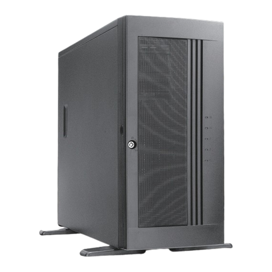
- Page 1 SR105 Plus Series Server Chassis User Manual January 2020 Version 2.3 A document provides an overview of product features, functions, architecture, and support specifications.
- Page 2 No license (express or implied, by estoppel or otherwise) to any intellectual property rights is granted by this document. Chenbro disclaims all express and implied warranties, including without limitation, the implied warranties of merchantability, fitness for a particular purpose, and non-infringement, as well as any warranty arising from course of performance, course of dealing, or usage in trade.
-
Page 3: Table Of Contents
SR105 Plus Series Table of Contents Table of Contents ............................3 List of Figures ..............................4 List of Tables ..............................5 Product Overview..........................6 1-1 Front Panel ..........................7 1-2 Back Panel ........................... 8 1-3 Security Features ......................... 9 1-4 Front Control Panel ........................10 1-5 Chassis Dimensions ........................ -
Page 4: List Of Figures
SR105 Plus Series List of Figures Figure 1 Front panel (enclosed) ........................ 7 Figure 2 Front panel (open) ........................7 Figure 3 Back panel with redundant PSU ....................8 Figure 4 Back panel with single PSU ......................8 Figure 5 Key lock and Kensington slot location .................. -
Page 5: List Of Tables
SR105 Plus Series List of Tables Table 1 Chenbro SR105 Plus specifications ....................6 Table 2 Front control panel ........................10 Table 3 System environmental specifications summary ................13 Table 4 System packing information ....................... 14 Table 5 Product weight information ....................... 14 Table 6 Drive power LED/activity LED behavior .................. -
Page 6: Product Overview
SR105 Plus Series 1. Product Overview The SR105 chassis has been modified to support both tool-less 3.5” HDD tray and PCIe 3.0 slot, and transformed into feature- advanced SR105 Plus. Beneath the chassis, an information sticker reads revision and manufacturing code, necessary for technical support. -
Page 7: Front Panel
SR105 Plus Series Front Panel Figure 1 Front panel (enclosed) A. 5.25” Storage Drive Bay C. USB Port Blank B. Front Control Panel Figure 2 Front panel (open) A. Bezel Door C. Front Control Panel B. 3.5” Storage Drive Bay... -
Page 8: Back Panel
SR105 Plus Series Back Panel Figure 3 Back panel with redundant PSU 1+1 Redundant PSU C. Rear Fan Rear I/O D. Expansion Slot Opening Figure 4 Back panel with single PSU PS/2 Single PSU C. Rear Fan Rear I/O D. Expansion Slot Opening... -
Page 9: Security Features
SR105 Plus Series Security Features Figure 5 Key lock and Kensington slot location Figure 6 Intrusion switch location A. Key Lock C. Kensington Slot B. Side Cover Lock D. Intrusion Switch │... -
Page 10: Front Control Panel
SR105 Plus Series Front Control Panel Figure 7 Front control panel Figure 8 Front control panel Table 2 Front control panel Label ICON Indicator, button or connector Power Button LAN1, LAN2 Activity LED Power LED HDD Activity LED Fan Alarm LED... -
Page 11: Chassis Dimensions
SR105 Plus Series Chassis Dimensions Figure 9 Chassis dimensions │... -
Page 12: Interior View
SR105 Plus Series Interior View Figure 10 Chassis components A. 3.5” HDD Cage C. Fan Assembly (HDD Cage) E. PCIe Fan (Option) B. Power Supply Unit D. 5.25” Storage Drive Bay F. System Board │... -
Page 13: System Level Environmental Specifications
SR105 Plus Series System Level Environmental Specifications The following table defines the system level specifications under operating and non-operating environments. Table 3 System environmental specifications summary Parameter Specification Temperature Operating 5º C to 35º C (41º F to 95º F) -
Page 14: System Packaging
System Packaging The original Chenbro packaging, where the server system is delivered, is designed to provide protection to a fully configured system and tested to meet ISTA (International Safe Transit Association) Test Procedure 1A. The packaging is also designed to be reused for shipment after system integration has been completed. -
Page 15: System Components Installation And Removal
SR105 Plus Series 2. System Components Installation and Removal SR105 Plus supports up to 4 x 3.5” hot-swap SAS/SATA HDD or 4 x 3.5” Internal SAS/SATA HDD. Support for different storage and peripheral options will vary depending on the system model and/or available accessory options installed. -
Page 16: Front Bezel Installation
SR105 Plus Series Front Bezel Installation Figure 12 Bezel installation 1. Lean the right side of the bezel on the front chassis. 2. Fully attach the bezel on the front of the chassis, and make sure the two internal latches are up. -
Page 17: 5.25" Device Installation
SR105 Plus Series 5.25” Device Installation Figure 14 5.25” device blank removal 1. Press two sides of the latch of the blank to release the blank as shown. 2. Pull the blank out. Figure 15 5.25” device side rail installation 1. -
Page 18: Figure 16 5.25" Device Installation
SR105 Plus Series Figure 16 5.25” device installation 1. Insert the 5.25” device into the drive bay. Note: Make sure both side rails are clipped on the latch. │... -
Page 19: Hdd Cage Installation
SR105 Plus Series HDD Cage Installation Figure 17 3.5” internal HDD cage installation 1. Insert the fan into the reserved slot. 2. Insert the HDD cage into the chassis. 3. Secure the thumb screws on the four sides of the HDD cage. -
Page 20: Figure 19 3.5" Hot-Swap Hdd Cage Fan Maintenance Step-1
SR105 Plus Series Figure 19 3.5” hot-swap HDD cage fan maintenance step-1 Figure 20 3.5” hot-swap HDD cage fan maintenance step-2 1. Unplug the power connector from the backplane. 2. Release the fan module latch and pull the fan module out of the fan cage. -
Page 21: Figure 21 3.5" Hot-Swap Hdd Tray Removal
SR105 Plus Series Figure 21 3.5” hot-swap HDD tray removal 1. Press the tray button to release the tray. 2. Pull the lever to remove the tray from the HDD cage. Figure 22 3.5” hot-swap HDD tray installation 1. Insert the HDD tray into the cage. -
Page 22: Figure 23 3.5" Hdd Installation (Tool-Less Type)
SR105 Plus Series Figure 23 3.5” HDD installation (tool-less type) 1. Engage two embossed pins with the side dimples on the HDD as shown. 2. Carefully push down the other side of the HDD until another two embossed pins and side dimples lock into place. -
Page 23: Figure 25 2.5" Hdd Installation (Screw Type)
1. Align the front of HDD/SSD with the anchor point on the tray . 2. Assemble 2.5” HDD/SSD into the tray by three screws from the bottom as shown. NOTE: Dedicated screw type is required for 2.5” HDD/SSD Installation, Chenbro P/N: 384-14602-3143A0. │... -
Page 24: Optional Fan (Add-In-Card Area) Installation
SR105 Plus Series Optional Fan (Add-In-Card Area) Installation Figure 26 Optional fan installation 1. Attach the fan with the tool-less fan holder as shown. 2. Insert the fan module into the reserved fan slot. NOTE: Please notice the arrow on the fan holder indicating the rear of the chassis. -
Page 25: Rear Fan Maintenance
SR105 Plus Series Rear Fan Maintenance Figure 28 Rear fan maintenance step-1 Figure 29 Rear fan maintenance step-2 1. Lift up the fan module latch at the bottom of the fan module without release. 2. Push the fan module down to remove it from the chassis. -
Page 26: Power Supply Installation
SR105 Plus Series Power Supply Installation Figure 30 Single PSU installation 1. Place the PSU inside the chassis, and ensure the alignment for four screw holes of PSU with the bracket of the chassis. 2. Secure the four screws as shown. -
Page 27: Backplane
SR105 Plus Series 3. Backplane Each drive tray includes separate LED indicators for drive activity and drive status. Light pipes integrated into the drive tray direct light emitted from the LEDs mounted next to each drive connector on the backplane to the drive tray faceplate, making them visible from the front of the system. -
Page 28: Storage Backplane Options
SR105 Plus Series Storage Backplane Options SR105 Plus supports the below backplanes: 1 x 3.5” 4-port 12Gbps Mini-SAS HD backplane 1 x 3.5” 4-port 12Gbps SAS/SATA backplane All available SAS/SATA backplanes include the following common features: 12Gbps SAS and 6Gbps SAS/SATA ... -
Page 29: 3.5" 4-Port 12Gbps Mini-Sas Hd Backplane
SR105 Plus Series 3.5” 4-Port 12Gbps Mini-SAS HD Backplane Table 7 Backplane specifications Specification Host Interface Mini-SAS HD (SFF-8643) HDD Interface SFF-8680 (SAS 29-pin) Hot-Swap Yes, allows users to replace devices online Display LED indicates storage device status Power LED – Off (Fault) –... -
Page 30: Figure 34 Backplane Rear View
SR105 Plus Series Figure 34 Backplane rear view Table 8 Connector and pin header function description Label Connector Description Drawing Mini-SAS HD For connecting to a mainboard or HBA, this Mini-SAS HD connector is applied. A proper cable selection is essential as well to make sure good signal integrity, which can be maintained for the whole connection path from a mainboard or HBA/RAID card to the HDD devices. - Page 31 SR105 Plus Series Label Connector Description Drawing The motherboard can monitor HDD temperature and fan status through this connector. However, the I2C connector on the motherboard side is dependent on vendors, so please contact our field application engineers to fully utilize this feature.
-
Page 32: 4-Port 12Gbps Sas/Sata Backplane
SR105 Plus Series 3.5” 4-Port 12Gbps SAS/SATA Backplane Table 9 Backplane specifications Specification Host Interface SATA 7-pin HDD Interface SFF-8680 (SAS 29-pin) Hot-Swap Yes, allows users to replace devices online LED indicates storage device status Display Power LED – Off (Fault) –... -
Page 33: Figure 35 Backplane Front View
SR105 Plus Series Figure 35 Backplane front view A. HDD_00 C. HDD_02 B. HDD_01 D. HDD_03 Figure 36 Backplane rear view │... -
Page 34: Table 10 Connector And Pin Header Function Description
SR105 Plus Series Table 10 Connector and pin header function description Label Connector Description Drawing SATA/SAS For connecting to a mainboard, this SATA/SAS 7-pin connector is applied. A proper cable selection is essential as well to make sure good signal integrity can be maintained for the whole connection path from mainboard HDD devices. -
Page 35: Maintenance And Service
(Dead on Arrival) If the products are found Defect On Arrival, please contact Chenbro’s regional sales or CQE and indicate the defective status via email along with product photos and description. You may need to return the defective item by request.
Need help?
Do you have a question about the SR105 Plus Series and is the answer not in the manual?
Questions and answers