Table of Contents
Advertisement
Quick Links
SPLIT-TYPE, HEAT PUMP AIR CONDITIONERS
TECHNICAL & SERVICE MANUAL
Indoor unit
[Model Name]
TPKFYP006BM142B
INDOOR UNIT
CONTENTS
PARTS CATALOG (OCBT516)
Model name
indication
No. OCHT516
R410A
Notes:
• This manual describes only
service data of the indoor
units.
1. SAFETY PRECAUTION .......................... 2
2. PARTS NAMES AND FUNCTIONS ........ 3
3. SPECIFICATION ................................... 10
4. OUTLINES AND DIMENSIONS ............ 13
5. WIRING DIAGRAM ............................... 14
6. REFRIGERANT SYSTEM DIAGRAM ........ 15
7. MICROPROCESSOR CONTROL ......... 16
8. TROUBLESHOOTING .......................... 22
9. DISASSEMBLY PROCEDURE ............. 29
April 2019
Advertisement
Table of Contents

Related Manuals for Mitsubishi Electric TRANE TPKFYP006BM142B


Summary of Contents for Mitsubishi Electric TRANE TPKFYP006BM142B
-
Page 1: Table Of Contents
SPLIT-TYPE, HEAT PUMP AIR CONDITIONERS April 2019 No. OCHT516 TECHNICAL & SERVICE MANUAL R410A Indoor unit [Model Name] Notes: TPKFYP006BM142B • This manual describes only service data of the indoor units. CONTENTS 1. SAFETY PRECAUTION ......2 2. PARTS NAMES AND FUNCTIONS ..3 3. -
Page 2: Safety Precaution
SAFETY PRECAUTION CAUTIONS RELATED TO NEW REFRIGERANT Cautions for units utilizing refrigerant R410A Use the following tools specifically designed for Do not use the existing refrigerant piping. use with R410A refrigerant. The old refrigerant and lubricant in the existing piping The following tools are necessary to use R410A refrigerant. -
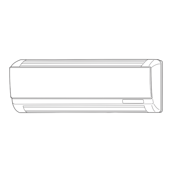
Page 3: Parts Names And Functions
PARTS NAMES AND FUNCTIONS 2-1. Indoor unit Air intake Filter Grille Vane Louver Air outlet 2-2. Wired Remote Controller <TAR-40MAA> <TAC-YT53CRAU> Wired remote controller function The functions which can be used are restricted according to each model. : Supported : Unsupported TAR-40MAA Function TAC-YT53CRAU... - Page 4 2-3. Wired Remote Controller <TAR-40MAA> Controller interface The functions of the function buttons change depending on the screen. Refer to the button function guide that appears at the bottom of the LCD for the functions they serve on a given screen. When the system is centrally controlled, the button function guide that corresponds to the locked button will not appear.
- Page 5 Display The main display can be displayed in two different modes: “Full” and “Basic”. The initial setting is “Full”. To switch to the “Basic” mode, change the setting on the Main display setting. (Refer to operation manual included with remote controller.) <Full mode>...
- Page 6 Main menu Press the button. MENU Move the cursor to the desired item with the buttons, and press the button. SELECT Operation Vane · Louver · Vent. (Lossnay) High power Comfort Manual vane angle 3D i-see Sensor Timer menu Timer ON/OFF timer Auto-OFF timer Weekly timer...
- Page 7 Continue from the previous page. Maintenance menu Error information Filter information Cleaning Auto descending panel Descending operation Descending adjustment Service menu Test run menu Test run Drain pump test run Maintenance information Model name input Serial No. input Dealer information input Initialize maintenance info.
- Page 8 Main menu list Main Setting and display items Setting details menu Operation Vane · Louver · Vent. Use to set the vane angle. (Lossnay) • Select a desired vane setting from 5 different settings. Use to turn ON/OFF the louver. •...
- Page 9 Main Setting and display items Setting details menu Initial Basic Main/Sub When connecting 2 remote controllers, one of them needs to be designated as setting setting a sub controller. Clock Use to set the current time. Daylight Set the daylight saving time. saving time Administrator The administrator password is required to make the settings for the following...
-
Page 10: Specification
SPECIFICATION 3-1. Specifications Service Ref. TPKFYP006BM142B Power source 1-phase 208/230V 60Hz Cooling capacity *1 kW (Nominal) *1 Btu/h 6,000 Power input 0.03 Current input 0.15 Heating capacity *2 kW (Nominal) *2 Btu/h 6,700 Power input 0.03 Current input 0.15 External finish Plastic, MUNSELL (1.0Y 9.2/0.2) External dimension 11-5/8 ×... - Page 11 3-2. Electrical parts specifications Service Ref. Symbol TPKFYP006BM142B Parts name Room temperature TH21 Resistance 30°F/15.8kΩ, 50°F/9.6kΩ, 70°F/6.0kΩ, 80°F/4.8kΩ, 90°F/3.9kΩ, 100°F/3.2kΩ detection thermistor Pipe temperature detection thermistor/ TH22 Resistance 30°F/15.8kΩ, 50°F/9.6kΩ, 70°F/6.0kΩ, 80°F/4.8kΩ, 90°F/3.9kΩ, 100°F/3.2kΩ liquid Pipe temperature detection thermistor/ TH23 Resistance 30°F/15.8kΩ, 50°F/9.6kΩ, 70°F/6.0kΩ, 80°F/4.8kΩ, 90°F/3.9kΩ, 100°F/3.2kΩ...
- Page 12 3-3. Sound levels Sound level at anechoic room: Low-Middle2-Middle1-High Wall Service Ref. Sound level dB (A) Unit 32-33-35-36 TPKFYP006BM142B 3.3 ft (1m) Measurement location * Measured in anechoic room. 3-4. NC curve TPKFYP006BM142B External static pressure: 0Pa Power source: 208,230V, 60Hz 70.0 High speed 65.0...
-
Page 13: Outlines And Dimensions
OUTLINES AND DIMENSIONS TPKFYP006BM142B Unit: inch (mm) 30-13/16(783) Emergency operation Emergency operation Receiver DEFROST/STAND BY lamp 32-3/32(815) Operation lamp 8-55/64(225) 25-3/16(640) 4-1/2(115) Air intake Air intake 4-3/16(106.7) (Direction) 1/8(3) installation plate Power supply Transmission Terminal block Air intake Address board (Direction) Air intake 25-3/16(640) -
Page 14: Wiring Diagram
WIRING DIAGRAM TPKFYP006BM142B OCHT516... -
Page 15: Refrigerant System Diagram
REFRIGERANT SYSTEM DIAGRAM TPKFYP006BM142B Refrigerant flow in cooling Refrigerant flow in heating Pipe temperature detection thermistor/gas TH23 Gas pipe Flare Strainer Pipe temperature detection (#100mesh) thermistor/liquid TH22 Liquid pipe Strainer Heat exchanger (#100mesh) Linear expansion valve Room temperature detection thermistor Strainer TH21 (#100mesh) -
Page 16: Microprocessor Control
MICROPROCESSOR CONTROL INDOOR UNIT CONTROL 7-1. COOL OPERATION <How to operate> 1 Press ON/OFF button. 2 Press [F1] button to display COOL. 3 Press [F2] [F3] button to set the set temperature. NOTE: The settable temperature range varies with the model of outdoor units and remote controller. RETURN SELECT MENU HOLD... - Page 17 7-2. DRY OPERATION <How to operate> 1 Press ON/OFF button. 2 Press [F1] button to display DRY. 3 Press [F2] [F3] button to set the set temperature. RETURN SELECT MENU HOLD <How to operate> 1 Press POWER ON/OFF button. 2 Press the operation MODE button to display DRY. 3 Press the TEMP.
- Page 18 7-3. FAN OPERATION <How to operate> 1 Press ON/OFF button. 2 Press [F1] button to display FAN. RETURN SELECT MENU HOLD <How to operate> 1 Press POWER ON/OFF button. 2 Press the operation MODE button to display FAN. Control Mode Control Details 1. Fan Set by remote controller.
- Page 19 7-4. HEAT OPERATION <How to operate> 1 Press ON/OFF button. 2 Press [F1] button to display HEAT. 3 Press [F2] [F3] button to set the set temperature. NOTE: The settable temperature range varies with the model of outdoor units and remote controller. RETURN SELECT MENU HOLD <How to operate>...
- Page 20 Control Mode Control Details Remarks 2-2. Residual heat exclusion mode • This control operates the same for the model When the condition changes the auxiliary heater ON to OFF (thermostat or operation without auxiliary heater. stop, etc.), the indoor fan operates in [Low] mode for 1 minute. 2-3.
- Page 21 7-5. AUTO OPERATION [AUTOMATIC COOL/HEAT CHANGE OVER OPERATION] <How to operate> 1 Press ON/OFF button. 2 Press [F1] button to display AUTO. 3 Press [F2] [F3] button to set the set temperature. NOTE: The settable temperature range varies with the model of outdoor units and remote controller. RETURN SELECT MENU HOLD...
-
Page 22: Troubleshooting
TROUBLESHOOTING 8-1. HOW TO CHECK THE PARTS TPKFYP006BM142B Parts name Checkpoints Room temperature Disconnect the connector then measure the resistance with a tester. detection thermistor (At the ambient temperature 50 to 86°F) (TH21) Pipe temperature Normal Abnormal detection thermistor/liquid Refer to “8-1-1. Thermistor”. 4.3 to 9.6k"... - Page 23 8-1-1. Thermistor < Thermistor for lower temperature > <Thermistor characteristic graph> Room temperature detection thermistor (TH21) Thermistor for Pipe temperature detection thermistor/liquid (TH22) lower temperature Pipe temperature detection thermistor/gas (TH23) Thermistor R =15kΩ ± 3% Fixed number of B=3480 ± 2% Rt=15exp { 3480( 273+(t-32)/1.8 30°F...
- Page 24 <Output pulse signal and the valve operation> The output pulse shifts in below order. Output Output Closing a valve : 1 → 2 → 3 → 4 → 1 (Phase) Opening a valve : 4 → 3 → 2 → 1 → 4 ø1 Note: ø2...
- Page 25 8-2. Function of DIP switch TPKFYP006BM142B The black square (■) indicates a switch position. Operation by switch Effective Switch Pole Function Remarks timing Thermistor Built-in remote <Room temperature Indoor unit Address board controller detection> position <Initial setting> Filter clogging Provided Not provided detection Filter cleaning sign...
- Page 26 Effective Switch Pole Function Remarks timing SW11 SW12 SW11 Address board 1s digit address How to set addresses <Initial setting> setting Example: If address is "3", remain SW12 SW12 SW11 SW12 (for over 10) at "0", and match SW11 (for 1 to 9) 10s digit Before address...
- Page 27 8-3. TEST POINT DIAGRAM 8-3-1. Indoor controller board TPKFYP006BM142B CN5V CN60 CN81 CN90 CN29 Vane motor output Linear expansion valve Connected to the Connected to the wireless Pipe temperature detection (MV) output (LEV) address board (CN82) remote controller board (W.B) thermistor/gas (TH23) 12 V DC pulse output 12 V DC pulse output...
- Page 28 8-3-2. Indoor power board TPKFYP006BM142B Power supply for indoor controller board Fan motor output (MF) Between 1 to 3 208/230 V AC CN2M Connected to the terminal block (TB5) FUSE (M-NET transmission connecting wire) 6A 250V 24–30 V DC (non-polar) CN35P Connected to the indoor controller board (CN35M) CN53P...
-
Page 29: Disassembly Procedure
DISASSEMBLY PROCEDURE TPKFYP006BM142B : Indicates the visible parts in the photos/figures. Be careful when removing heavy parts. OPERATION PROCEDURE PHOTOS/FIGURES 1. Removing the lower side of the indoor unit from the Figure 1 Figure 2 installation plate When there is removing plate (1) Remove the corner box at right lower side of the indoor unit and remove the removing plate from the corner box. - Page 30 OPERATION PROCEDURE PHOTOS/FIGURES 3. Removing the indoor controller board and indoor power Photo 2 board Electrical box (1) Remove the front panel. (Refer to procedure 2) cover (2) Remove the electrical box cover (screw 4 × 10). (See Photo 2) INDOOR CONTROLLER BOARD Screw for (1) Disconnect the following connectors on the indoor...
- Page 31 OPERATION PROCEDURE PHOTOS/FIGURES 6. Removing the electrical box Photo 6 Indoor controller board (1) Remove the front panel. (Refer to procedure 2) (2) Remove the electrical box cover. (See Photo 2) (3) Remove the water cut. (See Photo 3) Screw for Linear (4) Pull the nozzle assembly toward you as opening the catch ground wire...
- Page 32 OPERATION PROCEDURE PHOTOS/FIGURES 8. Removing the vane motor Photo 10 (1) Remove the front panel. (Refer to procedure 2) (2) Remove the screw of the electrical parts box cover, and remove the cover. Heat exchanger (3) Remove the 2 screws of the vane motor. Disconnect the relay connector and remove the motor Vane motor fixing from the shaft.
- Page 33 OCHT516...
- Page 34 MITSUBISHI ELECTRIC TRANE HVAC US LLC HEAD OFFICE: 1340 SATELLITE BOULEVARD, SUWANEE, GA 30024, USA CCopyright 2019 MITSUBISHI ELECTRIC CORPORATION Published: Apr. 2019 No.OCHT516 Made in Japan Specifications are subject to change without notice.
Need help?
Do you have a question about the TRANE TPKFYP006BM142B and is the answer not in the manual?
Questions and answers