Table of Contents
Advertisement
Quick Links
INSTALLATION MANUAL
MODEL
EUROPE
AUSTRALIA
SYSTEM
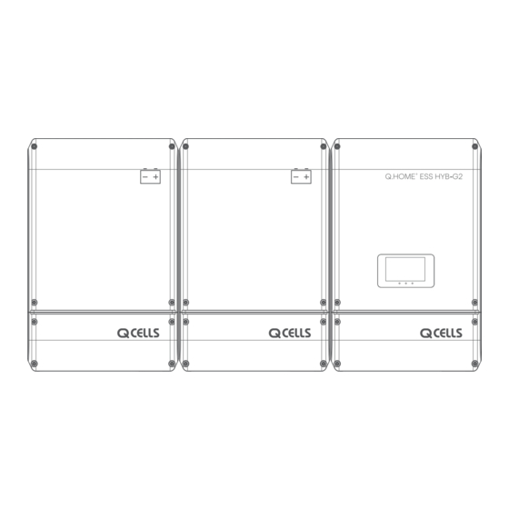
Q.HOME
ESS HYB-G2
+
INVERTER
Q.VOLT-G2 HYB-4.6kW.1.1
Q.VOLT-G2 HYB-5kW.1.1
Q.SAVE-G2 4kWh B1.1.1
BATTERY
Q.SAVE-G2 6.3kWh B1.1.1
NOTICE
• Do not operate with other components not approved by the ESS systems.
(Connecting other products in parallel to Q.HOME
ESS HYB-G2 may result in abnormal operation.)
+
• The internet connection is required to use all functions of the ESS system.
• If you have a problem, please contact the Q CELLS After Sales Service.
• The Specifications of the product may be modified without prior notice to improve product quality.
Advertisement
Table of Contents

Related Manuals for Q CELLS Q.VOLT-G2 HYB-4.6kW.1.1


Summary of Contents for Q CELLS Q.VOLT-G2 HYB-4.6kW.1.1
- Page 1 • The internet connection is required to use all functions of the ESS system. • If you have a problem, please contact the Q CELLS After Sales Service. • The Specifications of the product may be modified without prior notice to improve product quality.
-
Page 2: Table Of Contents
TABLE OF CONTENTS Table of Contents - - - - - - - - - - - - - - - - - - - - - - - - - - - - - - - - - - - - - - - - - - - - - - - - - - - - - - - - - - - - - - - - - - - - - - - - - - - Table of Tables - - - - - - -- - - - - - - - - - - - - - - - - - - - - - - - - - - - - - - - - - - - - - - - - - - - - - - - - - - - - - - - - - - - - - - - - - - - - - - Table of Figures... - Page 3 A Connection Method of the DC Line from the PV - - - - - - - - - - - - - - - - - - - - - - - - - - - - - - - - - - - - Circuit Breaker -- - - - - - - - - - - - - - - - - - - - - - - - - - - - - - - - - - - - - - - - - - - - - - - - - - - - - - - - - - - - - - - - - - - - 5.5.1...
- Page 4 8.5.3 Load Information Display - - - - - - - - - - - - - - - - - - - - - - - - - - - - - - - - - - - - - - - - - - - - - - - - - - - - - - - - - - - - - 8.5.4 Battery Information Display - - - - - - - - - - - - - - - - - - - - - - - - - - - - - - - - - - - - - - - - - - - - - - - - - - - - - - - - - - - -...
-
Page 5: Table Of Tables
TABLE OF TABLES [ Table 1-1 : Symbol Description 1 ] - - - - - - - - - - - - - - - - - - - - - - - - - - - - - - - - - - - - - - - - - - - - - - - - - - - - - - - - - - - - - - - [ Table 1-2 : Symbol Description 2 ] - - - - - - - - - - - - - - - - - - - - - - - - - - - - - - - - - - - - - - - - - - - - - - - - - - - - - - - - - - - - - - - [ Table 1-3 : Symbol Description (Battery) ]... - Page 6 TABLE OF FIGURES [ Figure 2-1 : MEN Link (Only for Australia) ] - - - - - - - - - - - - - - - - - - - - - - - - - - - - - - - - - - - - - - - - - - - - - - - - - - - - - - [ Figure 2-2 : TN-S Network System Connection Diagram (Single-Phase) ] - - - - - - - - - - - - - - - - - - - - - - - - - - [ Figure 2-3 : TT Network System Connection Diagram (Single-Phase) ]...
- Page 7 [ Figure 5-22 : Front Cover Assembly Process 1 ] - - - - - - - - - - - - - - - - - - - - - - - - - - - - - - - - - - - - - - - - - - - - - - - - - [ Figure 5-23 : Front Cover Assembly Process 2 ] - - - - - - - - - - - - - - - - - - - - - - - - - - - - - - - - - - - - - - - - - - - - - - - - - [ Figure 6-1 : Internet Connection ]...
-
Page 8: Information In This Manual
1. Information in this Manual 1.1 About this Manual This is the installation manual for the Q.HOME ESS HYB-G2. Please read this installation and user manual carefully before installing and operating the Q.HOME ESS HYB-G2. It contains important safety instructions. The warranty will be void if you fail to follow the instructions in this manual. - Page 9 Symbols Description Beware dangerous voltage. The ESS operates at high voltage. All works related to the ESS can only be performed by an electrical technician. Beware of hot surface. The INVERTER can become hot during operation. Avoid contact during operation. Follow the guidelines in all relevant documents enclosed along with the INVERTER.
- Page 10 Symbols Description Symbols Description Out position of a bi-stable Bidirectional terminal rating push control Caution : Risk of Electric Shock and Energy Storage Timed Input terminal or rating Discharge Caution : Risk of Hearing Damage and Wear Hearing Protection Output terminal or rating Wear hearing protection [ Table 1-2 : Symbol Description 2 ] Symbols...
-
Page 11: Safety
Any substitute use of this device, random change in any of its parts, and use of components other than sold or recommended by Q CELLS will nullify the product’s guarantee. For example, Q CELLS Li-Ion Battery energy storage should not be replaced by other manufacturer’s Battery storages. -
Page 12: Network System Connection Diagram
2.1.2 Network System Connection Diagram 2.1.2.1 Single Phase TN-S Network System(Single-Phase) GRID Battery Battery Pack #1 Pack #2 TOUCH (Utility Meter) DISPLAY Earth Bar PV#1 GRID PV#2 RS-485 Circuit Breaker (CAN) (CAN) (CAN) LOAD Energy Meter (ESS Meter) (RS-485) PV1 Array PV2 Array Circuit Circuit Breaker... - Page 13 2.1.2.2 Three Phase TN-S Network System(Three-Phase) GRID Battery Battery Pack #1 Pack #2 (Utility Meter) TOUCH L1 L2 L3 N DISPLAY Earth Bar Circuit PV#1 GRID Breaker PV#2 RS-485 (CAN) (CAN) (CAN) LOAD Energy Meter (ESS Meter) (RS-485) Circuit L1 L2 L3 N Breaker Three-Phase Loads...
-
Page 14: Safety Precautions
2.2 Safety Precautions CAUTION High voltages in power conditioning circuits. Lethal hazard of electric shock or serious burns. All work on the PV modules, INVERTER, converters, and Battery systems must be carried out by qualified personnel only. Wear rubber gloves and protective clothing (protective glasses and boots) when working on high voltage/high current systems such as INVERTER and Battery systems. -
Page 15: Product Overview
2.3 Product Overview The Q.HOME ESS HYB-G2 includes the PV INVERTER, Battery charger/discharger, Li-Ion Battery, and EMS. The basic operating modes consist of Stand-Alone (Back-up) mode, PV generation mode, PV generation + charge/discharge mode. The operation mode of this product is automatically determined by the EMS algorithm. -
Page 16: Battery Product Overview
2.3.2 Battery Product Overview Q.SAVE-G2 4kWh Q.SAVE-G2 6.3kWh [ Figure 2-7 : Part View of Battery Pack ] Description Battery (Made by Samsung SDI) BMS Board (Made by Samsung SDI) Terminal and Circuit Breaker Cable Gland for power cables BMS Communication Connector Bracket Connected Part [ Table 2-2 : Part Description of Battery Pack ] Safety... -
Page 17: Basic Specifications (Europe)
2.3.3 Basic Specifications (Europe) PV Generator Data (DC) Max. input total power 6.6 kWp Max. input power per string 3.3 kWp Max. input voltage 550 V Min. input voltage / Initial input voltage 125 V / 150 V per string MPPT voltage range 125 V - 500 V Max. -
Page 18: Basic Specifications (Australia & New Zealand)
2.3.4 Basic Specifications (Australia & New Zealand) PV Generator Data (DC) Max. input total power 6.6 kWp Max. input power per string 3.3 kWp Max. input voltage 550 V Min. input voltage / Initial input voltage 125 V / 150 V per string MPPT voltage range 125 V - 500 V Max. -
Page 19: Grounding The Pv Inverter
The PV INVERTER complies with the local requirements for grounding the PV INVERTER. Q CELLS recommends connecting and grounding the PV INVERTER’s frame and other electricity conducting surfaces in such a way that there is continuous conduction in order to achieve maximum protection for systems and persons. -
Page 20: Package Removal And Inspection
3. Package Removal and Inspection CAUTION Included in this box are a Battery and printed circuit board. Therefore, special care must be taken in handling. Make sure to have at least two persons deliver and remove the package. 3.1 Package Removal 3.1.1 Removing the INVERTER Enclosure Package As shown in the [Figure 3-1], remove the package components from the enclosure in the following order. -
Page 21: Removing The Battery Enclosure Package
3.1.2 Removing the Battery Enclosure Package As shown in the [Figure 3-2], remove the package components from the enclosure in the following order. 1. Place the system on the installation location. 2. Turn the box upside down. 3. Open the box. 4. -
Page 22: Checking Components On The Packing List
3.1.3 Checking Components on the Packing List Once the product has been delivered, refer to the [Figure 3-3], [Figure 3-4], [Figure 3-5], [Table 3-1], [Table 3-2], and [Table 3-3] check the entire components included in the package and the correct number of the quantity listed in the table. - Page 23 Battery Packing List BATTERY INSTALLATION MANUAL [ Figure 3-4 : Packing List of Battery Pack ] Part Name Code No. Quantity Battery ASSY 0147000123CA Upper Wall Bracket 6447300054AD Lower Wall Bracket 6447300055AD Bridge Bracket 74190024AAAD Wall Mounting Screw 67613074AAAD Down Bracket Screw 67613075AAAD Bridge Screw 67613078AAAD...
-
Page 24: Checking For Damage In Delivery
ESS HYB-G2 in it, check for any possible damage caused in transit and ensure the correct number of the components therein. If there is a scratch on the enclosure, contact the Q CELLS after sales service for inspection and service. 3.3 Identifying Q.HOME ESS HYB-G2 Attached on the enclosure of this product is the Type Label where the identity of this product is described. - Page 25 Seoul Korea 04541 Seoul Korea 04541 Product Name : Q.HOME ESS HYB-G2 Product Name : Q.HOME ESS HYB-G2 Hybrid Inverter : Q.VOLT-G2 HYB-5kW.1.1 Hybrid Inverter : Q.VOLT-G2 HYB-4.6kW.1.1 Max. Voltage 550 V Max. Voltage 550 V Rated Input Voltage 400 V...
-
Page 26: Installation
4. Installation 4.1 Selection of Installation Location CAUTION Danger to life due to fire or explosion! Danger to life due to high voltages! Despite careful construction, a fire can occur with electrical devices. Do not install the Q.HOME ESS HYB-G2 on the following locations: On flammable construction materials;... -
Page 27: Dimensions
4.1.1 Dimensions Once the Q.HOME ESS HYB-G2 has been assembled, its dimension is 467.6 x 721.6 x 212.5 mm. The [Figure 4-1] show the outer dimensions of the device after assembly, respectively. 467.6 mm 212.5 mm 467.6 mm 212.5 mm [ Figure 4-1 : Dimension of Q.HOME ESS HYB-G2 ] 4.1.2 Ambient Conditions and Temperatures... -
Page 28: Position (Location Selection)
300 mm 600 mm [ Figure 4-2 : Minimum Clearance for Q.HOME ESS HYB-G2 ] 4.1.4 Position (Location Selection) When choosing the place of installation, observe the following conditions: • Install on a wall or strong structure capable of bearing the weight of the equipment. •... -
Page 29: Mounting Instructions
4.2 Mounting Instructions CAUTION There is risk of injury if the ESS is lifted incorrectly or dropped while being transported or when attaching it to or removing it from the wall mounting bracket. Transport and lift the ESS carefully. It is important to ensure the drilling locations are not located on any electrical wiring within the wall. - Page 30 STEP 3 • Step 3 : Secure the upper bracket. U P P E R B R A C K E T U P P E R B R A C K E T [ Figure 4-5 : Bracket on the Wall in Step 3 ] STEP 4 •...
- Page 31 STEP 5 • Step 5 : Lift the INVERTER and secure it to the upper bracket. - Step 5-1 : Hang the INVERTER to upper bracket. - Step 5-2 : Secure the lower bracket. STEP 5-1 STEP 5-2 [ Figure 4-7 : Bracket on the Wall in Step 5 ] STEP 6 •...
-
Page 32: Floor Mount - Mounting Instructions
4.3 Floor Mount - Mounting Instructions NOTICE • The Floor Mount must use the frame provided by the manufacturer, All four directions should be fastened with bolts to the bottom. Mount Plate Stand Column D-Bracket L-Bracket Screw M8x16 Screw M6x8 Nut M8 (1ea) (2ea) -
Page 33: Electrical Connections
STEP 6 STEP 7 • Step 6 : After assembling INVERTER A’SSY and • Step 7 : Assemble the battery in the same way. Floor Mount Option, tighten SCREW. * Use the Wall Mount Screw to disassemble it. M8x45, Washer (2 point) [ Figure 4-10 : Floor Mount assembly Step 1-7 ] 5. -
Page 34: The Overview Of Electrical Connection
5.1 The Overview of Electrical Connection 5.1.1 Electrical System Connection The Q.HOME ESS HYB-G2 has two solar energy inputs (PV1, PV2). 3.3kW (per string) is the maximum output for each PV input. The AC output of Q.HOME ESS HYB-G2 is connected to the Home Load and the Grid. -
Page 35: Cable Gland Specification
5.1.3 Cable Gland Specification External cable diameter 10 mm - 17 mm Grid, Load, Battery Cable Gland (M25) IP66 External cable diameter 4.5 mm - 9 mm Communication Cable Gland (M16) IP66 [ Table 5-2 : Cable Gland Specification ] 5.1.4 Overall Drawing of the Q.HOME ESS HYB-G2 5.1.4.1 Overall Drawing of the INVERTER... - Page 36 5.1.4.2 Overall Drawing of the Battery The [Figure 5-4] and [Figure 5-5] shows the overall drawing of the Battery pack. Please refer to the figure of the drawing for installation and maintenance. [ Figure 5-4 : Battery Bottom View ] [ Figure 5-5 : Battery Front inside View ] Part List Cable Gland...
-
Page 37: Opening The Front Case Cover
Do not remove the top cover except for special events(A / S). For normal installation it is not necessary and not allowed to open the upper cover. Only Q CELLS After Sales is allowed to open or to instruct installer to open in case of necessary service. -
Page 38: Battery Connections
5.3 Battery Connections CAUTION • Make sure the AC circuit breaker, PV switch and DC circuit breaker of the Battery are disconnected before starting electrical cable connections. • Battery replacement can only be carried out by qualified personnel. If the Battery needs to be changed, it should be placed with a product which meets the manufacturer’s specifications. - Page 39 2. Check inner circuit breaker and terminal in Battery case. [ Figure 5-7 : Inside of Q.HOME ESS HYB-G2 ] 3. Connect the (+) and (-) wire (PCS) to the marked terminal (Battery). And then connect the ground terminal.(See Chapter 5.6.1) [ Figure 5-8 : Battery Pack and INVERTER Connection ] 4.
- Page 40 5. As shown in the [Figure 5-10], connect Battery communication connector is composed of BMS Communication Adaptor and connect from outside. If you use more than one Battery (8kwh or more), use the adaptor (Amphenol) for Battery communication. (EX. If you use 3 Battery, you need 2 adaptor for BMS communication.) When using the adaptor, hold the communication cable and fasten the silver color of the adaptor to anticlockwise.
-
Page 41: A Connection Method Of The Dc Line From The Pv
5.4 A Connecting Method of the DC Line from the PV Refer to the [Figure 5-1] for the PV module connection. The lead wires, coming from the PV modules, are directly connected to the HYB-G2. For the connection to the distribution box, connect each to the terminals of the solar energy of PV1+, PV1-, PV2+, and PV2-. - Page 42 Check the cable connection of PV strings for the correct polarity and that the open circuit voltage does not exceed the INVERTER input limit 550 V. If open circuit voltage is higher than 550 V, status of INVERTER is fault. The Male product is connected to the lead wire coming from the distribution box in the PV side, and the Female part is attached to the Q.HOME ESS HYB-G2.
-
Page 43: Circuit Breaker
5.5 Circuit Breaker 5.5.1 AC Circuit Breaker and DC Disconnect Switch The circuit breaker populated on the distribution board varies depending on the installer. Follow the installation standards to install a circuit breaker satisfying the voltage, the current specification of the Grid, PV and the Battery. Refer to Chapter 5.1.2 for cable specification. Standard Short circuit current rating AC circuit breaker... -
Page 44: Connection Method Between Grid And Load
5.6 Connection Method between Grid and Load CAUTION Any failure of the INVERTER when it is not connected to ground through the appropriate terminal is not covered by the warranty. 5.6.1 Feature and Size of Cable The following lists the insulation strip length details for each conductor cross section. Refer to Chapter 5.1.2 for cable specification. -
Page 45: Grid Connection Method
5.6.2 Grid Connection Method To connect the Grid of the INVERTER, you need 3 connections : Ground, Neutral and Phase. In any case, connection of the INVERTER to ground is mandatory. Insert the Grid cable into the INVERTER through the AC cable gland. Strip 9 mm of cable from the cable to connect to the Grid. -
Page 46: Battery Connection Method
5.6.4 Battery Connection Method To connect the Battery, you need 3 connections : Ground, (+) and (-). In any case, connection of the INVERTER to ground is mandatory. To connect the Battery, insert the cable into the INVERTER through the Battery cable gland. Strip 9 mm of cable from the cable to connect to Load. -
Page 47: A Connecting Method Of Drm Connection (Only For Australia)
5.7 A Connecting Method of DRM connection (Only for Australia) The INVERTER supports the DRM (Demand Response Mode) function as specified in AS/NZS 4777.2:2020. The terminal block inside the INVERTER is used for connecting to a demand response enabling device (DRED). The DRED asserts DRMs. -
Page 48: An Installation Method Of Energy Meter Electrical Connection
5.8 An Installation Method of Energy Meter Electrical Connection The electrical installation method of the digital energy meter (energy meter) must comply with installation method provided by the digital energy meter manufacturer. However, the digital energy meter must be selected. The [Figure 5-15] shows the electrical cable connection and the communication lines of the digital energy meter. -
Page 49: Closing The Front Case Cover
5.9 Closing the Front Case Cover NOTICE Make sure that connection between connector and ground match correctly, before reassembling front lower cover. 1. Close the bottom cover of INVERTER and Battery case. [ Figure 5-21 : Outside of INVERTER and Battery Case ] 2. - Page 50 3. As shown in the [Figure 5-23], Use a hexagon wrench (size: M4) to fasten the bolt clockwise. Please do not close the cover here Screwing because it will still be necessary Torque = 1.4 Nm to access the bottom part later during installation.
-
Page 51: Communication Connection
6. Communication Connection 6.1 Internet Connection 6.1.1 Components • Wired Router (not provided in the product package) • RJ45 general LAN Cable (not provided in the product package, the length of the cable must be less than 10 m.) 6.1.2 Connection Block Diagram •... -
Page 52: The Communication Terminal
6.2 The Communication Terminal • Energy meter : Connect to RS-485 Energy Meter, Out Connector Board CN2. • Short bar is connected to CN1. Refer to Chapter 7.3. Energy Meter RS485/CAN I/O EXT Emergency [ Figure 6-4 : Communication Terminal ] Short bar location Description Pin map... -
Page 53: Energy Meter Connection
6.3 Energy Meter Connection 6.3.1 RS-485 Interface 6.3.1.1 Components • RS-485 Meter - The Energy Meter uses RS-485 Interface for communication. • Connection line (Not provided in the product package) - It should be applied to a twisted-pair type. • Cable length limit - The RS-485 meter communication cable must be used within 100 m. -
Page 54: Recommended Energy Meter List
[ Figure 6-7 : Energy Meter Connection Method ] 6.4 Recommended Energy Meter List Company Model Interface Direction CARLO GAVAZZI EM24-DIN.AV9.3.X.IS.X RS-485 Bi-direction CARLO GAVAZZI EM112-DIN.AV0.X.S1.X RS-485 Bi-direction Q CELLS Q.HOME Manager RS-485 Bi-direction [ Table 6-3 : Recommended Meter List ] Communication Connection... -
Page 55: Entering Initial Installation Information
7. Entering Initial Installation Information You can use the following procedure to enter the initial installation information and to monitor the operational information of this system appropriately on server. 7.1 Preparations for installer • A laptop or a smart phone is required. 7.2 Overview of initial information input stages •... -
Page 56: Sim (System Install Manager) Connection
[ Figure 7-1 : Setting Laptop IP ] CAUTION • Turn off Wifi. • Only turn on Local Area Connection. 7.3.3 SIM (System Install Manager) connection 7.3.3.1 Direct connection 1. Confirm that power is off. 2. Connect two short bars to pin 1-2 and 7-8 on Out Connector Board as shown in the [Figure 7-2]. It makes Control Board to have static IP address so that you can access to System Install Manager (SIM) Page. - Page 57 3. Connect a LAN cable to laptop and ESS. 4. Turn on AC circuit breaker at grid side, turn PV switch to ON position. 5. On the laptop, open an internet browser, enter http://17.91.23.196:8000 in address bar to access SIM page. If you do not know the password, please contact your supplier. Refer to Chapter 13 for contact information.
-
Page 58: Sim(System Install Manager) Battery Installing
7.3.4 SIM(System Install Manager) Battery Installing 7.3.4.1 Main Page Select and Save a country and a grid regulation. 7.3.4.2 Battery Install - Initialize Step 1 ) Click here. Step 2 ) Select Initial ID function and click SELECT button. Entering Initial Installation Information... - Page 59 Step 3 ) Connect the Communication Cable of all the Batteries you want to install. Step 4 ) Then click the START button. Step 5 ) If it completes normally, the same screen appears. If there is a problem return to “Step 1”. Then click the FINISH button to complete Initialize.
- Page 60 7.3.4.3 Battery installation process. Step 1 ) Click here. Step 2 ) Select Auto function and click SELECT button. Step 3 ) Select the number of batteries you want to install. Step 4 ) Click the ENTER button. Entering Initial Installation Information...
- Page 61 Step 5 ) Connect the Communication Cable of the first Battery you want to install. Step 6 ) Then click the ‘Configure ID !!!’ button. Step 7 ) Wait until the battery connected the communication Cable is installed. Entering Initial Installation Information...
- Page 62 Step 8 ) When the installation is completed for the desired Number of batteries, ‘SAVE BMS ID’ button will Appear as below. Then click the ‘SAVE BMS ID’ button to complete The installation. Step 9 ) If there are still batteries left to install, the following Screen appears. Repeat the previous step. Entering Initial Installation Information...
-
Page 63: Battery Installation Process With Hmi
7.3.5 Battery Installation Process with HMI Please check the LCD screen on top cover of PCS. Follow the instruction below for battery communication. Step 1 ) Touch Battery Icon 10 times. Step 2 ) Select. [Initial ID] Step 3 ) Click Next Button. - Page 64 Step 8 ) • Disconnect all communication cable. Open Circuit Breakers. Step 9 ) Select [Auto] and set the amount of the battery to install. • Example) Amount of batteries to install : 2 Step 10 ) Click Next Button. Step 11 ) •...
-
Page 65: Installation Settings
7.3.6 Installation Settings 7.3.6.1 Country / Grid Regulation Settings • Select a country and the grid regulation. Note For compliance to AS/NZS 4777.2:2020, please select from region A/B/C. Please contact your local grid operator for which region is required. 7.3.6.2 Product Setting •... - Page 66 7.3.6.5 Advanced Settings • Adjust grid protection setpoints (Configurable grid protection setpoints depend on the selected grid regulation.) • [AU] 10 Min Voltage If the average system voltage for 10 minutes exceeds the detection level, the inverter is blocked from the system within 3 seconds.
- Page 67 • [AU] Active Power Voltage The inverter changes the maximum input·output active power depending on system voltage. The inverter responds in two ways depending on charging or discharging operation. • During charging operation: If frequency decreases below V , it decreases input active power, and it W2_CH does not exceed the designated active power input constraint W1 below V...
- Page 68 • [AU] Reactive Power Q(U) A volt-var response mode changes reactive power absorbed or supplied by an inverter depending on system voltage. The response curve needed for the volt-var response is operated according to the four default values of volt response and the corresponding reactive power standard. Supplying −10 −20...
- Page 69 Parameter Default Values Range Export Hard Limit Level [%] 0 to 100 Export Hard Limit Time [s] 0 to 100 Export Soft Limit Level [%] 0 to 100 Export Soft Limit Time [s] 0 to 100 Generation Hard Limit Level [%] 0 to 100 Generation Hard Limit Time [s] 0 to 100...
- Page 70 7.3.6.6 Save and Restart • Save onto the system after all the procedures above are completed. Entering Initial Installation Information...
-
Page 71: Checking The Settings Information
7.3.7 Checking the settings information 7.3.7.1 Firmware version • Select a maintenance menu • Check the firmware version and country 7.3.7.2 Region / Grid regulation • Select a installation settings menu • Check the country and grid regulation Entering Initial Installation Information... -
Page 72: Web
7.4 Web Page Connection 7.4.1 Web Page Connection Open an Internet browser of your laptop or smart phone, then enter the designated address. Then the system information input page pops up. • Input URL: www.qcells-qonnect.com • Concurrent support of PC and Mobile 1. - Page 73 3. Check your warranty provider and click yours. [ Figure 7-5 : Select warranty ] 4. Select your country. [ Figure 7-6 : Select country ] Entering Initial Installation Information...
-
Page 74: Product Registration
7.4.2 Product Registration Detailed manual for product registration and advanced settings is provided as a separate file. The manual download procedure is as follows. NOTICE • To install the product, you must obtain an installer membership instead of a general membership. - Page 75 6. After login, click “User Manual” Button. [ Figure 7-8 : Main page - User Manual ] 7. In the pop-up window of the user manual, find the registration manual, i.e., Server Register Quick Guide, and click the file download button [ Figure 7-9 : Main page - User Manual Download ] Entering Initial Installation Information...
-
Page 76: Operating Test
8. Operating Test 8.1 LED Indications As shown in the [Figure 8-1], the LED of Q.HOME ESS HYB-G2 is located at bottom of LCD. The color of LED depend on current status of INVERTER and LED display information can be checked in [Table 8-1]. -
Page 77: Home Screen Configuration Information
8.2.2 Home Screen Configuration Information Hybrid ESS 02 : 52 PM LOAD 5.06 kW 1.47 kW BATTERY GRID 1.60 kW 1.98 kW Normal [ Figure 8-4 : Standby State Indication Screen before the EMS Command ] Screen Information Description Time Information Display time information Operation Status Internal communication connection status... - Page 78 8.2.2.1 Home menu structure If you touch next or previous button, the screen is displayed as shown in the [Figure 8-5]. The description of each screen refer to Chapter 8.5 [ Figure 8-5 : Home Menu Structure ] Operating Test...
-
Page 79: Turning Off The System
8.3 Turning off the System CAUTION When turning off the system, make sure to turn off the battery circuit breaker. it is very important to prevent battery deep discharge. 1. Turn PV Switch on INVERTER unit to OFF position. 2. Make sure that ESS has stopped. 3. -
Page 80: Information Display
8.5 Information Display 8.5.1 PV Information display [ Figure 8-6 : PV Information Display ] Display Description PV1 Voltage Display current PV1 voltage PV1 Current Display current PV1 current PV1 Power Display current PV1 power PV2 Voltage Display current PV2 voltage PV2 Current Display current PV2 current PV2 Power... -
Page 81: Grid Information Display
8.5.2 Grid Information display [ Figure 8-7 : Grid Information Display ] Display Description Voltage Display Grid voltage Frequency Display Grid frequency Current Display Grid current Power Display Grid active power Power Factor Display Grid power factor Today Feed-in Power Display today’s power received from the Grid Today Feed-out Power Display today’s electricity sent to the Grid... -
Page 82: Load Information Display
8.5.3 Load Information display [ Figure 8-8 : Load Information Display ] Display Description Voltage Display Load voltage Current Display Load current Frequency Display Load frequency Power Display Load active power Today Power Display today’s Load power Total in Power Display the amount of power used in today's Load Graph Display Load power graph (Daily/Weekly/Monthly/Yearly) -
Page 83: Battery Information Display
8.5.4 Battery Information display [ Figure 8-9 : Battery Information Display ] Display Description Voltage Display Battery voltage Current Display Battery current Power Display Battery charging / discharging power State of charge State of health Today Charge Power Display today's Battery charge power Today Discharge Power Display Battery power factor Total Power Charge... -
Page 84: System Information Display
8.5.5 System Information display [ Figure 8-10 : System Information Display ] Display Description Product Model Name of this product Product Country Country using this product IP Address IP Address Software Version Software version of this product PMS Version Software version of PMS PCS Master Version Software version of PCS master PCS Slave Version... -
Page 85: Error Information Display
8.5.6 Error Information display [ Figure 8-11 : Error Information Display ] Display Description Date The date the fault occurred. Time The time the fault occurred. Error Type of fault (See Chapter 9.1) If there are more than 10 errors, the first error is cleared. [ Table 8-9 : Error Information Display Description ] Operating Test... -
Page 86: Problem Confirmation
9. Problem Confirmation Checking event codes is available on the website (www.q-cells.com). If the Internet is not available, the event codes cannot be checked. 9.1 General Events The general events contain warnings and protection. The warning level events does not stop the generating process. A displayed warning message automatically disappears as soon as the issue is resolved. - Page 87 WEB Display HMI Display Description Measures D05P BDC1 DOC P BDC1 Discharge The product stops the generating process RMS Over Current because a significant protection event has Protection occurred. Wait until the event message disappears. After the event message is removed, it automatically returns to normal.
- Page 88 WEB Display HMI Display Description Measures D21P BDC UV P BDC RMS Under The product stops the generating process Voltage Protection because a significant protection event has occurred. Wait until the event message disappears. After the event message is removed, it automatically returns to normal. If it is not removed until the time limit is reached, it is converted to a significant event.
- Page 89 WEB Display HMI Display Description Measures G01P INV I TZM P INV Current Trip Zone The product stops the generating process Master Protection because a significant protection event has occurred. Wait until the event message disappears. After the event message is removed, it automatically returns to normal.
- Page 90 WEB Display HMI Display Description Measures G07P INV UT P INV Module Temp When the switch temperature is low. Under Temp Protection Wait until the event message disappears. After the event message is removed, it automatically returns to normal. If it is not removed until the time limit is reached, it is converted to a significant event.
- Page 91 WEB Display HMI Display Description Measures G21P DC Injection P DC Injection Protection The product stops the generating process because a significant protection event has occurred. Wait until the event message disappears. After the event message is removed, it automatically returns to normal. If it is not removed until the time limit is reached, it is converted to a significant event.
- Page 92 WEB Display HMI Display Description Measures G34P Relay L3 P Relay L3 Abnormal Relay L3 is burned out. Operation Protection A / S is required. G35P Relay L4 P Relay L4 Abnormal Relay L4 is burned out. Operation Protection A / S is required. L01P Load OC P Load RMS Over...
- Page 93 WEB Display HMI Display Description Measures L06P Load OF P Load Over Frequency The product stops the generating process Protection because a significant protection event has occurred. Wait until the event message disappears. After the event message is removed, it automatically returns to normal. If it is not removed until the time limit is reached, it is converted to a significant event.
- Page 94 WEB Display HMI Display Description Measures S06P PV1 OC P PV1 RMS Over The product stops the generating process Current Protection because a significant protection event has occurred. Wait until the event message disappears. After the event message is removed, it automatically returns to normal. If it is not removed until the time limit is reached, it is converted to a significant event.
- Page 95 WEB Display HMI Display Description Measures S16P PV2 OC P PV2 RMS Over The product stops the generating process Current Protection because a significant protection event has occurred. Wait until the event message disappears. After the event message is removed, it automatically returns to normal. If it is not removed until the time limit is reached, it is converted to a significant event.
- Page 96 WEB Display HMI Display Description Measures S31P DCLINK V DCLINK Voltage Trip The product stops the generating process TZM P Zone Master Protection because a significant protection event has occurred. Wait until the event message disappears. After the event message is removed, it automatically returns to normal.
-
Page 97: Battery General Events (Protection)
9.1.2 Battery General Events (Protection) Type : PROTECTION WEB Display HMI Display Description Measures B01P BAT1 CHG BAT1 Charge Over The product stops the generating process OC P Current Protection because a significant protection event has occurred. Wait until the event message disappears. - Page 98 WEB Display HMI Display Description Measures B07P BAT1 COM P BAT1 Communication Power reset of the system is required. Protection If the symptom persists after reset, replace the cable connecting the Battery pack and the INVERTER. After replacement, repair of BMS or PCS Control Board is necessary.
- Page 99 WEB Display HMI Display Description Measures B15P BAT2 CEL UV BAT2 Cell or Rack When the minimum cell or rack voltage is Under Voltage below protection level, thus terminating the Protection system. Automatically returns to normal when the minimum cell or rack voltage goes above the limit value.
- Page 100 WEB Display HMI Display Description Measures B23P BAT3 CEL V BAT3 Cell Voltage Power reset of the system is required. HOLD P Sensing Data Hold If the symptom still occurs after reset, repair Protection of BMS or PCS Control Board is necessary. B24P BAT3 CEL OV BAT3 Cell or Rack...
- Page 101 WEB Display HMI Display Description Measures B31P BAT4 CHG OC BAT4 Charge Over The product stops the generating process Current Protection because a significant protection event has occurred. Wait until the event message disappears. After the event message is removed, it automatically returns to normal. If it is not removed until the time limit is reached, it is converted to a significant event.
- Page 102 WEB Display HMI Display Description Measures B37P BAT4 COM P BAT4 Communication Power reset of the system is required. If the Protection symptom persists after reset, replace the cable connecting the Battery pack and the INVERTER. After replacement, repair of BMS or PCS Control Board is necessary.
- Page 103 WEB Display HMI Display Description Measures B45P BAT5 CEL UV BAT5 Cell or Rack When the minimum cell or rack voltage is Under Voltage below protection level, thus terminating the Protection system. Automatically returns to normal when the minimum cell or rack voltage goes above the limit value.
-
Page 104: System General Events (Protection)
HMI Display Description Measures P01P Unknown Unregistered Failure It is an unregistered fault. Turn off and restart the system. Please contact the Q CELLS Service –Hotline, if an error occurs continuously. P03P DSP-EMG DSP-Emergency Trip Please check emergency switch. TRIP P... -
Page 105: Maintenance
10. Maintenance 10.1 Cleaning the Cover NOTICE Qualified Person Only! Damage to the ESS due to the use of cleaning agents. If the ESS is dirty, clean the enclosure, the enclosure lid, the type label and the LEDs using only clean water and a cloth. -
Page 106: Battery Maintenance
10.3 Battery Maintenance CAUTION All work or service on the ESS and electrical connections must be supervised by personnel knowledgeable about batteries and the required precautions. When replacing Battery packs, replace old ones with the same type and number of batteries (Check the type label or serial numbers/model numbers on Battery packs). -
Page 107: The List Of Replaceable Parts
The Li-Ion Battery module can be replaced if it fails to work properly. The Q.HOME ESS HYB-G2 uses a Battery module manufactured by SAMSUNG SDI. When you have to replace the Battery module, please contact Q CELLS and provide the item's name and the serial number of the Q.HOME ESS HYB-G2. 10.4.2 PV Connector The PV connector can be replaced when it is damaged. -
Page 108: Technical Specifications
11. Technical Specifications Europe PV Data (DC) Max. input total power 6.6 kWp Max. input power per string 3.3 kWp Max. input voltage 550 V Min. input voltage / Initial input voltage 125 V / 150 V per string MPPT voltage range 125 V - 500 V Max. - Page 109 Grid Input Rated / Maximum input apparent power 3000 / 4000 VA Rated / Maximum input active power 3000 / 4600 W Rated input voltage 230 Va.c. Rated / Maximum continuous input current 13/25 Aa.c. Rated input frequency 50 Hz Max.
- Page 110 Australia & New Zealand PV Data (DC) Max. input total power 6.6 kWp Max. input power per string 3.3 kWp Max. input voltage 550 V Min. input voltage / Initial input voltage 125 V / 150 V per string MPPT voltage range 125 V - 500 V Max.
- Page 111 Grid Input Rated / Maximum input apparent power 3000 / 4000 VA Rated / Maximum input active power 3000 / 4600 W Rated input voltage 230 Va.c. Rated / Maximum continuous input current 13/25 Aa.c. Rated input frequency 50 Hz Max.
- Page 112 Australia & New Zealand Europe Ambient temperature (°C) [ Figure 11-1 : Derating Curve ] Item Cell body / module temperature Specification T < 0 °C 0 °C ≤ T < 10 °C 3.5 A Q.SAVE-G2 10 °C ≤ T < 25 °C 4 kWh 25 °C ≤...
- Page 113 Item Cell body / module temperature Specification T < -20 °C -20 °C ≤ T < -10 °C Q.SAVE-G2 -10 °C ≤ T < 0 °C 10.5 A 4 kWh 0 °C ≤ T < 40 °C 19.6 A 40 °C ≤ T < 50 °C 10.5 A Maximum 50 °C ≤...
-
Page 114: Disassembly
12. Disassembly 12.1 Disassembly CAUTION Risk of injury due to the heavy weight of the Q.HOME ESS HYB-G2! Make sure to have at least two persons move this system. CAUTION Lethal hazards may be caused by high voltages in the Q.HOME ESS HYB-G2! CAUTION Lethal hazards may be caused by voltage spikes if the positive and negative terminal of... -
Page 115: Packaging
If the Battery or the product life has expired, the regulations for the disposal of electronic products in that region must be followed, and if it is not possible, send them to Q CELLS. The address is indicated in the contact information (See Chapter 13). -
Page 116: Contact
• For technical problems or inquiries for use, please contact the installation company. To receive customer support, the following information is required. 1. Product type : Q.VOLT-G2 HYB-4.6kW.1.1 (Europe), Q.VOLT-G2 HYB-5.0kW.1.1 (Australia) 2. Serial Number : 3. PV module type and configuration 4. - Page 118 Manufacturer & Warranty Provider: Hanwha Solutions Corporation 86 Cheonggyecheon-ro, Jung-gu, Seoul Korea 04541...
Need help?
Do you have a question about the Q.VOLT-G2 HYB-4.6kW.1.1 and is the answer not in the manual?
Questions and answers