Advertisement
Quick Links
NOTE:
Please read all instructions
carefully before using this
product
Table of Contents
Safety Notice
Hardware Identifier
Assembly Instruction
Parts List
Warranty
Ordering Parts
Model
IVT-50
Retain This
Manual for
Reference
05-27-09
OWNER'S
MANUAL
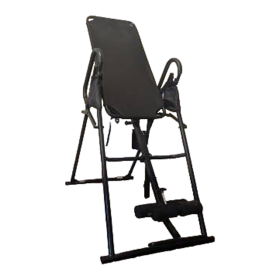
MARCY
INVERSION TABLE
14777 DON JULIAN RD., CITY OF INDUSTRY, CA 91746
Tel: (800) 999-8899 Fax: (626) 961-9966
www.impex-fitness.com
info@impex-fitness.com
®
CLASSIC
IVT-450
®
IMPEX
INC.
Advertisement

Related Manuals for Impex MARCY IVT-450


Summary of Contents for Impex MARCY IVT-450
- Page 1 INVERSION TABLE Assembly Instruction IVT-450 Parts List Warranty Ordering Parts Model IVT-50 Retain This Manual for Reference 05-27-09 OWNER'S MANUAL ® IMPEX INC. 14777 DON JULIAN RD., CITY OF INDUSTRY, CA 91746 Tel: (800) 999-8899 Fax: (626) 961-9966 www.impex-fitness.com info@impex-fitness.com...
-
Page 2: Table Of Contents
ORDERING PARTS..................… BEFORE YOU BEGIN Thank you for selecting the MARCY CLASSIC IVT-450 Inversion Table by ® IMPEX INC. For your safety and benefit, read this manual carefully before using the machine. As a manufacturer, we are committed to provide you complete customer satisfaction. -
Page 3: Important Safety Notices
BEFORE BEGINNING ANY EXERCISE PROGRAM, CONSULT YOUR PHYSICIAN. THIS IS ESPECIALLY IMPORTANT FOR INDIVIDUALS OVER THE AGE OF 35 OR PERSONS WITH PRE-EXISTING HEALTH PROBLEMS. READ ALL INSTRUCTIONS BEFORE USING ANY FITNESS EQUIPMENT. IMPEX INC. ASSUMES RESPONSIBILITY PERSONAL INJURY PROPERTY DAMAGE SUSTAINED BY OR THROUGH THE USE OF THIS PRODUCT. - Page 4 WARNING LABEL REPLACEMENT The Warning Label shown here has been placed on the Rear Support Frame. If the label is missing or illegible, please call customer service at 1-800-999-8899 for replacement. Apply the label in location shown.
-
Page 5: Hardware Identifier
HARDWARE IDENTIFIER NOTE: The following parts are not drawn to scale. Please use your own ruler to measure the size. -
Page 6: Assembly Instructions
ASSEMBLY INSTRUCTION Tools Required for Assembling the Machine: Two Adjustable Wrenches and Allen Wrenches. NOTE: It is strongly recommended that two or more people assemble this machine to avoid possible injury. STEP 1 (See Diagram 1) A.) Do not tighten the Nuts and Bolts until instructed to do so. B.) Attach Front Support Frame (#1) to Rear Support Frame (#2). - Page 7 DIAGRAM 1...
- Page 8 STEP 2 (See Diagram 2) A.) Attach the two Pivot Brackets (#12) to the Backrest Frame (#7) from each side. B.) Secure each Pivot Bracket to the Backrest Frame with two M8 x ¾” Allen Bolts (#38) and two Ø ¾” Washers (#45). C.) Lift the Backrest Frame and insert the two Pivot Brackets into the open slot on Rear Support Frame (#2).
- Page 9 STEP 3 (See Diagram 3) A.) Attach the Left Handle (#8) to Front Support Frame (#1). Secure it with one M8 x ¾” Allen Bolt (#35), one Ø 5/8” Washer (#46), and one M8 Aircraft Nut (#43). B.) Attach the Left Handle to the Rear Support Frame (#2). Secure it with one M8 x 1 ¾” Allen Bolt (#36), one Ø...
- Page 10 STEP 4 (See Diagram 4) A.) Pull up the Foot Adjustment Lock Pin (#23). Insert the Foot Lock Frame (#13) into the Adjustment Fame (#11). Push down the Pin to securely lock the Foot Lock Frame in position. B.) Insert the Foot Support (#6) into the bottom of Adjustment Frame. Secure it with one M8 x 1 5/8”...
- Page 11 STEP 5 (See Diagram 5) A.) Pull out the Backrest Adjustment Lock Pin (#22). Insert the Adjustment Frame (#11) into the opening on the vertical frame on the back of Backrest Frame (#7). Push back the Pin into the selected hole on Adjustment Frame.
-
Page 12: Exploded Diagram
EXPLODED DIAGRAM... -
Page 13: Parts List
PARTS LIST KEY NO. DESCRIPTION QUANTITY Front Support Frame Rear Support Frame Short Horizontal Support Right Long Horizontal Support Left Long Horizontal Support Foot Support Backrest Frame Left Handle Right Handle Foam Tube Adjustment Frame Pivot Bracket Foot Lock Frame U-shaped Lock Pin Inversion Adjustment Belt Curved Foam Roll... -
Page 14: Warranty
IMPEX authorized service center or for products used for commercial or rental purposes. No other warranty beyond that specifically set forth above is authorized by IMPEX.
Need help?
Do you have a question about the MARCY IVT-450 and is the answer not in the manual?
Questions and answers