
Related Manuals for Mitsubishi Electric FR-700PJ


Summary of Contents for Mitsubishi Electric FR-700PJ
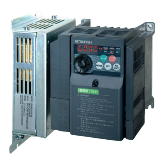
- Page 1 INVERTER Model FR-F 700PJ GREAT ENERGY SAVING WITH THE COMPACT BODY Premium high-efficiency IPM motor MM-EFS compatible series...
- Page 2 The Easy and Compact Inverter Inverter Control for Energy Saving FR-F700PJ for (1) Energy saving with speed control (2) Energy saving with Optimum • Features excitation control (General-purpose motors) The consumed power of a variable-torque load, such as fans, pumps, Energy Saving and blowers, is proportional to the cube of its rotation speed.
- Page 3 Wire and Space Saving Optimum for Fan and Pump Applications (1) A lineup of Filterpack models available (1) Enhanced PID control (3) Automatic restart after instantaneous power failure function / ying start function •The power factor improving DC reactor, common mode choke (line •A Filterpack allows flexible installation and various layouts in the •To save energy in low-speed operation: PID output shutoff (sleep) function noise filter), and capacitive filter (radio noise filter) are all essential for air...
- Page 4 Application Example Line Up Great energy saving e ect obtained in medium air ow Inverter F R - F 7 4 0 P J - 3.7K (When the electricity cost is 14 yen/kWh, and the CO emission is [1,000 kWh 0.555 ton - CO emission] ) Water-cooling pump for a showcase Air conditioning in a Mitsubishi plant...
- Page 5 Connection Example AC power supply Use within the permissible power supply specifications of the inverter. To ensure safety, use a moulded case circuit breaker, Enclosure surface operation RS-232C - RS-485 converter is earth leakage circuit breaker or magnetic panel (FR-PA07) required when connecting to PC contactor to switch power ON/OFF.
- Page 6 Standard Specifications Rating Three-phase 200V power supply Inverter Model FR-F720PJ-K 0.75 Applicable general-purpose motor capacity 0.75 (kW) 12.1 17.1 22.1 Rated capacity (kVA) Rated current (A) 10.0 16.5 23.8 31.8 120% 60s, 150% 0.5s (inverse-time characteristics) Overload current rating ...
- Page 7 Common Specification High carrier frequency PWM control (V/F control)/Optimum excitation control/General-purpose magnetic flux vector Control method control/IPM motor control Output frequency range 0.2 to 400Hz 0.06Hz/60Hz (terminals 2 and 4: 0 to 10V/10-bit) Analog input Frequency setting 0.12Hz/60Hz (terminals 2 and 4: 0 to 5V/9-bit) resolution 0.06Hz/60Hz (terminal 4: 0 to 20mA/10-bit) Digital input...
- Page 8 Overcurrent during acceleration, overcurrent during constant speed, overcurrent during deceleration, overvoltage during acceleration, overvoltage during constant speed, overvoltage during deceleration, inverter protection thermal operation, motor protection thermal operation, heatsink overheat, undervoltage , input phase loss , output side Protective earth (ground) fault overcurrent at start , output phase loss, external thermal relay operation , PTC thermistor function Protective/warning operation , parameter error, PU disconnection, retry count excess , CPU fault, brake transistor alarm, inrush...
- Page 9 Outline Dimension Drawings Without a Filterpack FR-F720PJ-1.5K to 3.7K FR-F720PJ-0.4K, 0.75K FR-F740PJ-0.4K to 3.7K 2-φ5 hole ∗ φ5 hole Rating Rating plate plate FR-F740PJ-0.4K and 0.75K are not provided with the cooling fan. Inverter Model Inverter Model FR-F720PJ-0.4K 112.5 FR-F720PJ-0.75K 132.5 FR-F720PJ-1.5K, 2.2K...
- Page 10 With a Filterpack A Filterpack can be installed on the side or rear panel of the inverter. This is a sample outline dimension drawing. The shape differs by the model. Filterpack installed on the rear panel Inverter Model FR-F720PJ-0.4KF 172.5 FR-F720PJ-0.75KF 192.5 FR-F720PJ-1.5KF, 2.2KF...
- Page 11 Filterpack FR-BFP2-0.4K, 0.75K, 1.5K, 2.2K, 3.7K FR-BFP2-5.5K, 7.5K, 11K, 15K FR-BFP2-H0.4K, H0.75K, H1.5K, H2.2K, H3.7K FR-BFP2-H5.5K, H7.5K, H11K, H15K 2-φ4.5 hole 2-φ4.5 hole 2-φC hole 2-φC hole Rating Rating plate plate 12.5 12.5 (25) L-bracket for rear panel installation of the inverter ...
- Page 12 Terminal Connection Diagram Sink logic Main circuit terminal Control circuit terminal With Filterpack ∗1 Remove the jumper Filterpack Inverter across the terminals FR-BFP2 ∗2 DC reactor (FR-HEL) P1 and P/+ to install When connecting a DC reactor, remove the Filterpack. ∗1 jumper across P1 and P/+.
- Page 13 Terminal Specification Explanation Terminal Type Terminal Name Terminal Specification Symbol Connect to the commercial power supply. R/L1, S/L2, Do not connect anything to these terminals when using the high power factor converter (FR- AC power input T/L3 HC2) or power regeneration common converter (FR-CV). To use Filterpack, connect the R, S, and T cables of Filterpack.
- Page 14 Terminal Type Terminal Name Terminal Specification Symbol 1 changeover contact output indicates that the inverter protective function has activated and the output stopped. Relay output A, B, C Fault: discontinuity across B-C (continuity across A-C), (fault output) Normal: continuity across B-C (discontinuity across A-C) Contact capacity:230VAC 0.3A (power factor =0.4) 30VDC 0.3A Switched Low when the inverter output frequency is equal to or higher than the starting frequency (initial value 0.5Hz).
- Page 15 Explanation of the Operation Panel The operation panel cannot be removed from the inverter. (g) Operation status indicator (a) Unit indicator (h) Parameter setting mode indicator (b) Monitor (4-digit LED) (i) Monitor indicator (c) Setting dial (j) Operation mode indicator (d) Start command (e) MODE key (k) STOP/RESET key...
- Page 16 Basic Operation of the Operation Panel Operation mode switchover At power-ON (External operation mode) PU Jog operation mode (Example) Value change and frequency flicker alternately. PU operation mode Frequency setting has been (output frequency monitor) written and completed!! (After 1s) General-purpose Set frequency Keep pressing...
- Page 17 Explanations of Parameter unit Parameter unit (FR-PU07) The parameter unit is a convenient tool for inverter setting Description such as direct input method with a numeric keypad, Use for parameter setting operation status indication, and help function. Press to choose the parameter setting mode. First priority monitor is displayed.
- Page 18 FR Configurator (INVERTER SETUP SOFTWARE) FR-SW3-SETUP-WE ® ® (Windows 2000 Professional SP4 or later, Windows XP Home Edition SP2 or later, ® ® ® Windows XP Professional SP2 or later, Windows Vista SP1 or later, Windows 7 supported) FR Configurator is software that offers an easy operating environment. Can be utilized effectively from inverter setting up to maintenance.
- Page 19 Parameter List For simple variable-speed operation of the inverter, the initial setting of the parameters may be used as they are. Set the necessary parameters to meet the load and operational specifications. Parameter setting, change and check can be made from the operation panel.
- Page 20 Refer Initial Parameter Name Unit Range Application Number Value page Setting "1" returns all parameters except Pr.CL Parameter clear 0, 1 calibration parameters to the initial values. Setting "1" returns all parameters to the initial ALLC All parameter clear 0, 1 values.
-
Page 21: Table Of Contents
Extended mode parameter REMARKS The parameters marked with indicate simple mode parameters. The shaded parameters in the table allow its setting to be changed during operation even if "0" (initial value) is set in Pr.77 Parameter write selection. Minimum Refer Func-... - Page 22 Minimum Refer Func- Initial Customer Parameter Name Setting Range Setting tion Value Setting Increments Page Up-to-frequency sensitivity 0 to 100% 0.1% Output frequency detection 0 to 400Hz 0.01Hz Output frequency detection for reverse 0 to 400Hz, 9999 0.01Hz 9999 rotation Second acceleration/deceleration time 0 to 3600s 0.1s...
- Page 23 Minimum Refer Func- Initial Customer Parameter Name Setting Range Setting tion Value Setting Increments Page PID control automatic switchover 0 to 400Hz, 9999 0.01Hz 9999 frequency PID action selection 0, 20, 21 PID proportional band 0.1 to 1000%, 9999 0.1% 100% PID integral time 0.1 to 3600s, 9999...
- Page 24 Minimum Refer Func- Initial Customer Parameter Name Setting Range Setting tion Value Setting Increments Page 0, 1, 3, 4, 7, 8, 11 to 16, 25, 26, 46 to 48, 57, 64, 70, 79, 90 to 93, 95, 96, 98 to 101, 103, 104, RUN terminal function selection 107, 108, 111 to 116, 125, 126, 146 to 148,...
- Page 25 Minimum Refer Func- Initial Customer Parameter Name Setting Range Setting tion Value Setting Increments Page Communication operation command 0, 1 source Communication speed command 0 to 2 source Communication startup mode selection 0, 1, 10 Communication EEPROM write 0, 1 selection Communication error count —...
- Page 26 Minimum Refer Func- Initial Customer Parameter Name Setting Range Setting tion Value Setting Increments Page Speed control P gain 1 0 to 1000% Speed control integral time 1 0 to 20s 0.001s 0.333s — Speed detection hysteresis 0 to 5Hz 0.01Hz Input phase loss protection selection 0, 1...
- Page 27 Minimum Refer Func- Initial Customer Parameter Name Setting Range Setting tion Value Setting Increments Page PID display bias coefficient 0 to 500, 9999 0.01 9999 (934) PID display bias analog value 0 to 300% 0.1% (934) PID display gain coefficient 0 to 500, 9999 0.01 9999...
- Page 28 Explanations of Parameters In the following section, the following marks indicate the operable controls: ..V/F control (General-purpose motor), ..General-purpose magnetic flux vector control (General-purpose motor), MFVC MFVC MFVC ..IPM motor control (dedicated IPM motor). (Parameters without any marks are valid for all controls.) Also the following marks indicate parameter types: ....Simple mode parameters, ....
- Page 29 When the motor has a built-in PTC thermistor, the output can be input to the terminal 2 and terminal 10. When the input from the PTC 7, 8, 20, 44, 45, 791, 792 thermistor reaches the resistance setting in Pr.561 PTC thermistor Acceleration/deceleration time setting protection level, the PTC thermal error signal (E.PTC) is output and the inverter trips.
- Page 30 15, 16 Minimum motor rotation frequency Jog operation Pr.15 Jog frequency Pr.16 Jog acceleration/deceleration time You can set the frequency and acceleration/decelertion time for Pr.13 Starting frequency jog operation. Jog operation can be performed from either the Set the frequency where the motor starts running. outside or PU.
- Page 31 22, 23, 48, 66, 154, 156, 157 Stall prevention operation Acceleration/deceleration pattern Pr.29 Acceleration/deceleration pattern selection Pr.22 Stall prevention operation level Pr.23 Stall prevention operation level compensation factor at double speed You can set the acceleration/deceleration pattern suitable for MFVC MFVC MFVC application.
-
Page 32: Frequency
31 to 36, 552 41 to 43, 870 Avoid mechanical resonance points Detection of output frequency (frequency jump) (SU, FU signal) Pr.31 Frequency jump 1A Pr.32 Frequency jump 1B Pr.41 Up-to-frequency sensitivity Pr.42 Output frequency detection Pr.43 Output frequency detection for reverse rotation Pr.33 Frequency jump 2A Pr.34 Frequency jump 2B Pr.870 Speed detection hysteresis... - Page 33 The cumulative power monitor value digit can be shifted to the right 52, 54, 170, 171, 268, 563, 564, 891 by the number set in Pr. 891. By setting “0” in Pr. 170, the cumulative power monitor can be DU/PU monitor change, cumulative cleared.
- Page 34 When = "1 (initial value) or 11", automatic restart operation is Pr. 162 30, 57, 58, 162, 165, 299, 611 performed in a reduced voltage system, where the voltage is gradually risen with the output frequency unchanged from prior to an Automatic restart after instantaneous instantaneous power failure independently of the coasting speed of power failure/flying start under General-...
- Page 35 57, 162, 611 Automatic restart after instantaneous Remote setting function power failure/flying start under IPM Pr.59 Remote function selection motor control Even if the operation panel is located away from the enclosure, you can use contact signals to perform continuous variable-speed Pr.57 Restart coasting time operation, without using analog signals.
- Page 36 65, 67 to 69 71, 450 Retry function at alarm occurrence Use the constant torque motor (applied motor) Pr.65 Retry selection Pr.67 Number of retries at fault occurrence Pr.68 Retry waiting time Pr.69 Retry count display erase Pr.71 Applied motor If an alarm occurs, the inverter resets itself automatically to restart.
- Page 37 72, 240, 260 73, 267 Carrier frequency and Soft-PWM Analog input selection selection Pr.73 Analog input selection Pr.267 Terminal 4 input selection Pr.72 PWM frequency selection Pr.240 Soft-PWM operation selection You can select the function that switches between forward rotation Pr.260 PWM frequency automatic switchover and reverse rotation according to the analog input terminal You can change the motor sound.
- Page 38 Reset selection, disconnected PU Operation mode selection detection Pr.79 Operation mode selection Pr.340 Communication startup mode selection Used to select the operation mode of the inverter. Pr.75 Reset selection/disconnected PU detection/PU stop selection Mode can be changed as desired among operation using external You can select the reset input acceptance, disconnected PU (FR- command signals (External operation), operation from the operation PU04/FR-PU07) connector detection function and PU stop...
- Page 39 Specify operation mode at power on (Pr.340) When power is switched on or when power comes back on after 80, 71 instantaneous power failure, the inverter can be started up in the General-purpose magnetic flux vector Network operation mode. control After the inverter has started up in the Network operation mode, MFVC...
- Page 40 82 to 84, 90, 96, 298 117 to 124, 342, 343, 502, 549, 779 Initial communication setting Offline auto tuning MFVC MFVC MFVC Pr.117 PU communication station number Pr.118 PU communication speed Pr.82 Motor excitation current Pr.83 Rated motor voltage Pr.119 PU communication stop bit length Pr.120 PU communication parity check Pr.84 Rated motor frequency...
- Page 41 (2) Communication EEPROM write selection (Pr.342) 125, 126, 241, C2(902) to C7(905), C22(922) to C25(923) When parameter write is performed from PU connector Analog input frequency change and connected to the inverter, parameter’s storage device can be changed from EEPROM + RAM to only RAM. When adjustment (calibration) performing parameter change frequently, set "1"...
- Page 42 127 to 134, 553, 554, 575 to 577, C42(934) to C45(935) 150 to 153, 166, 167 PID control Detection of output current (Y12 signal) detection of zero current (Y13 signal) Pr.127 PID control automatic switchover frequency Pr.128 PID action selection Pr.129 PID proportional band Pr.150 Output current detection level Pr.130 PID integral time...
- Page 43 178 to 182 161, 295 Function assignment of input terminal Operation selection of the operation Pr.178 STF terminal function selection Pr.179 STR terminal function selection panel Pr.180 AU terminal function selection Pr.181 RM terminal function selection Pr.182 RH terminal function selection Pr.161 Frequency setting/key lock operation selection Use these parameters to select/change the input terminal Pr.295 Magnitude of frequency change setting...
- Page 44 190, 192 Terminal assignment of output terminal Increase cooling fan life Pr.190 RUN terminal function selection Pr.192 A,B,C terminal function selection Pr.244 Cooling fan operation selection You can change the functions of the open collector output terminal You can control the operation of the cooling fan (1.5K or higher) and relay output terminal.
- Page 45 251, 872 Selection of motor stopping method Input/output phase failure protection and start signal selection Pr.250 Stop selection Pr.251 Output phase loss protection selection Pr.872 Input phase loss protection selection Used to select the stopping method (deceleration to a stop or You can disable the output phase failure protection function that coasting) when the start signal turns off.
- Page 46 296, 297 Operation at instantaneous power Password function failure Pr.296 Password lock level Pr.297 Password lock/unlock MFVC MFVC MFVC Registering a 4-digit password can restrict parameter reading/ Pr.261 Power failure stop selection writing. When a power failure or undervoltage occurs, the inverter can be ...
- Page 47 338, 339, 551 495, 496 Operation command source and speed Remote output function (REM signal) command source during Pr.495 Remote output selection Pr.496 Remote output data 1 communication operation You can utilize the ON/OFF of the inverter's output signals instead of the remote output terminal of the programmable controller.
- Page 48 555 to 557 665, 882, 883, 885, 886 Current average value monitor signal Regeneration avoidance function Pr.665 Regeneration avoidance frequency gain Pr.555 Current average time Pr.556 Data output mask time Pr.882 Regeneration avoidance operation selection Pr.557 Current average value monitor signal output reference current Pr.883 Regeneration avoidance operation level The average value of the output current during constant speed Pr.885 Regeneration avoidance compensation frequency limit value...
- Page 49 Refer to the section about Pr.41 Pulse train output of output power Refer to the section about Pr.251 (Y79 signal) 882, 883, Refer to the section about Pr.665 Pr.799 Pulse increment setting for output power 885, 886 After power ON or inverter reset, output signal (Y79 signal) is output in pulses every time accumulated output power, which is counted after the Pr.799 Pulse increment setting for output power is 888, 889...
- Page 50 Energy 892 to 899 Saving Description and Formula Increments Energy saving monitor Monitor Item Pr.892 Load factor Power Pr.893 Energy saving monitor reference (motor capacity) Power saving is added up per hour. saving 0.01kWh Pr.894 Control selection during commercial power-supply operation ...
- Page 51 999, AUTO PU contrast adjustment Automatic parameter setting Pr.991 PU contrast adjustment Pr.999 Automatic parameter setting AUTO Automatic parameter setting Contrast adjustment of the LCD of the parameter unit (FR-PU04/ Parameter settings are changed as a batch. Those include communication parameter settings for the Mitsubishi human FR-PU07) can be performed.
- Page 52 Protective Functions When an alarm occurs in the inverter, the protective function is activated bringing the inverter to an alarm stop and the PU display automatically changes to any of the following error (alarm) indications. Function Name Description Indication Operation panel lock Appears when operation is tried during operation panel lock.
- Page 53 Function Name Description Indication External thermal relay Appears when the external thermal relay connected to the terminal OH operated. operation PTC thermistor Appears when the resistance of the PTC thermistor, which is connected across terminals 2 and 10, reaches operation the Pr.561 PTC thermistor protection level setting or higher.
- Page 54 Options and peripheral devices List of options Applicable Name Model Applications, Specifications, etc. Inverter FR-PU07 Parameter unit Applicable for all Interactive parameter unit with LCD display (Eight languages) FR-PU04 models Enclosure surface operation Applicable for all This operation panel enables inverter operation and monitoring of FR-PA07 panel frequency, etc.
- Page 55 Stand-alone option Name (model) Specification and Structure An operation panel that enables inverter operation and monitoring of frequency setting, etc. from the enclosure surface. Specification Item Description Surrounding air -10°C to +50°C (non-freezing) Enclosure surface temperature Ambient humidity 90%RH or less (non-condensing) operation panel Storage...
- Page 56 Name (model) Specification and Structure Improves the power factor and reduces the harmonic current at the input side. Connect a DC reactor in the DC section of the inverter. Selection method Select a DC reactor according to the applied motor capacity. (When a general-purpose motor is used, select it according to the motor capacity even if the capacity is smaller than the inverter capacity.) ...
- Page 57 Name (model) Specification and Structure Install an EMC filter (ferrite core) to reduce the electromagnetic noise generated from the inverter. Effective in the range from about 0.5MHz to 5MHz. Outline dimension MCCB Inverter FR-BSF01 FR-BLF Power R/L1 Spply S/L2 T/L3 2-φ5...
- Page 58 Name (model) Specification and Structure Provides a braking capability greater than that is provided by an external brake resistor. This option can also be connected to the inverters without built-in brake transistors. Three types of discharging resistors are available. Make a selection according to the required braking torque. ...
- Page 59 Name (model) Specification and Structure Connection diagram Resistor unit or Inverter discharging resistor NCCB Resistor unit or Motor R/L1 discharging resistor Three-phase S/L2 AC power supply T/L3 Brake unit FR-BU2-(H) Reset Brake permission signal Signal for Resistor unit master/slave ...
- Page 60 Name (model) Specification and Structure Enables continuous regenerative operation at 100% torque. This option can support continuous regenerative operations including line operation. This converter eliminates the need of preparing brake units per inverter. This converter can cut down the total space and the cost. ...
- Page 61 Name (model) Specification and Structure Substantially suppresses power harmonics to realize the equivalent The power regeneration function comes standard. capacity conversion coefficient K5 = 0 in "the Harmonic Suppression The common converter driving with several inverters is possible. Guidelines for Consumers Who Receive High Voltage or Special High Voltage"...
- Page 62 Name (model) Specification and Structure Limits surge voltage applied to motor terminals when driving a 400V class motor with an inverter (available only with general-purpose motors). Supports FR-F740PJ-5.5K to 37K. Specification Connection diagram Model FR-BMF-HK Applicable motor within 100m capacity (kW) ...
- Page 63 Moulded Case Circuit Breaker (MCCB), Earth Leakage Circuit Breaker (ELB), Input Side Magnetic Contactor, Cable size Moulded Case Circuit Breaker (MCCB) Input Side Magnetic Recommended cable Earth Leakage Circuit Breaker (ELB) gauge Contactor Motor (NF or NV type) Applicable Output Power factor improving...
- Page 64 Selection of rated sensitivity current of earth leakage circuit breaker When using the earth leakage current breaker with the Example inverter circuit, select its rated sensitivity current as follows, 5.5mm 5.5mm independently of the PWM carrier frequency: Noise filter Breaker designed for harmonic and surge suppression 3φ...
- Page 65 Precautions for Operation/Selection Precautions for use of the inverter Safety Precautions To operate the inverter correctly and safely, be sure to read the "instruction manual" before starting operation. This product has not been designed or manufactured for use with any equipment or system operated under life-threatening conditions. ...
- Page 66 Installation Wiring While power is ON or for some time after power-OFF, do not touch Applying the commercial power supply to input terminals (U, V, W) of an IPM motor will burn the IPM motor. The IPM motor must be the motor since the motor will be extremely hot.
- Page 67 Precautions for selection Connection with machine Direct connection Inverter capacity selection When installing, align the motor shaft center and the machine shaft. Insert a liner underneath the motor or the machine legs as required When operating a special motor or more than one motor in parallel to make a perfect alignment.
- Page 68 Precautions for Peripheral Device Selection Installation and selection of molded Secondary side measuring instrument case circuit breaker When the wiring length between the inverter and motor is long, select the device that has enough current rating. Install a molded case circuit breaker (MCCB) on the power receiving Otherwise the measuring instrument or CT which is used especially for side to protect the wiring of the inverter primary side.
- Page 69 Earth (Ground) Leakage currents When the inverter is run in the low acoustic noise mode, more leakage Capacitances exist between the inverter I/O cables, other cables and currents occur than in the non-low acoustic noise mode due to high- earth and in the motor, through which a leakage current flows. Since its speed switching operation.
- Page 70 Harmonic suppression guideline For compliance to "Harmonic suppression guideline of the general- purpose inverter (input current of 20A or less) for consumers other than Harmonic currents flow from the inverter to a power receiving point via specific consumers" published by JEMA a power transformer.
- Page 71 Application to Motor Application to standard motor Motor loss and temperature rise Vibration The motor operated by the inverter has a limit on the continuous operating The machine-installed motor operated by the inverter may be slightly torque since it is slightly higher in temperature rise than the one operated by greater in vibration than the one driven by the commercial power supply.
- Page 72 Application to premium high-efficiency IPM motor [MM-EFS (1500r/min) series] Motor specification 200V class MM-EFS Motor model 400V class MM-EFS 200V class Compatible FR-F720PJ- 0.75 400V class inverter FR-F740PJ- Rated output 0.75 Continuous (kW) characteristic Rated torque ...
- Page 73 Outline drawing of motors Sliding distance Frame leg viewed from underneath Section CC Outline Dimension (mm) Output Frame Model (kW) number KA KD KG KL Q QK 19j6 0.75 80 161.6 62.5 39.5 27 63 145 160 125 50 24j6 143 110.5 90 183.6 62.5 76 158 175 150 56...
- Page 74 Inverter-driven 400V class motor When driving a 400V class motor by the inverter, surge voltages attributable to the wiring constants may occur at the motor terminals, deteriorating the insulation of the motor. In such a case, consider taking the following measures. (Under general-purpose motor control) It is recommended to take either of the following measures.
- Page 75 IPM Motor Control 998, IPM IPM motor control, IPM parameter initialization Pr.998 IPM parameter initialization IPM IPM parameter initialization An IPM (interior permanent magnet) motor is a highly efficient motor compared to a general-purpose motor. Highly efficient motor control and highly accurate motor speed control can be performed by using the inverter with an IPM motor.
- Page 76 Initialization can be performed by setting Pr.998 IPM parameter initialization or by choosing the mode on the operation panel. Operation after selecting the parameter Pr.998 Setting Description setting mode on the operation panel Parameter settings for a general-purpose motor (frequency) "IPM"...
- Page 77 Setting IPM motor General-purpose IPM motor Setting increments (rotations per Parameter Name motor (frequency) minute) 1 (MM-EF), 101 (MM-EF), 1, 12 0, 101, 112 Pr.998 (Initial setting) 12 (MM-EFS) 112 (MM-EFS) Energy saving monitor reference Rated inverter capacity Motor capacity (Pr.80) 0.01kW (motor capacity) Frequency setting voltage gain...
- Page 78 Item IPM motor control General-purpose motor control Automatic restart after No startup waiting time. instantaneous power Using the regeneration avoidance function together Startup waiting time exists. is recommended. failure Startup delay Startup delay of about 0.1s for initial tuning. No startup delay. Driving by the Not available.
- Page 79 Main differences and compatibilities with the FR-F500J series Item FR-F500J FR-F700PJ V/F control V/F control General-purpose magnetic flux vector control Control method Automatic torque boost Optimum excitation control IPM motor control Output frequency 0.5 to 120Hz 0.2 to 400Hz range Pr.
- Page 80 Item FR-F500J FR-F700PJ Parameter Parameter Name Name Number Number Pr. 17 RUN key rotation direction selection Pr. 40 RUN key rotation direction selection Pr. 21 Stall prevention function selection Pr. 156 Stall prevention operation selection Stall prevention operation reduction Stall prevention operation reduction Pr.
- Page 81 Warranty [Contents] 1. Warranty period and coverage We will repair any failure or defect (hereinafter referred to as "failure") in our FA equipment (hereinafter referred to as the "Product") arisen during warranty period at no charge due to causes for which we are responsible through the distributor from which you purchased the Product or our service provider.
- Page 82 MITSUBISHI ELECTRIC DO BRASIL (CHINA) LTD. Gedung Jaya 11th Floor, JL MH. Thamrin COMERCIO E SERVICOS LTDA. 10F, Mitsubishi Electric Automation Center, No.12, Jakarta, Pusat 10340, Indonesia Rua Jussara, 1750- Bloco B Anexo, Jardim No.1386 Hongqiao Road, Changning District, TEL. 62-21-3192-6461...
- Page 83 [ Related Factory Automation Products ] MELSEC-Q Series Universal Model Magnetic Starter MS-T Series Introducing the high-speed QCPU (QnUDVCPU) for faster processing of large data volumes. Exceed your expectations. ◎Realize high-speed, high-accuracy machine control with various iQ Platform compatible controllers and multiple CPUs. ◎10A frame model is over 16% smaller with a width of just 36mm!! ◎Easily connect to GOTs and Programming tools using built-in Ethernet port. ◎New integrated terminal covers. ◎25 models from 10k step small capacity to 1000k step large capacity, are available. ◎Reduce your coil inventory by up to 50%. ◎Seamless communication and flexible integration at any network level. ◎Certified to the highest international levels while work is ongoing to gain other country standards. Product Specifications Program capacity 10k steps to 1000k steps Product specifications Number of I/O points [X/Y], number of I/O device points [X/Y] 256 points to 4096 points/8192 points Frame 10 A to 32 A Basic instruction processing speed (LD instruction) 120 ns to 1.9 ns Applicable standards Certification to various standards including IEC, JIS, CE, UL, TÜV, CCC. External connection interface USB (all models equipped), Ethernet, RS-232, memory card, extended SRAM cassette Terminal cover Standard terminal cover improves safety, simplifies ordering, and reduces inventory, etc. Function module I/O, analog, high-speed counter, positioning, simple motion, temperature input, temperature control, network module Improved wiring Wiring and operability are improved with streamlining wiring terminal BC specifications. Module extension style Building block type Operation coil rating Wide range of operation coil ratings reduces number of coil types from 14 (N Series) to 7 types and simplifies selection.
- Page 84 To ensure proper use of the products listed in this catalog, please be sure to read the instruction manual prior to use. Eco Changes is the Mitsubishi Electric Group’s environmental statement, and expresses the Group’s stance on environmental management. Through a wide range of businesses, we are helping contribute to the realization of a sustainable society.