Quanser 3 DOF Gyroscope Quick Start Manual
Hide thumbs
Also See for 3 DOF Gyroscope:
- Laboratory manual (18 pages) ,
- User manual (15 pages) ,
- Quick start manual (4 pages)
Advertisement
Quick Links
Quick Start Guide:
STEP 1
Check Components and Details
Make sure your 3 DOF Gyroscope experiment includes the following components:
1
STEP 2
Additional Components Required for Set Up
To complete the 3 DOF Gyroscope experiment set up, you will also need the following:
1
RCP Toolkit
ni.com/labviewtools/rcp
3
a
4
To set up your 3 DOF Gyroscope experiment, please read the following instructions carefully.
STEP 3
Install NI LabVIEW™ and Add-ons
Make sure LabVIEW™ and required add-ons are installed.
1. LabVIEW™
2. NI-DAQmx
3. LabVIEW™ Control Design and Simulation Module
4. LabVIEW™ MathScript RT Module (only used in certain VIs)
3 DOF Gyroscope
2
4
uSer MaNuaL
3 doF Gyroscope experiment
Set Up and Configuration
Laboratory guide
3 doF gyroscope experiment for LabVieW
™
users
Developed by:
Jacob Apkarian, Ph.D., Quanser
Amirpasha Javid, B. Eng., Quanser
Quanser educational solutions
are powered by:
Captivate. Motivate. Graduate.
CaptiVate. MotiVate. graduate.
2
3b
5
3
1. Quanser Rapid Control Prototyping Toolkit for
NI LabVIEW™. Visit www.ni.com/labviewtools/rcp
2. Power Amplifi er (AMPAQ-L4 pictured)
3. One of the following data acquisition devices:
a. NI CompactRIO with Quanser Q1-cRIO module, or
b. QPID/QPIDe with terminal board
4. Set of four RCA to RCA cables
5. Set of four 3-pin-DIN to 4-pin DIN motor cables
Note:
These components must be purchased separately.
5. Quanser Rapid Control Prototyping Toolkit®
Note:
The Quanser Rapid Control Prototyping (RCP) Toolkit must
be installed after LabVIEW. See the RCP Toolkit Installation Guide for
more information (www.quanser.com/products/rcptk/documentation).
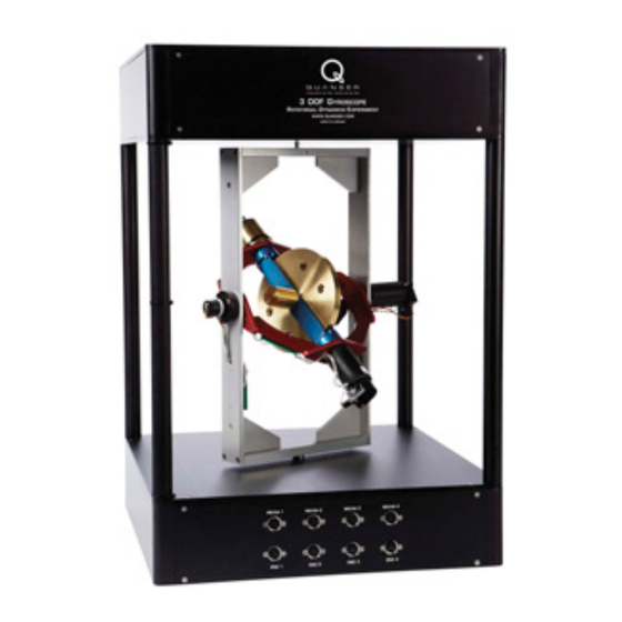
1. 3 DOF Gyroscope
2. Set of three M 4-15mm metric screws;
9/64 Allen key; spacer
3. Set of four 5-pin DIN to 5-pin DIN
encoder cables
4. Quanser Workstation Resources*
(includes controllers; User Manual,
Quick Start Guide and courseware;
and other fi les)
*Download the student version from the
RCP Toolkit Resources at www.ni.com
labviewtools/rcp. For the full instructor
version, contact quanser@ni.com
Advertisement

Related Manuals for Quanser 3 DOF Gyroscope


Summary of Contents for Quanser 3 DOF Gyroscope
- Page 1 CaptiVate. MotiVate. graduate. STEP 2 Additional Components Required for Set Up To complete the 3 DOF Gyroscope experiment set up, you will also need the following: 1. Quanser Rapid Control Prototyping Toolkit for NI LabVIEW™. Visit www.ni.com/labviewtools/rcp RCP Toolkit 2.
- Page 2 STEP 4 Follow the procedure below to set up your 3 DOF Gyroscope experiment. The connections shown below are illustrated using a generic data acquisition (DAQ) device and an AMPAQ-L4 amplifier (you may have a different DAQ or amplifier). For detailed instructions, see the 3 DOF Gyroscope User Manual Make sure everything is powered off...
- Page 3 STEP 5 Testing the 3 DOF Gyroscope Follow the procedure below to test your 3 DOF Gyroscope experiment. Open the LabVIEW ™ Project Make sure your Download the Quanser Workstation Resources fi le (.lvproj) found under the PC and amplifi er (www.ni.com/labviewtools/rcp) and locate the...
- Page 4 Please review the following recommendations before contacting Quanser’s technical support engineers. 1. Make sure the cables are firmly connected. 2. Refer to the Troubleshooting Guide in the 3 DOF Gyroscope User Manual. Make sure you installed all the LabVIEW ™...
Need help?
Do you have a question about the 3 DOF Gyroscope and is the answer not in the manual?
Questions and answers