Table of Contents
Advertisement
Quick Links
Advertisement
Chapters
Table of Contents

Related Manuals for Acer V35N


Summary of Contents for Acer V35N
- Page 1 V35N System User’s Guide...
- Page 2 Copyright Copyright ã 1996 by this company. All rights reserved. No part of this publication may be reproduced, transmitted, transcribed, stored in a retrieval system, or translated into any language or computer language, in any form or by any means, electronic, mechanical, magnetic, optical, chemical, manual or otherwise, without the prior written permission of this company.
- Page 3 Other brand and product names are trademarks and/or registered trademarks of their respective holders. IMPORTANT SAFETY INSTRUCTIONS Read these instructions carefully. Save these instructions for future reference. Follow all warnings and instructions marked on the product. Unplug this product from the wall outlet before cleaning. Do not use liquid cleaners or aerosol cleaners.
- Page 4 Do not allow anything to rest on the power cord. Do not locate this product where persons will walk on the cord. 10. If an extension cord is used with this product, make sure that the total ampere rating of the equipment plugged into the extension cord does not exceed the extension cord ampere rating.
- Page 5 14. Replace battery with the same type as the product's battery we recommend. Use of another battery may present a risk of fire or explosion. Refer battery replacement to a qualified serviceman. 15. Warning! Battery may explode if not handled properly. Do not recharge, disassemble or dispose of in fire.
- Page 6 FCC Class B Radio Frequency Interference Statement Note: This equipment has been tested and found to comply with the limits for a Class B digital device, pursuant to Part 15 of FCC Rules. These limits are designed to provide reasonable protection against harmful interference in a residential installation.
- Page 7 Notice 2: Shielded interface cables, if any, must be used in order to comply with the emission limits.
- Page 8 About this Manual Purpose This user’s guide gives you all the information you need to operate the system properly. Manual Structure This user’s guide consists of two chapters as follows: Chapter 1 System Board This chapter describes the system board and all its major components.
- Page 9 Conventions The following conventions are used in this manual: Represents text input by the user. Text entered by user Denotes actual messages that Screen messages appear onscreen. Represent the actual keys that you , etc. have to press on the keyboard. NOTE Gives bits and pieces of additional information related to the current...
- Page 10 through little shortcuts.
-
Page 11: Table Of Contents
Table of Contents Chapter 1 System Board System Board Layout..........1-2 ESD Precautions............1-4 Pre-installation Instructions........1-4 Installing a CPU............1-5 1.4.1 Installation Procedures........1-5 1.4.2 Installing an OverDriveä CPU.....1-6 Jumpers and Connectors...........1-7 Installing Memory.............1-11 1.6.1 Installing a SIMM........1-13 1.6.2 Removing a SIMM........1-14 1.6.3 Reconfiguring the System......1-14 Upgrading the Second-level Cache......1-15 Installing ISA Cards..........1-16 Post-installation Instructions........1-17... - Page 12 2.2.2 Diskette Drives..........2-5 2.2.3 IDE Drives...........2-6 2.2.4 Total Memory..........2-7 2.2.5 Enhanced IDE Features......2-8 2.2.6 Large Memory Support Mode......2-9 2.2.7 Num Lock After Boot........2-9 2.2.8 Memory Test..........2-9 2.2.9 Quiet Boot...........2-9 2.2.10 Configuration Table........2-10 Advanced System Configuration......2-11 2.3.1 Internal Cache (CPU Cache).....2-12 2.3.2 External Cache..........2-12 2.3.3...
- Page 13 2.4.5 Reset Resources Assignment....2-17 Power Saving Configuration........2-18 2.5.1 Power Management Mode......2-19 2.5.2 Monitored Activities........2-20 System Security Setup..........2-21 2.6.1 Disk Drive Control........2-21 2.6.2 Onboard Communication Ports....2-23 2.6.3 Onboard PS/2 Mouse (IRQ 12)....2-26 2.6.4 Setup Password........2-26 2.6.5 Power On Password.........2-29 Load Setup Default Settings........2-30 Leaving Setup............2-31 List of Figures System Board Layout..........1-3...
- Page 14 Second-level Cache Size Select........1-9 Onboard Connectors..........1-10 Memory Configurations..........1-11 System Error Messages...........1-18 Drive Control Settings..........2-22 Serial Port 1 Settings..........2-23 Serial Port 2 Settings..........2-24 Parallel Port Settings..........2-24 Parallel Port Operation Mode Settings.....2-25...
-
Page 15: Chapter 1 System Board
C h a p t e r System Board This high-performance system board utilizes a 64-bit, 3.3V Intel Pentium â CPU running at 75/50, 90/60, 100/66, 120/60, 133/66, 150/60, 166/66, or 200/66 MHz. It has three ISA and four PCI slots (with one PCI- and ISA- shared slot) for future expansion. -
Page 16: System Board Layout
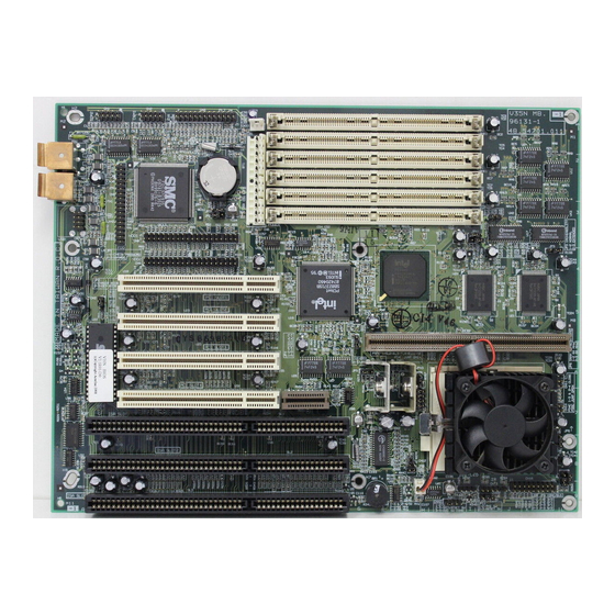
System Board Layout The system board has the following features and components: · Supports 3.3V Intel Pentium CPU (75/50, 90/60, 100/66, 120/60, 133/66, 150/60, 166/66, 200/66 MHz) · 192-MB maximum system memory · Six 72-pin SIMM sockets that accept 4-, 8-, 16-, and 32-MB SIMMs, with or without Extended Data Output (EDO) and Error Checking and Correction (ECC) functions ·... -
Page 17: System Board Layout
Super I/O controller Ether-SCSI card slot RTC battery PCI slots SIMM sockets ISA slots Tag RAM BIOS chip 256-KB pipelined-burst cache PS/2 mouse connector Cache module socket PS/2 keyboard connector CPU socket Voltage regulators with heatsink Figure 1-1 System Board Layout The heatsink becomes very hot when the system is on. -
Page 18: Esd Precautions
ESD Precautions Electrostatic discharge (ESD) can damage your processor, disk drives, expansion boards, and other components. Always observe the following precautions before you install a system component. Do not remove a component from its protective packaging until you are ready to install it. Wear a wrist grounding strap and attach it to a metal part of the system unit before handling components. -
Page 19: Installing A Cpu
Installing a CPU 1.4.1 Installation Procedures Observe the ESD precautions when installing components. See section 1.2. The system board features a zero-insertion force (ZIF) socket for easy CPU installation. Follow these steps to install a CPU: Pull up the socket lever. Insert the CPU, making sure that pin 1 (indicated by a notched corner) of the CPU connects to hole 1 of the socket. -
Page 20: Installing An Overdriveä Cpu
1.4.2 Installing an OverDriveä CPU The OverDrive CPU comes with a heatsink already mounted. To maintain proper airflow around the CPU and heatsink, follow the required clearances in Table 1-1. Table 1-1 Clearances for OverDrive CPU and Heatsink Location Minimum Clearance Above the heatsink 0.4 inches Sides of the CPU (at least 3 of 4) -
Page 21: Jumpers And Connectors
Jumpers and Connectors Figure 1-4 shows the jumper and connector locations. Figure 1-4 Jumper and Connector Locations The shaded pin indicates pin 1. System Board... -
Page 22: System Board Jumper Settings
The following tables list the jumper settings and their corresponding functions: Table 1-2 System Board Jumper Settings Jumper Setting Function Check password Bypass password 64-MB cacheable memory 2-3 * 512-MB cacheable memory 3.3V operating voltage 2-3 * 3.6V operating voltage 60 MHz DRAM refresh rate 2-3 * 66 MHz DRAM refresh rate... -
Page 23: Cpu Frequency Select
Table 1-4 CPU Frequency Select CN12 CPU Freq. 1-3, 2-4 75 MHz 90 MHz 100 MHz 120 MHz 133 MHz 150 MHz 166 MHz 200 MHz Table 1-5 Second-level Cache Size Select JPX1 Cache Size Disable cache 2-3 * 1-2 * 256 KB 512 KB Reserved... -
Page 24: 20-Pin Multifunction Connector (Cn16)
Table 1-6 lists the onboard connectors. Table 1-6 Onboard Connectors Connector Function COM1 connector COM2 connector Parallel connector FDD connector Power connector USB connector HDD1 connector HDD2 connector CN13 Infrared (IR) function connector CN15 IDE LED connector CN16 Multifunction connector Two-pin fan connector The multifunction connector CN16 accommodates the front panel connectors for speaker, LEDs, keylock, reset, and turbo. -
Page 25: Installing Memory
Installing Memory The system memory is expandable to 192 MB by adding single in-line memory modules (SIMMs). See Figure 1-1 for the location of the SIMM sockets. Section 1.6.1 tells how to install SIMMs. The six 72-pin SIMM sockets on the system board accept single- (4- and 8-MB) and double-density (16- and 32-MB) SIMMs, with 60 ns or less DRAM speed. - Page 26 Slot 1 Slot 2 Slot 3 Slot 4 Slot 5 Slot 6 Memory 16 MB 16 MB 16 MB 16 MB 8 MB 8 MB 80 MB 16 MB 16 MB 16 MB 16 MB 16 MB 16 MB 96 MB 32 MB 32 MB 64 MB...
-
Page 27: Installing A Simm
1.6.1 Installing a SIMM Observe the ESD precautions when installing components. See section 1.2. Follow these steps to install a SIMM: Carefully slip a SIMM at a 45° angle into a socket making sure that the curved edge indicating the pin 1 of the SIMM matches pin 1 of the socket. -
Page 28: Removing A Simm
See section 1.9 for the post-installation instructions. 1.6.2 Removing a SIMM Follow these steps to remove a SIMM: Press the holding clips on both sides of the SIMM outward to release it. Move the SIMM to a 45° angle. Pull the SIMM out of the socket. Holding Clip Figure 1-7 Removing a SIMM... -
Page 29: Upgrading The Second-Level Cache
Upgrading the Second-level Cache Observe ESD precautions when installing components. See section 1.2. The system board comes with 256-KB second-level pipelined-burst cache and a cache module socket. The cache socket allows you to upgrade the second-level cache to 512-KB. See Figure 1-1 for the location of the 256- KB pipelined-burst cache and the cache module socket. -
Page 30: Installing Isa Cards
Installing ISA Cards Both PnP and non-PnP ISA cards require specific IRQs. When installing ISA cards, make sure that the IRQs required by these cards are not previously assigned to PCI devices to avoid resource conflicts. Follow these steps when installing ISA cards: Remove all PnP cards installed in the system, if any. -
Page 31: Post-Installation Instructions
Post-installation Instructions Observe the following after installing a system component: See to it that the components are installed according to the step-by-step instructions in their respective sections. Make sure you have set all the required jumpers. See section 1.5 for the correct jumper settings. -
Page 32: System Error Messages
system prompt appears. Table 1-8 lists the system error messages in alphabetical order. Table 1-8 System Error Messages Error Message Corrective Action Bad CMOS Battery Replace battery. Contact your dealer. CMOS Checksum Error Run Setup. Diskette Drive Controller Check and connect the cable to the diskette Error drive or controller. -
Page 33: Correcting Error Conditions
Table 1-8 System Error Messages (continued) Error Message Corrective Action Keyboard Locked Unlock the keyboard. Memory Error Check SIMMs on the system board. Contact your dealer. Memory Size Mismatch Run Setup. Serial 1 Conflict Run Setup. Disable Onboard Serial 1. Serial 2 Conflict Run Setup. - Page 34 Run Setup. You must know the correct configuration values for your system before you enter Setup, which is why you should write these values down when the system is correctly configured. An incorrect Setup configuration is a major cause of power-on error messages, especially for a new system.
-
Page 35: Chapter 2 Bios Utility
C h a p t e r BIOS Utility Most systems are already configured by the manufacturer or the dealer. There is no need to run Setup when starting the computer unless you get a Run Setup message. The Setup program loads configuration values into the battery-backed nonvolatile memory called CMOS RAM. -
Page 36: Entering Setup
Entering Setup To enter Setup, press the key combination You must press while the system is booting. This key combination does not work during any other time. The BIOS Utility main menu then appears: BIOS Utility Basic System Configuration Advanced System Configuration PnP/PCI System Configuration Power Saving Configuration System Security... - Page 37 user-configurable. BIOS Utility...
- Page 38 Basic System Configuration Select Basic System Configuration to input configuration values such as date, time, and disk types. The following screen shows the Basic System Configuration menu. Basic System Configuration Page 1/2 Date ......[MM/DD/YY] Time ......[HH:MM:SS] Diskette Drive A ..[xx-MB xx-inch] Diskette Drive B ..[xx-MB xx-inch]...
-
Page 39: Date And Time
The following screen shows page 2 of the Basic System Configuration menu. Basic System Configuration Page 2/2 Enhanced IDE Features Hard Disk Block Mode ...[Enabled ] Advanced PIO Mode ....[Enabled ] Hard Disk Size > 504MB ..[Enabled ] Hard Disk 32-Bit Access ..[Enabled ] Large Memory Support Mode ..[Normal Num Lock After Boot ....[Enabled ] Memory Test .......[Disabled]... -
Page 40: Diskette Drives
Valid values for month, day, and year are: · Month · · Year Time Highlight the items on the time parameter and press to set the time following the hour-minute-second format. Valid values for hour, minute, and second are: · Hour ·... -
Page 41: Ide Drives
2.2.3 IDE Drives Move the highlight bar to the IDE Drive 0 parameter to configure the first IDE drive (drive C). Press to display the IDE drive types with their respective values. Select the type that corresponds to your IDE hard disk drive. Follow the same procedure for the other IDE drives, if any. - Page 42 Follow the same procedure to auto-configure other IDE drives. User’s Guide...
-
Page 43: Total Memory
Selecting the “User” Option There are cases when you cannot use the option Auto , instead you have to select User . Choose the User option when you have installed an IDE hard disk that was previously formatted but does not use the disk native parameters or structure, that is, the disk type may be in the IDE hard disk types list but the number of cylinders, heads, and sectors differ. -
Page 44: Enhanced Ide Features
2.2.5 Enhanced IDE Features Hard Disk Block Mode This function enhances disk performance depending on the hard disk in use. If you set this parameter to Enabled , it allows data transfer in block (multiple sectors) by increasing the data transfer rate to 256 bytes per cycle. -
Page 45: Large Memory Support Mode
2.2.6 Large Memory Support Mode The available settings for this parameter are Normal Advanced Set this parameter to Advanced if you are working under Windows NT 3.1 environment. The setting allows you to support an extended Normal memory higher than 64 MB. The default setting is 2.2.7 Num Lock After Boot This parameter allows you to activate the Num Lock function upon... -
Page 46: Configuration Table
2.2.10 Configuration Table This parameter allows you to display the configuration table after POST but before booting. The configuration table gives a summary of the hardware devices and settings that BIOS detected during POST. A sample configuration table appears below. CPU ID Pentium Base Memory:... -
Page 47: Advanced System Configuration
Advanced System Configuration The Advanced System Configuration option allows you to configure the advanced system memory functions. Do not change any settings in the Advanced Configuration if you are not a qualified technician to avoid damaging the system. The following screen shows page one the Advanced System Configuration parameters. -
Page 48: Internal Cache (Cpu Cache)
¯ = Move Highlight Bar, ® ¬ = Change Setting PgDn/PgUp = Move Screen, F1 = Help, Exit 2.3.1 Internal Cache (CPU Cache) This parameter enables or disables the first-level cache memory. The default setting is Enabled 2.3.2 External Cache This parameter enables or disables the second-level cache memory. -
Page 49: Memory At 15Mb - 16Mb
2.3.6 Memory at 15MB - 16MB This parameter allows you to reserve a memory range for the use of either the system or an expansion board to prevent memory address conflicts. Before setting this parameter, check your add-on card manual to determine if your add-on card needs this memory space. -
Page 50: Dram Write Burst Timing
2.3.9 DRAM Write Burst Timing This parameter adjusts the write wait-state between the L2 and the DRAM cache. The L2 cache is processed through write-back method and each cache write process consists of four continuous cache write cycles. Therefore, this setting has four numbers to adjust. The available settings are X-4-4-4, X-3-3-3, X-2-2-2... -
Page 51: Pci System Configuration
PCI System Configuration The PCI System Configuration allows you to specify the settings for your PCI devices. PCI System Configuration Page 1/1 PCI IRQ Setting ....[ Auto INTA INTB INTC INTD *PCI Slot 1....[--] [--] [--] [--] *PCI Slot 2....[--] [--] [--] [--]... -
Page 52: Pci Irq Sharing
PCI Slots These parameters allow you to specify the appropriate interrupt for each of the PCI devices. You can assign IRQ5, IRQ9, IRQ10, IRQ11, IRQ15 to the slots. Press to move between fields. Press to select options. 2.4.2 PCI IRQ Sharing Setting this parameter to allows you to assign the same IRQ to two different devices. -
Page 53: Plug & Play Os
2.4.4 Plug & Play OS When this parameter is set to , BIOS initializes only PnP boot devices such as SCSI cards. When set to , BIOS initializes all PnP boot and non-boot devices such as sound cards. Set this parameter to only if your operating system is Windows 95. -
Page 54: Power Saving Configuration
Power Saving Configuration The Power Saving Configuration parameters are configurable only if your system supports the power management feature. The following screen shows the Power Saving Configuration parameters and their default settings: Power Saving Configuration Page 1/1 Power Management Mode ....[Enabled ] IDE Hard Disk Standby Timer ..[15] Minute(s) System Standby Timer ....[15] Minute(s) System Suspend Timer ....[15] Minute(s) -
Page 55: Power Management Mode
2.5.1 Power Management Mode This parameter allows you to reduce power consumption. When this parameter is set to Enabled , you can configure the IDE hard disk and system timers. Setting to Disabled deactivates the power management feature and all the timers. IDE Hard Disk Standby Timer This parameter allows the hard disk to enter standby mode after inactivity of 1 to 15 minutes, depending on your setting. -
Page 56: Monitored Activities
2.5.2 Monitored Activities The IRQ items under this parameter allow you to monitor system activities occurring through the IRQ channels to determine whether or not to enter power saving mode. For example, if you assign IRQ 3 to a fax/modem and you set this item Enabled , any fax/modem activity wakes up the system from standby mode. -
Page 57: System Security Setup
System Security Setup The Setup program has a number of security features to prevent unauthorized access to the system and its data. The following screen appears if you enter the Setup program and select System Security. System Security Page 1/1 Disk Drive Control Diskette Drive....[ Normal... -
Page 58: Drive Control Settings
Table 2-1 Drive Control Settings Diskette Drive Setting Description Normal Diskette drive functions normally Write Protect All Sectors Disables the write function on all sectors Write Protect Boot Sector Disables the write function only on the boot sector Disabled Disables all diskette functions Hard Disk Drive Setting Description... -
Page 59: Onboard Communication Ports
Table 2-1 Drive Control Settings (continued) Boot from CD-ROM Setting Description Enabled The system checks for a bootable CD in the CD-ROM. If a CD is present, the system boots from the CD-ROM. Otherwise, it boots from the drive specified in the System Boot drive parameter. -
Page 60: Serial Port 2 Settings
Serial Port 2 Base Address This parameter allows you to set the serial port 2 logical base address. Table 2-3 Serial Port 2 Settings Setting Description 3F8h Serial port 2 with address 3F8h using IRQ4 2F8h Serial port 2 with address 2F8h using IRQ3 3E8h Serial port 2 with address 3E8h using IRQ4 2E8h... -
Page 61: Parallel Port Operation Mode Settings
Disabled To deactivate the parallel port, select the option. If you install an add-on card that has a parallel port whose address conflicts with the parallel port onboard, the system automatically disables the onboard functions. Check the parallel port address on the add-on card and change the address to one that does not conflict. -
Page 62: Onboard Ps/2 Mouse (Irq 12)
2.6.3 Onboard PS/2 Mouse (IRQ 12) This parameter enables or disables the onboard PS/2 mouse. When set to Enabled , it allows you to use the onboard PS/2 mouse assigned with IRQ12. When set to Disabled , it deactivates the mouse and makes IRQ12 available for use of other devices. - Page 63 Press . A prompt asks you to retype the password to verify your first entry. Retype the password then press After setting the password, the system automatically sets the Setup Password parameter to Present Press to exit the System Security screen and return to the main menu.
- Page 64 Changing or Removing the Setup Password Should you want to change your setup password, do the following: Enter the BIOS utility and select System Security. Highlight the Setup Password parameter. Press to display the password prompt and key-in a new password.
-
Page 65: Power On Password
You can either change the existing Setup password or remove it by selecting None Refer to the previous section for the procedure. 2.6.5 Power On Password The Power On Password secures your system against unauthorized use. Once you set this password, you have to type it whenever you boot the system. -
Page 66: Load Setup Default Settings
Load Setup Default Settings Use this option to load the default settings for the optimized system configuration. When you load the default settings, some of the parameters are grayed-out with their fixed settings. These grayed parameters are not user-configurable. The following dialog box appears when you select Load Setup Default Settings from the main menu. -
Page 67: Leaving Setup
Leaving Setup Examine the system configuration values. When you are satisfied that all the values are correct, write them down. Store the recorded values in a safe place. In the future, if the battery loses power or the CMOS chip is damaged, you will know what values to enter when you rerun Setup.