Table of Contents
Advertisement
Quick Links
Advertisement
Table of Contents

Related Manuals for National Instruments PXI-7340


Summary of Contents for National Instruments PXI-7340
- Page 1 PXI-7342...
- Page 2 Motion Control National Instruments 7340 User Manual and Specifications NI 7340 User Manual and Specifications March 2013 370838B-01...
- Page 3 For further support information, refer to the Technical Support and Professional Services appendix. To comment on National Instruments documentation, refer to the National Instruments Web site at ni.com/info and enter the Info Code feedback. © 2003–2013 National Instruments. All rights reserved.
- Page 4 National Instruments Corporation. National Instruments respects the intellectual property of others, and we ask our users to do the same. NI software is protected by copyright and other intellectual property laws. Where NI software may be used to reproduce software or other materials belonging to others, you may use NI software only to reproduce materials that you may reproduce in accordance with the terms of any applicable license or other legal restriction.
- Page 5 ™ The ExpressCard word mark and logos are owned by PCMCIA and any use of such marks by National Instruments is under license. The mark LabWindows is used under a license from Microsoft Corporation. Windows is a registered trademark of Microsoft Corporation in the United States and other countries.
-
Page 6: Table Of Contents
Features........................1-1 Hardware ........................1-1 RTSI.......................... 1-2 What You Need to Get Started ..................1-2 Software Programming Choices..................1-2 National Instruments Application Software ..............1-3 Optional Equipment......................1-3 Motion I/O Connections ....................1-3 Related Documentation ....................4 Chapter 2 Configuration and Installation Software Installation...................... - Page 7 Contents Chapter 4 Signal Connections Motion I/O Connector....................... 4-1 Motion Axis Signals ....................4-4 Step, Direction, and Inhibit Output Circuit............4-5 Limit and Home Inputs ..................... 4-5 Wiring Concerns ....................4-6 Limit and Home Input Circuit ................4-6 Encoder Signals ......................4-7 Encoder <1..4>...
-
Page 8: About The Ni 7340 Motion Controller
Introduction This chapter includes information about the features of the National Instruments PXI/PCI-7340 motion controller and information about operating the device. About the NI 7340 Motion Controller The NI 7340 motion controller features advanced motion control with easy-to-use software tools and add-on motion VI libraries for use with LabVIEW. -
Page 9: Rtsi
RTSI The NI 7340 motion controller supports the National Instruments Real-Time System Integration (RTSI) bus. The RTSI bus provides high-speed connectivity between National Instruments products, including image acquisition (IMAQ) and data acquisition (DAQ) products. Using the RTSI bus, you can easily synchronize several functions to a common trigger or timing event across multiple motion, IMAQ, or DAQ devices. -
Page 10: National Instruments Application Software
When you have created a motion task, you can use Motion Assistant to output the task in LabVIEW or C code or code recipes. Optional Equipment National Instruments offers a variety of products for use with the NI 7340 motion controller, including the following accessories: •... -
Page 11: Related Documentation
Chapter 1 Introduction Related Documentation The following documents contain information you might find helpful as you read this manual: • NI-Motion Help • NI-Motion C Reference Help • NI-Motion VI Help 1-4 | ni.com... -
Page 12: Configuration And Installation
Because motion I/O-related configuration of the NI 7340 motion controller is performed entirely with software, it is not necessary to set jumpers for motion I/O configuration. The PXI-7340 and PCI-7340 controllers are fully compatible with the industry standard PXI Specification, Revision 2.0 and the PCI Local Bus Specification, Revision 2.2, respectively. - Page 13 Chapter 2 Configuration and Installation Do not substitute parts or modify the hardware except as described in this document. Use the hardware only with the chassis, modules, accessories, and cables specified in the installation instructions or specifications. You must have all covers and filler panels installed during operation of the hardware.
-
Page 14: Electromagnetic Compatibility Information
Furthermore, any modifications to the product not expressly approved by National Instruments could void your authority to operate it under your local regulatory rules. -
Page 15: Pxi Motion Controllers
Chapter 2 Configuration and Installation Caution The NI 7340 motion controller is a sensitive electronic device shipped in an antistatic bag. Open only at an approved workstation and observe precautions for handling electrostatic-sensitive devices. Note When adding or removing a motion controller, you must be logged on with administrator-level access. -
Page 16: Pci Motion Controllers
Always power on the computer containing the NI 7340 motion controller and then initialize the controller before you power on the rest of the motion system. Power off the motion system in the reverse order. Plug in and power on the computer. © National Instruments | 2-5... -
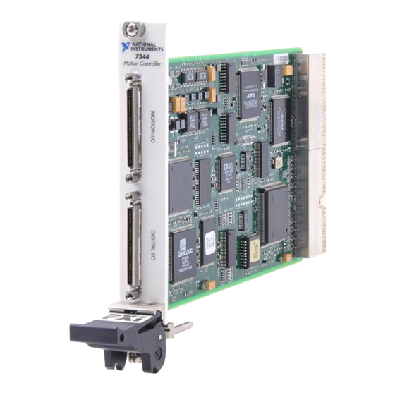
Page 17: Hardware Overview
Hardware Overview This chapter presents an overview of the National Instruments PXI/PCI-7340 hardware functionality. Figures 3-1 and 3-2 show the NI PXI-7340 right and left sides, respectively. Figure 3-1. NI PXI-7340 Right Side Serial Number Label 68-Pin Digital I/O Connector... - Page 18 Chapter 3 Hardware Overview Figure 3-2. NI PXI-7340 Left Side N114 Identification Number Used in Australia Assembly Number Label Symbol Indicating FFC Compliance Symbol to Alert User to Read the Manual Board Type Label 3-2 | ni.com...
-
Page 19: User Connectors
Connections, for details about the signals in the digital I/O connector. The PCI-7340 RTSI connector provides up to eight triggers to facilitate synchronization between multiple National Instruments products. The PXI-7340 RTSI-enabled connection provides up to eight triggers and one PXI star trigger to facilitate synchronization between multiple National Instruments PXI-enabled products. -
Page 20: Functional Overview
Chapter 3 Hardware Overview Functional Overview This section provides an overview of motion control algorithms and the NI PXI/PCI-7340 controller. Dual Processor Architecture With the NI 7340 motion controller, you can perform up to four axes of simultaneous, coordinated motion control in a preemptive, multitasking, real-time environment. An advanced dual-processor architecture that uses a 32-bit CPU combined with a digital signal processor (DSP) and custom FPGAs give the NI 7340 motion controller high-performance capabilities. -
Page 21: Analog Feedback
At a minimum, an axis consists of a trajectory generator, a PID (for servo axes) or stepper control block, and at least one output resource—either a DAC output (for servo axes) or a stepper pulse generator output. Servo axes must have either an encoder or ADC channel feedback resource. © National Instruments | 3-5... -
Page 22: Motion Resources
Chapter 3 Hardware Overview Closed-loop stepper axes also require a feedback resource, while open-loop stepper axes do not. Figures 3-4 and 3-5 show these axis configurations. With the NI 7340 motion controller, you can map one or two feedback resources and one or two output resources to the axis. -
Page 23: Onboard Programs And Buffers
The communications status register (CSR) provides bits for communications handshaking as well as real-time error reporting and general status feedback to the host PC. The move complete status (MCS) register provides instantaneous motion status of all axes. © National Instruments | 3-7... -
Page 24: Signal Connections
• Forward, home, and reverse limit inputs • Breakpoint outputs • Trigger inputs • Inhibit outputs The motion I/O connector also contains four channels of 12-bit A/D inputs for analog feedback or general-purpose analog input. © National Instruments | 4-1... - Page 25 Chapter 4 Signal Connections Figure 4-1 shows the pin assignments for the 68-pin motion I/O connector on the NI 7340 motion controller. Table 4-1 includes descriptions for each of the signals. A line above a signal name indicates that the signal is active-low. Figure 4-1.
- Page 26 Analog Output Ground — — Reference for analog outputs Shutdown Digital Ground Input Controlled device shutdown Analog Reference (output) Analog Input Output +7.5 V—analog reference Ground level Digital Ground — — Reference for digital I/O © National Instruments | 4-3...
-
Page 27: Motion Axis Signals
Chapter 4 Signal Connections Motion Axis Signals The following signals control the servo amplifier or stepper driver. • Analog Output <1..4>—These 16-bit DAC outputs are typically the servo command outputs for each axis. They can drive the industry-standard ±10 V output, and can be software limited to any positive or negative voltage range. -
Page 28: Step, Direction, And Inhibit Output Circuit
Active signals should remain active to prevent motion from proceeding further into the limit. Pulsed limit signals stop motion, but they do not prevent further motion in that direction if another move is started. © National Instruments | 4-5... -
Page 29: Wiring Concerns
These inputs are part of a system solution for complete motion control. Caution National Instruments recommends using limits for personal safety, as well as to protect the motion system. Wiring Concerns For the end of travel limits to function correctly, the forward limit must be located at the forward or positive end of travel, and the reverse limit at the negative end of travel. -
Page 30: Encoder Signals
Encoder Signals The NI 7340 motion controller offers four channels of single-ended quadrature encoder inputs. All National Instruments power drives and UMI accessories provide built-in circuitry that converts differential encoder signals to single-ended encoder signals. Each channel consists of a Phase A, Phase B, and Index input, as described in the following sections. -
Page 31: Encoder <1
Cables with twisted pairs and an overall shield are recommended for optimized noise immunity. All National Instruments power drives and UMI accessories provide built-in circuitry that converts differential encoder signals to single-ended encoder signals. -
Page 32: Encoder Input Circuit
You can program breakpoints as absolute, modulo, or relative positions. Breakpoint outputs can be preset to a known state so that the transition when the breakpoint occurs can be low to high, high to low, or toggle. © National Instruments | 4-9... -
Page 33: Wiring Concerns
Chapter 4 Signal Connections The breakpoint outputs are driven by open-collector TTL buffers that feature 64 mA sink current capability and built-in 3.3 kΩ pull-up resistors to +5 V. You can directly set and reset breakpoint outputs to use them as general-purpose digital outputs. -
Page 34: Analog Inputs
Binary Values Resolution ±10 V -2,048 to 2,047 0.0049 V/LSB ±5 V -2,048 to 2,047 0.0024 V/LSB 0 to 10 V 0 to 4,095 0.0024 V/LSB 0 to 5 V 0 to 4,095 0.0012 V/LSB © National Instruments | 4-11... -
Page 35: Wiring Concerns
Chapter 4 Signal Connections As indicated in Table 4-3, when configured as analog feedback, an analog sensor acts like a limited range absolute position device with a full-scale position range. You can map any ADC channel as feedback to any axis. You can enable and disable individual ADC channels in software. -
Page 36: Digital I/O Connector
The 32-bit digital I/O port is configured in hardware as four 8-bit digital I/O ports. The bits in a port are typically controlled and read with byte-wide bitmapped commands. All digital I/O lines have programmable direction and polarity. Each output circuit can sink and source 24 mA. © National Instruments | 4-13... -
Page 37: Pwm Features
The physical RTSI bus interface varies depending on the type of NI 7340 motion controller. The PXI-7340 uses the PXI chassis backplane to connect to other RTSI-capable devices. The PCI-7340 uses a ribbon cable to connect to other RTSI-capable PCI devices. -
Page 38: Appendix A Specifications
Resolution ..........16 bits (0.000305 V/LSB) Programmable torque (velocity) limits Positive limit........±10 V (-32,768 to +32,767) Negative limit ........±10 V (-32,768 to +32,767) Programmable offset......... ±10 V (-32,768 to +32,767) Refer to the NI-Motion Help for more information. © National Instruments | A-1... - Page 39 Appendix A Specifications Stepper Performance Trajectory update rate range ......62.5 to 500 µs/sample Maximum update rate .......62.5 µs/axis 4-axis update rate ........250 µs total Multi-axis synchronization .......<1 update sample Double-buffered trajectory parameters Position range ...........±2 steps Maximum relative move size....±2 steps Velocity range ...........1 to 4,000,000 steps/s Acceleration/deceleration...
- Page 40 Output low voltage ......<0.6 V at 64 mA sink Output high voltage ......Open collector with built-in 3.3 kΩ pull-up to +5 V Polarity............Programmable, active-high or active-low Control ............MustOn/MustOff or automatic when axis off © National Instruments | A-3...
- Page 41 Appendix A Specifications Analog inputs Number of inputs ........8, multiplexed, single ended Number for user signals ....4 Number for system diagnostics ..4 Voltage range (programmable) ....Programmable: ±10 V, ±5 V, 0 to 10 V, 0-5 V Input coupling ...........DC Input resistance .........10 kΩ min Resolution ..........12 bits, no missing codes Monotonocity..........Guaranteed Multiplexor scan rate ........25 µs/enabled channel...
- Page 42 -12 V (±10%)............ 30 mA Power consumption .......... 5.7 W Physical Dimensions (Not Including Connectors) PXI-7340 ............16 × 10 cm (6.3 × 3.9 in.) PCI-7340............17.5 × 9.9 cm (6.9 × 3.9 in.) Connectors Motion I/O connector ........68-pin female high-density VHDCI type 32-bit digital I/O connector ......
- Page 43 Appendix A Specifications Maximum altitude..........2,000 m Pollution Degree ..........2 Indoor use only. Safety This product meets the requirements of the following standards of safety for electrical equipment for measurement, control, and laboratory use: • IEC 61010-1, EN 61010-1 • UL 61010-1, CSA 61010-1 Note For UL and other safety certifications, refer to the product label or the Online...
- Page 44 At the end of the product life cycle, all products must be sent to a WEEE recycling center. For more information about WEEE recycling centers, National Instruments WEEE initiatives, and compliance with WEEE Directive 2002/96/EC on Waste and Electronic Equipment, visit ni.com/environment/...
- Page 45 43 44 Axis 4 Home Switch Axis 4 Encoder Index 45 46 Axis 4 Forward Limit Switch Trigger/Breakpoint 4 47 48 Axis 4 Reverse Limit Switch Axis 4 Inhibit 49 50 Digital Ground Host +5 V © National Instruments | B-1...
- Page 46 Appendix B Cable Connector Descriptions Figure B-2. 50-Pin Servo Connector Pin Assignment Analog Output Ground Analog Output 1 Axis 1 Encoder Phase A Digital Ground Digital Ground Axis 1 Encoder Phase B Axis 1 Encoder Index Axis 1 Home Switch Axis 1 Forward Limit Switch Trigger/Breakpoint 1 11 12...
- Page 47 You can also register for instructor-led, hands-on courses at locations around the world. • System Integration—If you have time constraints, limited in-house technical resources, or other project challenges, National Instruments Alliance Partner members can help. To learn more, call your local NI office or visit ni.com/alliance •...
- Page 48 In general, the amplifier is designed to operate with a particular motor type—you cannot use a stepper drive to operate a DC brushed motor, for instance. application programming interface axis Unit that controls a motor or any similar motion or control device. © National Instruments | G-1...
- Page 49 Glossary bit—one binary digit, either 0 or 1. base address Memory address that serves as the starting address for programmable or I/O bus registers. All other addresses are located by adding to the base address. binary A number system with a base of 2. buffer Temporary storage for acquired or generated data (software).
- Page 50 The condition of a motor when power is de-energized and the motor shaft is free to turn with only frictional forces to impede it. full-step Full-step mode of a stepper motor—for a two phase motor this is done by energizing both windings or phases simultaneously. ground © National Instruments | G-3...
- Page 51 Glossary ground half-step Mode of a stepper motor—for a two phase motor this is done by alternately energizing two windings and then only one. In half step mode, alternate steps are strong and weak but there is significant improvement in low-speed smoothness over the full-step mode. hexadecimal home switch (input) A physical position determined by the mechanical system or designer...
- Page 52 Noise corrupts signals you are trying to send or receive. noninverting The polarity of a switch (limit switch, home switch, etc.) in active state. If these switches are active-high, they are said to have non-inverting polarity. © National Instruments | G-5...
- Page 53 Glossary open-loop Refers to a motion control system where no external sensors (feedback devices) are used to provide position or velocity correction signals. peripheral component interconnect—a high-performance expansion bus architecture originally developed by Intel to replace ISA and EISA. It is achieving widespread acceptance as a standard for PCs and workstations;...
- Page 54 RTSI real-time system integration bus—the National Instruments timing bus that connects devices directly, by means of connectors on top of the devices, for precise synchronization of functions. seconds servo Specifies an axis that controls a servo motor.
- Page 55 Glossary volts Positive voltage supply. velocity mode Move the axis continuously at the specified velocity. watchdog A timer task that shuts down (resets) the motion control board if any serious error occurs. word The standard number of bits that a processor or memory manipulates at one time, typically 8-, 16-, or 32-bit.
- Page 56 Declaration of Conformity (NI resources), C-1 diagnostic tools (NI resources), C-1 Analog Input <1..4>, 4-11 documentation Analog Input Ground, 4-12 NI resources, C-1 Analog Output <1..4>, 4-4 related documentation, 1-4 Analog Output Ground, 4-4 drivers (NI resources), C-1 © National Instruments | I-1...
- Page 57 I/O, connector Phase A/Phase B, 4-7 pin assignments, 4-2 encoder signals, ground connections, 4-8 signal descriptions, 4-3 examples (NI resources), C-1 National Instruments support and functional overview services, C-1 buffers, 3-7 host communications, 3-7 onboard programs, 3-7 onboard programs, 3-7...
Need help?
Do you have a question about the PXI-7340 and is the answer not in the manual?
Questions and answers