
Related Manuals for Roger PR301


Summary of Contents for Roger PR301
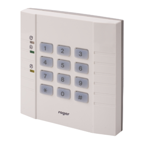
- Page 1 R A C S R o g e r A c c e s s C o n t r o l S y s t e m Access controller with integrated reader and keypad PR301 Version 2.1 Installation and programming manual 02-07-29...
- Page 2 Improvements and modifications in version 2.1 The previous versions of PR301/201 have two modes of operation marked OPEN and CLOSED. The names of those modes have been changed in version 2.1, now OPEN mode is called ON and CLOSED mode is marked OFF. Both modes (ON and OFF) are signalized on one dual colored LED marked ON/OFF.
- Page 3 Operation with remote access terminal One additional access terminal (reader) with ID=0 can be connected to PR301/201 controller. Terminal does not make decision to grant or deny access, terminal reads user identifier (card code, PIN-code or both) than send it to controller which examine codes and grant or deny access for recognized user.
- Page 4 PR301v2.1UK.doc 02-07-29 ! - indicator is on " - indicator is off # - indicator pulses !R - indicator is red !G - indicator is green !R/G - indicator is red or green Acoustic signals SYMBOL OF NAME OF SIGNAL MEANING SIGNAL RESTART...
- Page 5 PR301v2.1UK.doc 02-07-29 by external signal connected to input declared as [Input control ON/OFF mode], automatically by ON/OFF mode schedule declared in software, remotely by interactive command from RACS software. Note: The SWITCH output change its state together with ON/OFF mode of controller, all methods of ON/OFF mode control are also the methods of SWITCH output control.
-
Page 6: User Programming Mode
PR301v2.1UK.doc 02-07-29 User Programming Mode In order to enter User Programming mode do the following sequence: • When controller stand in ON or OFF mode, • [Enter MASTER ident.] • [Wait until LED OPEN start blink] • [Enter MASTER ident. again Note: When [Dual identification mode] is activated operator must enter code and card (no mater what sequence) at first time but at second time only code or card is required. - Page 7 PR301v2.1UK.doc 02-07-29 [7] – D NORMAL SWITCHER ELETES ALL USERS + [#] + [7] + [#] Note: The MASTER and INSTALLER identifiers remain. [8] – E NTRY TO THE NSTALLER ROGRAMMING Note: After EEPROM memory RESET the MASTER and also performs the function of the INSTALLER identifier (MASTER = INSTALLER).
-
Page 8: Installer Programming Mode
PR301v2.1UK.doc 02-07-29 Installer Programming mode In the Installer programming mode detailed setup of controller is available. Entry to the installer programming mode can be done only from the User Programming mode by activation of function [8]. After entry to the Installer Programming mode the SYSTEM and CLOSED LED are on. - Page 9 PR301v2.1UK.doc 02-07-29 [4] - U SER IDENTIFICATION MODES + [OPTION] [0] ⇒ The DUAL identification mode off. [1] ⇒ The DUAL identification mode for NORMAL users [2] ⇒ The DUAL identification mode for MASTER users [3] ⇒ The DUAL identification mode for NORMAL and MASTER [4] ⇒...
-
Page 10: Technical Data
PR301v2.1UK.doc 02-07-29 [9] - P MASTER ROGRAMMING OF IDENTIFIER + [MASTER code] + [#] + [MASTER code] + [#] + [MASTER card] Note: The controller does not require programming of both identification forms, i.e. code and card, programming of the code or card can be skipped (see examples as in function [8]) EEPROM RESET –... -
Page 11: Installation Recommendations
PR301v2.1UK.doc 02-07-29 Installation The controller should be hung near the controlled passage, far from any sources of heat and moisture. Electric connections should be made with the power supply off according to the drawings shown at the end of this manual. After the first time power supply is switched on, the controller wake in OFF (red) mode with pre-programmed MASTER card and default settings. -
Page 12: Off Mode
POWER RETURN TO DEFAULT SETTINGS ENTER “MASTER” INDENTIFIER: DATA IN PRESS EEPROM RESET EEPROM UNTIL DATA ERROR [MASTER code]+[#]+ MEMORY LED OPEN STARTS BLINK - - - - - etc. [MASTER code]+[#]+ O.K. ? (approx. 6 second) [MASTER card] RESTART ON/OFF OFF MODE IDENTIFIER... -
Page 13: User Programming
Exit from PROOGRAMMING MODE ON/OFF ON/OFF USER INSTALLER OPEN OPEN Entry PROGRAMMING PROGRAMMING to the SYSTEM SYSTEM USER PROGRAMING MODE ADD “NORMAL” USER IN 1 INPUT FUNCTION [1] + [ xyz ] + [#] + [ xyz ] + [#] + [1] + [OPTION] [code] + [#] + [code] + [#] + [card] IN 2 INPUT FUNCTION... -
Page 14: Eeprom Reset
2. Max. Distance between controller and terminal 300m. 3. The supply voltage reduction between controler (terminal) and power supply should not exceed 1.0V 4. Electric lock should be supplied using separate wires. Typical connection diagram of PR301/201 access controller. PR_033UK.cdr... - Page 15 POWER SUPPLY 12Vdc e.g. PS10/20 + 12V PRxx1 Access Controller DOOR TAMPER RS 485 IN 3 IN 2 IN 1 12 V SHLD MASTER UT-2 SLAVE PR Master POWER komputer PC Software RS 232 PC COMPUTER COM 1...COM 4 Max 15 m Downloading PR controllers from PC...
- Page 16 NOTE: PR system communication bus - max. length 1000m. GND terminals of each supply units Twisted pair of wires without shielding are preffered. Shielded cabels can only be used where strong must be connected with additional wire. electric interferences exists. SUPPLY ZONE B POWER SUPPLY...
- Page 17 R o g e r A c c e s s C o n t r o l S y s t e m T h e s t r u c t u r e a c c e s s c o n t r o l s y s t e m R A C S 3 .
- Page 18 ID selection (valid only for PRT31 terminal) Drilling template 80 mm Optional 60 mm diameter ON/OFF OPEN SYSTEM 104 mm 16 mm 16 mm The front and side view of PR301 controller and PRT31 terminal. Scale 1 : 1 Cdr090EN...
Need help?
Do you have a question about the PR301 and is the answer not in the manual?
Questions and answers