Table of Contents
Advertisement
Advertisement
Table of Contents

Related Manuals for Toshiba RAV-GM802ATW-E


Summary of Contents for Toshiba RAV-GM802ATW-E
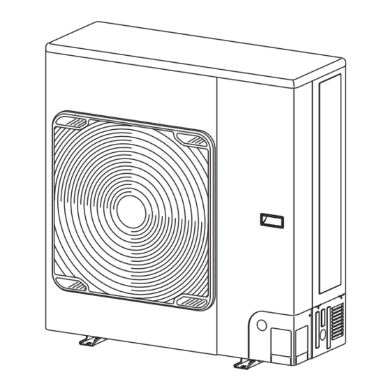
- Page 1 AIR CONDITIONER (SPLIT TYPE) Installation Manual For commercial use Outdoor Unit Model name: <Single-phase model> RAV-GM802ATW-E RAV-GM902ATW-E RAV-GM1102ATW-E RAV-GM1402ATW-E RAV-GM1602ATW-E <Three-phase model> RAV-GM1102AT8W-E RAV-GM1402AT8W-E RAV-GM1602AT8W-E English...
-
Page 2: Table Of Contents
Ssc (*1) Ssc (*1) (kVA) 9 Finishing ........................23 Model Single system Twin system Triple system 10 Test run ........................24 RAV-GM802ATW-E RAV-GM902ATW-E 11 Annual maintenance ....................25 RAV-GM1102ATW-E 12 Air conditioner operating conditions ............... 25 RAV-GM1402ATW-E RAV-GM1602ATW-E 1320 1320 1320 13 Functions to be implemented locally ............... - Page 3 Transportation of heavy objects Shoes with additional protective toecap • The qualified installer is a person who installs, maintains, relocates and removes the Air conditioners made by Toshiba Carrier Air-conditioning Europe Sp. z o.o. He or she has been trained to install, Repair of outdoor unit...
- Page 4 – 3 – ■ Warning indications on the air conditioner unit Warning indication Description These safety cautions describe important matters concerning safety to prevent injury to users or other people and damages to property. Please read through this manual after understanding the contents below (meanings of WARNING indications), and be sure to follow the description.
-
Page 5: Precautions For Safety
Precautions for safety • Only a Qualified installer *(1) or Qualified service person*(1) is allowed to undertake work at heights using a stand of 50 cm or more. The manufacturer shall not assume any liability for the damage caused • Wear protective gloves and safety work clothing during installation, by not observing the description of this manual. - Page 6 – 5 – • Do not use means to accelerate the defrosting process or to clean, • Do not install the air conditioner in a poorly ventilated space that is other than those recommended by the manufacturer. smaller than the minimum floor area (Amin). •...
- Page 7 the refrigeration cycles is over pressurized, which may cause an • Install a circuit breaker that meets the specifications in the installation injury. manual and the stipulations in the local regulations and laws. • Install the circuit breaker where it can be easily accessed by the •...
- Page 8 – 7 – • Upon completion of the installation work, check for refrigerant leaks • When relocating the model GM110, GM140, GM160 unit, use the and check the insulation resistance and water drainage. Then cable ties specified under “How to wire” in Section 7 “Electrical work” conduct a test run to check that the air conditioner is operating or equivalent means to fix the wires to the valve fixing plate.
- Page 9 To disconnect the appliance from main power supply CAUTION • This appliance must be connected to the main power supply by means of a switch with a contact separation of at least 3 mm. This air conditioner adopts the HFC refrigerant (R32) which does not destroy the ozone layer.
- Page 10 – 9 – • The recovered refrigerant shall be returned to the refrigerant supplier in the correct recovery cylinder, and the relevant waste transfer note arranged. • Do not mix refrigerants in recovery units and especially not in cylinders. • If compressors or compressor oils are to be removed, ensure that they have been evacuated to an acceptable level to make certain that flammable refrigerant does not remain within the lubricant.
-
Page 11: Accessory Parts
Installation of R32 refrigerant air conditioner Accessory parts CAUTION Single Three R32 refrigerant air conditioner installation -phase -phase • This air conditioner adopts the HFC refrigerant (R32) which does not destroy ozone layer. Therefore, during installation work, make sure that water, dust, former refrigerant, or refrigerant oil does not enter Part name Shape Usage... -
Page 12: Installation Conditions
– 11 – Installation conditions ■ Refrigerant piping R32 refrigerant ■ Before installation ■ Earthing CAUTION Be sure to prepare to the following items before • Incomplete flaring may cause refrigerant gas leakage. installation. WARNING • Do not re-use flares. Use new flares to prevent Length of refrigerant pipe refrigerant gas leakage. - Page 13 ■ Necessary space for Installation (Unit: mm) CAUTION CAUTION Do not install the outdoor unit in a location that is Single unit installation 1. Install the outdoor unit in a location where the subject to combustible gas leaks. discharge air is not blocked. When there is an obstacle on When there is an obstacle on When there are obstacles on the...
- Page 14 – 13 – ■ Installation of outdoor unit Serial unit installation Correct * When the outdoor temperature is high, the cooling capability may be decreased because of an equipment Absorb vibration • Before installation, check the strength and protection operation. with vibration horizontalness of the base so that abnormal sounds proof rubber...
-
Page 15: Refrigerant Piping
Refrigerant piping ■ For reference • When water is to be drained through the drain hose, attach the following drain nipple and waterproof rubber cap, and use the drain hose (Inner dia.: If a heating operation is to be continuously performed 16 mm) sold on the market. - Page 16 – 15 – ■ Optional Installation parts Flaring ■ Tightening of connecting part <GM110, GM140, GM160> Valve at gas side (Locally procured) 1. Cut the pipe with a pipe cutter. 1. Align the centers of the connecting pipes and fully Be sure to remove burrs that may cause a gas leak.
- Page 17 Simultaneous triple ■ Refrigerant pipe length Allowable pipe length (m) Height difference (m) Total length Branch piping Branch piping Single Indoor-outdoor H ℓ + ℓ ℓ ℓ - ℓ • • • Outdoor unit Indoor-indoor ℓ + ℓ ℓ ℓ - ℓ...
-
Page 18: Air Purging
– 17 – ■ How to open the valve Vacuum pump Air purging Fully open the valves of the outdoor unit. (First fully As shown in the figure, connect the charge hose after the manifold valve is closed completely. open the valve on the liquid side, and then fully open the valve on the gas side.) ■... - Page 19 Cap tightening torque To charge additional refrigerant Tightening torque Figure of single Figure of simultaneous twin Figure of Simultaneous triple 14 to 18 N•m Dia. 9.5mm (1.4 to 1.8 kgf•m) Indoor unit Valve Indoor unit Indoor unit Indoor unit Indoor unit size Indoor unit 33 to 42 N•m...
- Page 20 – 19 – ■ Insulating the pipes ■ To fix the fluorinated Gas leak inspection Fill in the label as follows: greenhouse gases label Use a leak detector manufactured specially for • The temperatures at both the liquid side and gas side Refrigerant Label HFC refrigerant (R32, R410A, R134a, etc.) to will be low during cooling so in order to prevent...
-
Page 21: Electrical Work
Electrical work ■ Wiring between indoor unit and outdoor unit <GM802ATW,GM902ATW> 1. Remove valve cover screw. Connect the indoor/outdoor connecting wires to the identical terminal numbers on the terminal block of each unit. 2. Pull the valve cover downward to remove it. Incorrect connection may cause a failure. - Page 22 – 21 – <GM80, GM90> <GM1102ATW, GM1402ATW, GM1602ATW> <GM1102AT8W, GM1402AT8W, GM1602AT8W> How to wire • Connect the indoor/outdoor connecting wires to the <Single-phase model> <Three-phase model> Terminal block terminal as identified with their respective numbers on the terminal block of the indoor and outdoor units. To indoor unit Power supply To indoor unit...
- Page 23 <GM1102AT8W, GM1402AT8W, GM1602AT8W> (Three-phase model) Wiring diagram * For details on the remote controller wiring /installation, refer to the Installation Manual enclosed with the remote controller. Single system Simultaneous twin system <GM802ATW, GM902ATW, GM1102ATW, GM1402ATW, GM1602ATW> (Single-phase model) Remote controller Remote controller Remote controller inter-unit wiring...
-
Page 24: Earthing
– 23 – Earthing ■ For conforming to EMC standards, be sure to attach the supplied clamp filter WARNING <GM1102ATW, GM1402ATW> Attach to the earth wire of the indoor/outdoor connecting wire. Be sure to connect the earth wire. (Grounding work) Incomplete earthing may cause an electric shock. -
Page 25: Test Run
Test run Refrigerant leak detection and pressure estimation function • The refrigerant leak can be determined by the sensor temperature of the outdoor unit and the status of the pulse motor valve. If there is significant shortage of refrigerant, it will determine that there is a leak. •... -
Page 26: Annual Maintenance
– 25 – Annual maintenance • The existing pipe must have a wall thickness equal to or larger than the following thicknesses. Reference outside Wall thickness (mm) Material For an air conditioning system that is operated on a regular basis, cleaning and maintenance of the indoor/outdoor diameter (mm) units are strongly recommended. - Page 27 ■ Existing piping Steps taken to recover the refrigerant 1. Operate the indoor unit in the fan mode. 2. Check that the LED displays are placed in their initial status. If not, place them in the initial status. Steps taken to support existing piping 3.
- Page 28 – 27 – ■ Snow guard fan control How to check the existing piping settings You can check whether the existing piping settings are enabled. 1. Check that the LED displays are placed in their initial status. If not, place them in the initial status. Steps taken to enable snow guard fan control 2.
-
Page 29: Gm110, Gm140, Gm160
■ Night operation (Sound reduction) How to check the snow guard fan control You can check whether the snow guard fan control are enabled. • The air conditioner can be used in Night operation (Sound reduction) mode by connecting a commercially 1. -
Page 30: Troubleshooting
– 29 – Troubleshooting Appendix * Pipe diameter and thickness (mm) Reference Wall thickness outside diameter Material You can perform fault diagnosis of the outdoor unit with the LEDs on the P.C. board of the outdoor unit in addition to (mm) (mm) using the check codes displayed on the wired remote controller of the indoor unit. - Page 31 • Refer to “13 Functions to be implemented locally - operation system Refrigerant recovery” In the concurrent twin system, when TOSHIBA has • For cleaning the pipes and recovering oil specified that branching pipe is to be used, it can be •...
- Page 32 – 31 – [2] Minimum floor area: Amin (m Total Floor Wall Ceiling Total Floor Wall Ceiling refrigerant standing mounted mounted refrigerant standing mounted mounted quantity* unit unit unit quantity* unit unit unit M (kg) Amin (m M (kg) Amin (m 1.90 30.98 3.44...
-
Page 33: Rav-Gm1102Atw-E, Rav-Gm1402Atw-Erav-Gm1602Atw-E
Toshiba Carrier Air-conditioning Europe Sp. z o.o. Model Cooling Heating ul. Gdańska 131, 62-200 Gniezno, Poland RAV-GM802ATW-E TCF holder: TOSHIBA CARRIER UK LTD. Porsham Close Belliver Industrial Estate RAV-GM902ATW-E Roborough RAV-GM1102ATW-E RAV-GM1402ATW-E Plymouth Devon PL6 7DB United Kingdom RAV-GM1602ATW-E Hereby declares that the machinery described below:... - Page 34 – 33 – Warnings on Refrigerant Leakage Check of concentration limit The room in which the air conditioner is to be installed requires a design that in the event of refrigerant gas leaking out, its concentration will not exceed a set limit. The refrigerant R32 which is used in the air conditioner is safe, without the toxicity or combustibility of ammonia, and is not restricted by laws to be imposed which protect the ozone layer.
- Page 35 Toshiba Carrier Air-Conditioning Europe Sp.z o.o. ul. Gdańska 131, 62-200 Gniezno, Poland 2H300511010...