Table of Contents
Advertisement
Quick Links
Advertisement
Table of Contents

Summary of Contents for STYPE Follower 2.0
- Page 1 © 2022 STYPE ALL RIGHTS RESERVED.
-
Page 2: Table Of Contents
7.1 Magic Arm / Clamp 13.2 Create and edit trackables..... and Safety cable....... 7.2 Daisy chain........14. ENGINE NETWORK......7.3 Object tracking......... 15. STYPE DATA RECORDER..... 7.4 Camera and object tracking..... 08. STARTING UP FOLLOWER....8.1 User interface........8.2 Main screen overview....... -
Page 3: Introduction
It is possible to use this system indoors as well as in bright sunshine outdoors which makes it perfectly reliable in all of its many unique options. Hi, I’m the stYpe Expert, here to help you learn how to use the Follower more effectively. I’ll appear from time to time to explain the key concepts and remind you which steps are most important for tracking performance. -
Page 4: Part List
5. POE Switch 6. LED Beacons 7. Calibration cross 8. Transmitter antenna 9. Beacon antenna (x4) 10. Main Server power supply 11. Cables 12. Magic clamp (x3) 13. Spares 14. Safety cables Allen/hex key set (x2) © 2022 STYPE; ALL RIGHTS RESERVED. - Page 5 23. Focus and zoom cable for 24. Universal camera mount digital Canon lenses digital Fujinon lenses 25. Universal lens bracket 26. Extension bar mount 27. VF adjustable rod mount 38. Canon, Fujinon and Film gears © 2022 STYPE; ALL RIGHTS RESERVED.
-
Page 6: Trackables Overview
Rigid object with 8 or 9 LED beacons 3D position and 3 combined with gyroscopes and lens different rotations are data connection. tracked - Pan, Tilt and Roll. Usage example: High precision camera tracking. © 2022 STYPE; ALL RIGHTS RESERVED. - Page 7 PRIMITIVE OBJECT RIGID OBJECT 1 RIGID OBJECT 2 SPYDER MODULE 3 or more 8 or 9 1 LED beacon 2 LED beacons LED beacons LED beacons tilt roll zoom focus © 2022 STYPE; ALL RIGHTS RESERVED.
-
Page 8: Trackers Technical
MINI BEACON NUMBER OF LEDs: BATERY: CHARGING: Type-C DIMENSIONS: 3.6 x 3.4 x 1.05 cm WEIGHT: 0.021 kg 4-CHANNEL RECEIVER NUMBER OF LEDs: BATERY: CHARGING: Type-C DIMENSIONS: 11.4 x 4.4 x1.6 cm WEIGHT: 0.136 kg © 2022 STYPE; ALL RIGHTS RESERVED. - Page 9 12-CHANNEL RECEIVER NUMBER OF LEDs: BATERY: CHARGING: Type-C DIMENSIONS: 10,4 x 7 x 1,7cm WEIGHT: 0.182 kg iPad TRACKER NUMBER OF LEDs: BATERY: CHARGING: Type-C DIMENSIONS: 26,3 x 19,4 x 1,8 cm WEIGHT: 0.410 kg © 2022 STYPE; ALL RIGHTS RESERVED.
-
Page 10: Specification
225.2 x 90.0 x 43.8 mm Turning off the Follower - Although the device is designed to work 24/7 it is advisable to power it down overnight when not in use to maximize service life. © 2022 STYPE; ALL RIGHTS RESERVED. -
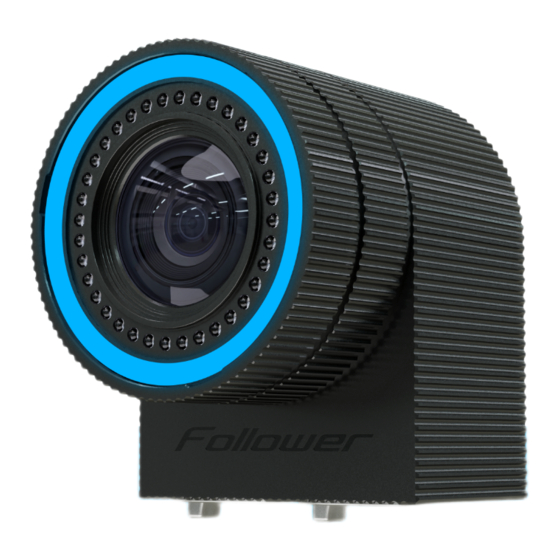
Page 11: Get Familiar With The Follower Witness Camera
10 W Figure 3.1 Follower witness camera consumption Visual RGB ring indicator TOP VIEW SIDE VIEW 96° 75° Figure 3.2 Follower witness camera Figure 3.3 Follower witness camera 96° FOV horizontally 75° FOV vertically © 2022 STYPE; ALL RIGHTS RESERVED. - Page 12 - RJ45 ethernet port to connect camera to the POE switch or to the OUT port of another witness camera* - RJ45 ethernet port to connect more than one camera in a daisy chain on one POE switch line* ----------------------------------------------------------------------------------------------------------------------------------------------- *more details in chapter 6.2 Daisy chain © 2022 STYPE; ALL RIGHTS RESERVED.
-
Page 13: Get Familiar With The Radio Transmitter
0.9 x 0.9 cm Power POE via CAT6 cable Power consumption Figure 4.1 Radio transmitter Figure 4.2 Radio transmitter port (PWR) Figure 4.3 Radio transmitter port (ANT) - Power supply RJ45 ethernet port - Antenna socket © 2022 STYPE; ALL RIGHTS RESERVED. -
Page 14: Get Familiar With The Spyder Module
Figure 5.3 Spyder module ports (PIPE and LENS) PIPE - Power supply sockets. - LED pipe sockets EXT LAN LENS - RJ45 ethernet port for data output. - 6 pin LEMO connector for connecting internal or external encoders. © 2022 STYPE; ALL RIGHTS RESERVED. -
Page 15: Mounting The Spyder
Figure 5.4 Mounting the Spyder module using the Universal mount EXTENSION BAR Seamlessly attaches itself directly on the camera body. FRONT VIEW SIDE VIEW Figure 5.5 Mounting the Spyder module using the Extension bar © 2022 STYPE; ALL RIGHTS RESERVED. -
Page 16: Lens Data Connection
0.6 gear module (Fujinon), or 0.8m gear module (Cine), an adjustable 0.8m gear module strap (available as part of the kit) needs to be fastened securely onto the required part(s) of the lens ring so that it will mesh with the Cine gears in the kit. © 2022 STYPE; ALL RIGHTS RESERVED. -
Page 17: Connectivity Diagram
POE SWITCH 802.3 AT/BT LENS CABLE CAT6 OR HIGHER BNC CABLE FOLLOWER MAIN SERVER POWER CABLE GENLCOK (BLACKBURST OR TRILEVEL) TIMECODE (LTC, BNC INPUT) POWER (110/220V), 400W MAX) RENDER ENGINE CLIENT NETWORK INTERNET (OPTIONAL) © 2022 STYPE; ALL RIGHTS RESERVED. -
Page 18: Mounting
Also, use a safety cable as a precautionary measure in case of magic clamp failure to prevent damage and injury. Figure 7.1 Follower witness camera mounting © 2022 STYPE; ALL RIGHTS RESERVED. -
Page 19: Daisy Chain
It is possible to connect up to eight Follower witness cameras in a chain where the first witness camera is connected directly to the switch and the others are connected in a chain. Follower 2.0 daisy chain possibilities: • Cameras with Part Number W300 - W399: up to 3 per chain •... -
Page 20: Object Tracking
When mounted, witness cameras should be directed to the middle of the tracked area. Figure 7.3 Follower witness cameras setup (object tracking) - TOP VIEW Figure 7.4 Follower witness cameras setup (object tracking) - SIDE VIEW © 2022 STYPE; ALL RIGHTS RESERVED. -
Page 21: Camera And Object Tracking
Ideally, vertically mounted witness cameras should see all of the LED beacons in their field of view. Figure 7.5 Follower witness cameras setup (object and camera tracking) - TOP VIEW Figure 7.6 Follower witness cameras setup (object and camera tracking) - SIDE VIEW © 2022 STYPE; ALL RIGHTS RESERVED. -
Page 22: Starting Up Follower
12. Studio Setup Setup Trackables >> more details in chapter 13. Setup Trackables Engine Network >> more details in chapter 14. Engine Network Operation mode >> more details in Figure 8.2 © 2022 STYPE; ALL RIGHTS RESERVED. -
Page 23: Main Screen Overview
Radio transmitter optional Follower witness camera connect all of them mandatory Spyder connect all of them optional Follower Network This process is done in the first chapter; >> more details in chapter 9.2 Initialization Phases © 2022 STYPE; ALL RIGHTS RESERVED. -
Page 24: Follower Network
- the way the specific part is sending the data in the network. It can be broadcast (B) or unicast (U). • - the way the specific part is receiving the data in the network. It can be broadcast (B) or unicast (U). • - firmware version of the part. © 2022 STYPE; ALL RIGHTS RESERVED. -
Page 25: Initialization Phases
(•) color represent devices that do not have the same Universe number as the master Follower computer. Figure 9.2 Discover and reset devices RESETS - reset the specific device to bootloader mode DISCOVER DEVICES - reset and discover all devices on the network © 2022 STYPE; ALL RIGHTS RESERVED. -
Page 26: Phase 2
All devices with whom communication has been established are shown in (•) color, while (•) PURPLE color represents devices with no communication after 2 seconds. (•) color represents devices that do not have the same Universe number as the system. © 2022 STYPE; ALL RIGHTS RESERVED. -
Page 27: Phase 3
All devices with whom communication has been established are shown in (•) color, while (•) color presents devices with no communication for two seconds. Figure 9.4 Devices syncing SYNCED - All devices are synced successefully © 2022 STYPE; ALL RIGHTS RESERVED. -
Page 28: Radio Devices
The frequency is selected by moving the sliding bar on the top of the screen and the DIP switch state cor- responding to that frequency is shown below. When operating frequency is chosen, all DIP switches on all receivers should be adjusted as shown below. © 2022 STYPE; ALL RIGHTS RESERVED. -
Page 29: Add Devices
10.2 Add devices Figure 10.2 Adding receivers Figure 10.3 Adding iPad tracker, Follower pen and Mini beacon © 2022 STYPE; ALL RIGHTS RESERVED. -
Page 30: Calibration
To turn the receiver on, use the ON/OFF switch. Figure 11.1 Calibration cross setup Figure 11.2 Calibration cross Figure 11.3 Calibration cross Figure 11.4 Calibration cross body with the in-build receiver pipe connector pipe LED © 2022 STYPE; ALL RIGHTS RESERVED. -
Page 31: Calibration Process
The goal is to have all cameras belonging to the same group. As the cameras learn their position, you can see the visual representation of their pairing process rectangle in the image below ) at the bottom section of the UI. Figure 11.7 Calibration process © 2022 STYPE; ALL RIGHTS RESERVED. -
Page 32: Studio Setup
12 STUDIO SETUP QUICK STUDIO SETUP REGULAR STUDIO In studio setup you can choose between 4 different setups: SETUP FINE TUNE STUDIO SETUP REDSPY STUDIO SETUP Figure 12.1 Studio setup menu © 2022 STYPE; ALL RIGHTS RESERVED. -
Page 33: Quick Studio Setup
QUICK SETUP REGULAR SETUP takes very little time. Compared to a it is less precise. Figure 12.1 Studio setup menu Figure 12.2 Quick Studio Setup Figure 12.3 Alignement of the calibration cross and studio layout © 2022 STYPE; ALL RIGHTS RESERVED. -
Page 34: Regular Studio Setup
Place the LED on the floor and click accuracy (particulary for large areas), more points can be added. Figure 12.5 Regular setup - SET Y AXIS SET Y AXIS. Raise the LED beacon above the floor plane, then click © 2022 STYPE; ALL RIGHTS RESERVED. - Page 35 Figure 12.7 Regular setup - SET ZERO PAN Move the LED beacon to a position away from the zero point in the direction of your Z axis. Click SET ZERO PAN to see the Z direction. © 2022 STYPE; ALL RIGHTS RESERVED.
-
Page 36: Fine Tune Studio Setup
12.3 Fine tune Studio Setup Here you can offset the position of the zero point (X, Y, Z) and orientation (pan, tilt, roll) of the studio axes. Figure 12.8 Fine tune Studio Setup © 2022 STYPE; ALL RIGHTS RESERVED. -
Page 37: Set Up Trackables
13.1 Spyder module Setup SPYDER SETUP is a 7 step process. Step 1 Select the Spyder you want to setup. Figure 13.1 Spyder module selection Step 2 Enter each beacon pipe length. Figure 13.2 Pipe length input © 2022 STYPE; ALL RIGHTS RESERVED. - Page 38 Upon starting the next rotation, the POSITIONS COLLECTED will increase. Repeat this process 15 times for each of the standard three axes (15 pan, 15 tilt and 15 roll rotations each). Figure 13.4 Spyder module calibration © 2022 STYPE; ALL RIGHTS RESERVED.
- Page 39 (as shown in the Figure 13.6), the X value should be 0. The X offset is positive if the Spyder is on the left, and negative if on the right (when looking into the camera lens). Figure 13.6 Spyder offsets input © 2022 STYPE; ALL RIGHTS RESERVED.
- Page 40 Choose your type of zoom and focus (inverted or normal), prime lens and hard stop if an option. Figure 13.7 Selecting encoders properties Step 8 You can select another Spyder module to setup if there is one or continue to the next chapter. Figure 13.8 Selecting another Spyder module to setup © 2022 STYPE; ALL RIGHTS RESERVED.
-
Page 41: Pipe Lenght And Zero Point
We measure the zero point of the Spyder module from the center of the Main Server when viewed from above, and the center of where the pipes meet the vertical center when viewed from the front or side. Figure 13.10 Measuring Spyder module zero point © 2022 STYPE; ALL RIGHTS RESERVED. -
Page 42: Create And Edit Trackables
In this step choose a device (or devices to combine) from the list, click the ports it will be using, then name the object. When finished, you may continue to the next step. Figure 13.11 Create and edit trackable objects © 2022 STYPE; ALL RIGHTS RESERVED. -
Page 43: Engine Network
Figure 14.1 Destination setup Once you have added the destinations select the engine where you want to send trackables. Also select the trackable and port. Ports start with 7000. Figure 14.2 Sending trackables to destinations © 2022 STYPE; ALL RIGHTS RESERVED. -
Page 44: Stype Data Recorder
15 STYPE DATA RECORDER Stype Data Recorder is a custom app for monitoring and recording of all Follower tracking data. Data are recorded in XML and FBX format. Figure 15.1 Stype Data Recorder The free version allows recording data for 10 seconds. You can download it from the QR code bellow. - Page 45 Port: 6301 on port 6301 on port 6301 This example is for the default subnet: 24 If you are on a network with a different subnet, the broadcast address might be different. © 2022 STYPE; ALL RIGHTS RESERVED.
- Page 46 Real-time XR / AR / VR tracking laboratory contact us at hi@stype.tv © 2022 STYPE; ALL RIGHTS RESERVED.
Need help?
Do you have a question about the Follower 2.0 and is the answer not in the manual?
Questions and answers