Table of Contents
Advertisement
Quick Links
Local Exhaust Ventilation Manual
& Log Book
(Principles, Installation, Maintenance and
Testing of Filtermist LEV Systems)
Company: ................................................................................
Unit Model No: .......................................................................
Unit Serial No: .......................................................................
Models
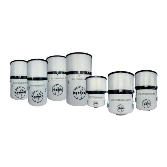
S200 : S400 : S800 : FX4002 : FX5002 : FX6002 : FX7002
Advertisement
Table of Contents

Related Manuals for Absolent Air Care Filtermist FX Series

Summary of Contents for Absolent Air Care Filtermist FX Series
- Page 1 Local Exhaust Ventilation Manual & Log Book (Principles, Installation, Maintenance and Testing of Filtermist LEV Systems) Company: ................Unit Model No: ............... Unit Serial No: ............... Models S200 : S400 : S800 : FX4002 : FX5002 : FX6002 : FX7002...
-
Page 2: General Information
General Information Definition “LEV (Local Exhaust Ventilation) is an engineering control system to reduce exposures to airborne contaminants such as dust, mist, fume, vapour, or gas in a workplace” (HSE 2011). Statutory Examination and Testing Every LEV system requires statutory thorough examination and testing by a competent person under the Control of Substances Hazardous to Health (COSHH) Regulations: 2002 (amended 2004). -
Page 3: Operation
General Information Filtermist as an LEV System Filtermist units are designed for the control of aerosol mists, namely those generated by machining operations that use either soluble or neat oil coolants. Other applications include component washing machines and EDM machines. Due to the aggressive nature of the fluid, it is recommended that only stainless-steel versions are used on component washing machine applications. -
Page 4: Mounting The Unit
Mounting the Unit Installation A Filtermist unit is normally sited either on (e.g. Fig.1) or close to the application, mounted on a stand (e.g. Fig.2) and therefore installation is straightforward requiring minimal ductwork. Filtermist units are light, require minimal floor space and can be installed in a wide variety of ways. A comprehensive library of existing installations is held by the company and can be used to demonstrate typical installations on most machine tools and applications. -
Page 5: Installation Information
Installation Information Safety Information Isolation from any power supply shall either be visible (visible break in the power supply circuits) or the isolation device is actuated to the off position and physically locked off. The unit must not be operated without the case fitted. At least seconds must be allowed for the inner drum to stop rotating before the case is removed. - Page 6 Installation Information Ducting runs should be as short as possible (e.g. Fig.3). U-bends should be avoided as these will encourage oil to collect, reduce airflow and become an area for potential leaks. Where U-bends are unavoidable, suitable drain- age points should be provided (e.g. Fig.4). •...
-
Page 7: Installation Methods
Installation Methods The following are typical installations and cover the majority of applications. For more advice on these or other installation methods please contact (01952 290500). Always try to position the extraction point as far as practically possible from the cutting area of the machine and so that mist is drawn away from the operator’s working area. - Page 8 Installation Methods Floor Stand Mount (S Series only.) e i l ) y l and secure. (3) Connect inlet of unit to extraction hole (4) Fit oil return tube and position tube to using suitable duct and adaptor (supplied drain oil back to machine enclosure, sump separately).
- Page 9 Installation Methods Floor Stand Mount (FX Series only.) (1) Remove 4 x insert screws in top of unit (2) Screw in 4 x eyebolts with nylon at 90° intervals. washers. s t l l i t inside of unit. (5) Position unit in stand and secure unit (6) Connect inlet of unit to extraction with bolts (supplied with unit).
-
Page 10: Airflow Indicator
F Monitor Airflow Indicator HSE guidelines recommend that Airflow Indicators are fitted to provide the machine operator with a visual indication that the extraction system is operating effectively. Please contact the Filtermist Sales Department (01952 290500) for details of this optional equipment. The F Monitor is a monitoring device that measures airflow and time to indicate when the filtermist unit needs servicing. -
Page 11: Electrical Connection
Electrical Connection Electrical Connection Filtermist FX series and S Series motors are wound for low & high voltage and operate on 50Hz & 60Hz as shown in the table below. A connection diagram can be found inside the motor terminal box. -
Page 12: Product Specifications
Product Specifications... -
Page 13: Maintenance Information
Maintenance Information Maintenance Filtermist can provide a full service and maintenance package to ensure that your Filtermist unit is working to its optimum efficiency. Please contact the office (Tel: 01952 290500 ) Should you wish to carry out maintenance yourself then always ensure you use genuine Filtermist spares. Guidelines on how to carry out maintenance are shown below. - Page 14 Maintenance Information Every 1000 Hours Running Time (use Filter Kit 4; see page 18 & 19) please refer to page 5 (1) Undo safety latch and clips. (2) Separate top and bottom of case. (3) Remove old seal. (4) Clean area where top and bottom (5) Remove old drum pads, clean inside (6) Fit new drum pads.
- Page 15 Maintenance Information (1) Undo safety latch and clips. (2) Separate top and bottom of case. (3) Remove old seal. (4) Clean area where top and bottom of case join & clean drain hole. (10) Withdraw motor from housing. (11) Remove old motor mounts and (12) Remove old silencer &...
- Page 16 Maintenance Information Every 2000 Hours Running Time (continued) please refer to page 5 (13) Re-fit motor to top of case. (14) IMPORTANT! Fit new motor (15) On the S Series, ensure bush, (15) Ensure bush (if your unit has mounting nuts & tighten (5Nm S Series shaft and drum hub are clean and free one), shaft and drum hub are clean and or 8Nm FX Series).
- Page 17 Maintenance Information Additional maintenance checks for all service intervals t fi blockage. (3) Check oil return hose for damage or (4) Check afterfilter (if fitted) and replace blockage. as necessary. Important Note In more arduous conditions e.g. grinding or cast iron machining; the units should be checked and cleaned on a more frequent basis, according to duty.
-
Page 18: Spares Information
Spares Information Item Item Item Item Motor S200 20-213-30-052 S400 20-213-30-161 S800 20-213-30-161 Drum S200 20-213-30-020 S400 20-213-30-021 S800 20-213-30-022 S200 20-206-10-000 Afterfilter (92% efficiency) S400 20-206-10-003 S800 20-206-10-003 High-Efficiency Afterfilter S200 No HE Afterfilter for the S200 (99.95% efficiency) S400 20-206-10-006 S800... - Page 19 Spares Information Item Item Item Item Motor FX4002 FX5002 FX6002/FX7002 Drum FX4002 20-213-30-015 FX5002 FX6002 20-213-30-013 FX7002 20-213-30-019 t l i 20-213-30-047 FX5002 20-213-30-048 For 1000 hour service FX6/7002 20-213-30-049 20-213-30-090 FX5002 20-213-30-092 For 2000 hour service FX6/7002 20-213-30-087...
-
Page 20: Troubleshooting
Troubleshooting Problem Possible Cause Action Unit vibrates or makes excessive noise Drum has solids build-up Clean the drum, ensuring all solids are removed from sides and base of vanes Damaged motor bearing and change filter pads Check motor bearing and replace motor if required Unit continues to vibrate Drum is out of balance... - Page 21 Local Exhaust Ventilation LOG BOOK...
-
Page 22: Daily Checks
General Information Schedule of Checks and Maintenance To ensure the continued performance of your Filtermist system, the following daily, weekly and monthly checks should be carried out. The forms included in this book should be used to record these checks, together with comments on any corrective action required. -
Page 23: Warranty
All new Filtermist oil mist Protect FREE filters come with a your people for longer Less potential Y E A R for downtime Added peace WARRANTY of mind No extra cost No extra co Precision Every single Filtermist unit undertakes rigorous Quality Assurance checks during the assembly process to ensure it meets our high engineered quality standards and reaches you in perfect condition. -
Page 24: Daily Log Sheet
Daily Log Sheet... - Page 25 Daily Log Sheet...
- Page 26 Daily Log Sheet...
- Page 27 Daily Log Sheet...
- Page 28 Daily Log Sheet...
-
Page 29: Weekly Log Sheet
Weekly Log Sheet... - Page 30 Weekly Log Sheet...
- Page 31 Weekly Log Sheet...
-
Page 32: Monthly Log Sheet
Monthly Log Sheet... -
Page 33: Maintenance Records
Maintenance Records Interim Service Full Service Interim Service Date Date Date Signed by Signed by Signed by 1000hrs 2000hrs 1000hrs Full Service Interim Service Full Service Date Date Date Signed by Signed by Signed by 2000hrs 1000hrs 2000hrs Unscheduled Maintenance/Repair Reason for Date Maintenance... -
Page 34: Ec Declaration Of Conformity
EC DECLARATION OF CONFORMITY Manufacturer’s Filtermist Limited Machinery covered by this declaration: name: Description: Filtermist Limited, Oil Mist Filter Telford 54 Business Park, Nedge Hill, To be fitted to machinery to extract Function: Full address: Telford, oil fumes TF3 3AL, England Type: S &... - Page 35 Filtermist Limited, Telford 54 Business Park, Nedge Hill, Telford, TF3 3AL, England Filtermist Limited, Telford 54 Business Park, Nedge Hill, Telford, TF3 3AL, England 1st January 2023...
- Page 36 Filtermist Limited Supplied by: Telford 54 Business Park Nedge Hill Telford Shropshire TF3 3AL England 20-218-10-033/Rev1 / 2023...
Need help?
Do you have a question about the Filtermist FX Series and is the answer not in the manual?
Questions and answers