
Related Manuals for Milltronics MultiRanger Plus PL-513


Summary of Contents for Milltronics MultiRanger Plus PL-513
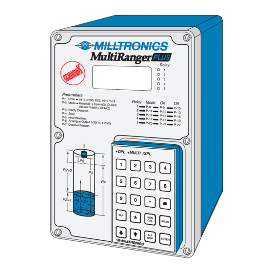
- Page 1 MultiRanger Plus Instruction Manual PL-513 January 1999 33455130 Technology based. Customer driven.
- Page 3 Table of Contents General Information About This Manual About the MultiRanger Plus Specifications MultiRanger Plus Programmer Transducer Temperature Sensor Current Output Isolator Cabling Installation Multiranger Plus Outline and Mounting Circuit Board Layout Recommendations Interconnection System Diagram Installing the Transducer Selecting Temperature Source Current Output Current Output Isolator Synchronization...
- Page 4 Common Display Messages Functional Transceiver Damping and Process Rate Temperature Compensation Sound Velocity Blanking Agitator Discrimination Relays General Function Alarm Pump Miscellaneous Analog Output Applications Simple Level Application Pump Control Applications Pump Run-On Pump Totalizer Application Volume Application Common Tank Shapes Custom Design Tanks Compensation Differential Level Application...
- Page 5 Parameter Description Parameters Troubleshooting General Oscilloscope Troubleshooting Guide Maintenance Maintenance Appendices Sound Velocities Glossary Alphabetical Parameter Listing PL-513...
- Page 6 PL-513...
- Page 7 GENERAL INFORMATION ABOUT THIS MANUAL First and foremost it is essential that this manual be read and understood before installation and start up of the MultiRanger Plus. "Applications" provides a general description of the common applications found in industry and illustrates them with examples. It is suggested that you refer to the sub-section which most suits your application.
- Page 8 PL-513...
- Page 9 SPECIFICATIONS MULTIRANGER PLUS » 100/115/200/230 V ac ±15%, 50/60 Hz, 15 VA Power: » optional: » 12 V dc model, 10 to 15 V dc, 15W » 24 V dc model, 18 to 30 V dc, 15W » fuse » FU2, Belling Lee, L754, 4000A HRC, ceramic type, 50mA, 250V »...
- Page 10 Approvals: » CE*, FM, CSA NRTL/C * EMC performance available upon request. Weight » 1.8 kg (4lb) PROGRAMMER Enclosure: » general purpose » 67 mm W x 100 mm H x 25mm D (2.6" W x 4" H x 1" D) »...
- Page 11 (3.2") (5.1") 240 mm (9.5") programmer 228 mm (9") Suitable location for conduit entrances. enclosure Milltronics recommends using a punch for making holes in enclosure. mounting holes customer mounting (accessed under lid screw 4.3 mm (0.17") dia. 4 places Non metallic enclosure does not provide grounding between conduit connections.
- Page 12 CIRCUIT BOARD LAYOUT daughter board optional isolator 10 to 15V dc operation 12 V dc model motherboard 18 to 30V dc operation 24 V dc model All field wiring must have insulation suitable for at least 250 V. Hazardous voltage present on transducer terminals during operation. dc terminals shall be supplied from an SELV source in accordance with IEC 1010-1 Annex H.
- Page 13 RECOMMENDATIONS 4.732" 3.291" drill for 3/4" 1.732" conduit hub (1 only) 1.708" 1.586" 1.043" drill for 1/2" conduit hubs (2 places) - mA output, N12, sync, temp sensor circuits (ter. 1-7), 14-20 Awg., copper wire, shielded - Trans circuit (ter. 8-9), Coaxial cable RG - 62 A/U - Relays, AC input circuit (ter.
- Page 14 INTERCONNECTION SYSTEM DIAGRAM Milltronics transducer,see MultiRanger Plus Specifications Milltronics TS-3, temperature sensor (optional) mA output customer device relay output customer alarm, pump or control device Maximum system capability. Not all components or their maximum quantity may be required. INSTALLING THE TRANSDUCER...
- Page 15 SELECTING TEMPERATURE SOURCE TS-3 or Program Integral Sensor board ‘B’ board ‘B’ CURRENT OUTPUT mA Output - GROUNDED (additional to basic wiring) Note : TB1-2 is internally connected to electrical ground TB1-26. to customer’s equipment maximum loading 350 Ω mA Output - FLOATING (additional to basic wiring) mA output wiring into floating input ONLY.
- Page 16 CURRENT OUTPUT ISOLATOR If the isolator has not been factory installed, mount it on the upper left hand corner of the motherboard using the two long machine screws provided. The input terminals of the isolator are then connected to the motherboard output terminals,TB-1, using twisted pair maximum 16 gauge wire.
- Page 17 To synchronize MultiRanger Plus’s and MultiRangers, interconnect the SYNC terminal TB1-4 of the MultiRanger Plus to the SYNC terminal TB1-9 of the MultiRanger. To synchronize more than 8 MultiRangers or MultiRangers with other Milltronics ultrasonic level detection models (e.g. MicroRanger, AirRanger, etc...) consult Milltronics or your distributor.
- Page 18 POWER CONNECTIONS AC Power VOLTAGE SELECT Switch shown in the ‘OFF’ position. Select appropriate voltage. 100 / 115 / 200 / 230 V 50 / 60 Hz 15 VA select voltage via switch The equipment must be protected by a 15 A fuse or circuit breaker in the building installation.
- Page 19 PROGRAMMER In order to program the MultiRanger Plus, a programmer ( which has a magnetic back plate ) must be placed into the front cover recess on the MultiRanger Plus. Be sure to keep it away from objects such as floppy disks that are susceptible to damage from magnetic fields.
- Page 20 PL-513...
- Page 21 START UP GENERAL The MultiRanger Plus has two modes of operation: Run and Program (Cal). When the unit is powered up, after installation procedures have been completed, it is factory set to start up in the run mode, to detect the distance from the transducer face to the target in meters.
- Page 22 PROGRAMMER KEYPAD All entries are made via the programmer keypad. Run Mode Press the associated key to view. H TOT • high total; P-2 = 4 or 5 (P-55) • PT 1; press to view level at DLD transducer #1 P-2 = 3 L TOT •...
- Page 23 Program Mode numeric entry decimal point entry negative entry clear display completes access into program mode enter run mode CA L press to make MEAS a measurement increments display to show the next parameter decrements display to show the preceeding parameter alternates display to show either the parameter number or DISP...
- Page 24 LEGEND Press the associated key on programmer: Display shown on MultiRanger Plus: Display appears for a short time: Programmer key: ENTER PARAMETER ENTRY Initial start up All entries are made via the programmer keypad. All programmers are interchangeable, thus any programmer can be used in conjunction with any MultiRanger Plus.
- Page 25 To set a parameter: access desired parameter e.g. P-20 display parameter value e.g. 0 DISP select new option e.g. 5 new value is entered and displayed e.g. 5 ENTER To reset a parameter to its factory value: e.g. reset P-20 display parameter value DISP display will go blank...
- Page 26 COMMON DISPLAY MESSAGES cable loss of echo » messages CAbL and LOE will alternately flash, indicating open or short circuited transducer connection have entered » appears after pressing program mode "RUN/CAL" key clear all parameters » P-99 - return factory setting overflow »...
- Page 27 FUNCTIONAL TRANSCEIVER The MultiRanger Plus transceiver will transmit via the transducer, a set of long and/or short pulses per measurement. The number and duration of the pulses is dependent upon P-88. A short pulse has a maximum measurement range of 2 m (6.6 ft) from the transducer face.
- Page 28 TEMPERATURE COMPENSATION In order to provide compensation for uniform temperature variances of the sound medium, temperature compensation is provided. Temperature compensation consists of on board circuitry in the MultiRanger Plus and the integal (transducer) temperature sensor. The integral temperature sensor uses the transducer’s wiring and input terminals (TB1 - 8/9) to interface with the on board circuitry.
- Page 29 P-63, velocity at 20 °C can be used to enter the known velocity at 20 °C of sound in a particular gas or vapour to view the resultant velocity of a sound velocity compensation, normalized to 20 °C. P-64, velocity at P-65, can be used to enter the known velocity of sound in a particular gas or vapour, or to view the resultant velocity of a sound velocity compensation, at the temperature of P-65.
- Page 30 measurement’s reliability and accuracy. If it is found that false echoes are appearing ahead of the blanking zone, P-87 should be reduced accordingly. Blanking is automatically corrected for sound velocity change where temperature and velocity compensation is used, keeping the blanking at the distance at which it was entered.
- Page 31 Function Alarm level : - in high alarm, the function goes on when the level rises to the ON setpoint and goes off when the level lowers to the OFF setpoint. In low alarm, the function goes on when the level lowers to the ON setpoint and goes off when the level rises to the OFF setpoint.
- Page 32 Pump level : - in pump down, the function goes on when the level rises to the ON setpoint and goes off when the level lowers to the OFF setpoint. In pump up, the function goes on when the level lowers to the ON setpoint and goes off when the level rises to the OFF setpoint.
- Page 33 Miscellaneous totalizer and samplers : - refer to Application Pump Totalizer and OCM . Relays are normally de-energized, contact closure is approximately 200 mSec duration. scanner : - this function is specific to relay 5 and the DLD mode of operation. The transducer hot is wired to the common terminal of the relay so that when switched, the transceiver may alternately access transducer #1and #2.
- Page 34 Simulation Parameters P-76 through P-78 can be used to simulate relay operation in the program mode. Pump relays will be held OFF during simulation, however their corresponding LED’s will respond. Remote totalizer and flow sampler relay operation do not apply to simulation.
- Page 35 RELAY PROGRAM CHART Relay 1 Relay 2 Relay 3 Relay 4 Relay 5 Fctn Setpoints Fctn Setpoints Fctn Setpoints Fctn Setpoints Fctn Setpoints Units Relay Function P-11 P-14 P-17 P-20 Alarm : Level P-10 P-12 P-13 P-15 P-16 P-18 P-19 P-20 P-21 In bounds...
- Page 36 ANALOG OUTPUT The MultiRanger Plus can be programmed to provide analog output (P-6) of 0 or 4 - 20 mA, proportional or inverse span. The 4 and 20 mA levels can be trimmed slightly via P-97 and P-98 respectively to compensate for any offset between the MultiRanger Plus and the customer’s equipment.
-
Page 37: Security
APPLICATIONS This section highlights the most common applications for which the MultiRanger Plus can be applied. Other applications not listed here may be similar to those listed or a combination thereof. ( e.g. monitoring piston position on a wood pulverizer is in essence a level application ) When programming, refer to the application which is most similar to yours. - Page 38 SIMPLE LEVEL APPLICATION PARAMETERS General Relays Pump Control Vol. & Disp. Totalizer Custom Filter Conversion units 1 function P-23 submers. P-34 tank P-40 primary P-51 OCM sim. P-60 full P-68 fill damp mode 1 on P-24 1 hrs. P-35 dim. A P-41 time P-52...
- Page 39 SIMPLE LEVEL APPLICATION The most common application of a Milltronics ultrasonic level measuring system is for simple level monitoring, whereby the material level or space measurement is displayed. This may or may not include alarms and mA output. When in the program mode, alarm relays hold their contact state. However, they will respond to measurements taken when "MEAS"...
- Page 40 PUMP CONTROL APPLICATION PARAMETERS General Relays Pump Control Vol. & Disp. Totalizer Custom Filter Conversion units 1 function P-23 submers. P-34 tank P-40 primary P-51 OCM sim. P-60 full P-68 fill damp mode 1 on P-24 1 hrs. P-35 dim. A P-41 time P-52...
- Page 41 PUMP CONTROL APPLICATIONS The basic difference between a simple level application and a pump control application is that the relays assigned to pump functions are normally in a de-energized state and are energized when pumping is required. The MultiRanger Plus can be programmed to control up to 5 pumps. Each may be configured in one of the following ways.
- Page 42 e.g. relays 1, 2 and 3 control three pumps by service ratio. It is required that pump 1 operate 60% of the time, pump 2 operate 10% of the time and pump 3 operate 30%of the time. » set the relay function : P-8, 11, 14 = dE : A9 »...
- Page 43 Pump Control Example The application is to control the level in a wet well 3 meters deep. It is required that : » the level is displayed in meters » to start/stop two constant speed pumps: start pump 1 at 1 m level start pump 2 at 2 m level stop both pumps at 0.5 m level »...
- Page 44 P-12 enter "2", relay 2 - pump ON P-13 enter " 5", relay 2 - pump OFF P-14 enter option "1", relay 3 - alarm function P-15 enter " 4", relay 3 - alarm ON P-16 enter " 45", relay 3 - alarm OFF deadband = 0.05 m, arbitrary setting P-23 enter option "1",...
- Page 45 Conditions of use : » Do not use run-on feature during pump-up operation as an overflow condition may occur. Set P-29 and 30 to 0. » Select the loss of echo default "dE" to protect pumps from cavitating in the event of loss of echo »...
- Page 46 PUMP TOTALIZER APPLICATION PARAMETERS General Relays Pump Control Vol. & Disp. Totalizer Custom Filter Conversion units 1 function P-23 submers. P-34 tank P-40 primary P-51 OCM sim. P-60 full P-68 fill damp mode 1 on P-24 1 hrs. P-35 dim. A P-41 time P-52...
- Page 47 PUMP TOTALIZER APPLICATION This type of application is an extension of the pump control application, accessed by setting P- 2 = 4. Unlike a pump application in which the mode of the measurement (P-2) can be of material or space, the pump volume totalizer mode is a measurement of the liquid volume pumped with reference to the material level.
- Page 48 high total low total e.g. P-54 P-55 8 digit total 1325 4679 If it is wished to momentarily view an alternate reading while in the run mode and ≠ P-39 0, press the desired programmer key ( ‘HEAD’ and ‘FLOW’ are not applicable to the pumped volume totalling ) e.g.
- Page 49 Pump Totalizer Example Further to the Pump Control Example it is required that the volume pumped be totalized. A daily flow total of 1,200 cubic meters is expected and a contact closure is required every 10 cu. m. The full level of the well is equal to 42 cu.m. The following parameters should be set.
- Page 50 VOLUME APPLICATION PARAMETERS General Relays Pump Control Vol. & Disp. Totalizer Custom Filter Conversion units 1 function P-23 submers. P-34 tank P-40 primary P-51 OCM sim. P-60 full P-68 fill damp mode 1 on P-24 1 hrs. P-35 dim. A P-41 time P-52...
- Page 51 VOLUME APPLICATION In addition to simple liquid level and pump applications, volume conversions can be included in the programming. Common Tank Shapes Volume conversion is provided for 8 common tank shapes, ( P-34 ). Dimensions are entered using P-4 and 36. Volume is displayed as 0-100% and may be converted to volume units using P-37.
- Page 52 P-35 enter ".75", tank dimension A P-36 enter "5", tank dimension L P-37 enter ".406", convert display, x.406 (automatically shows the levels in %). As 100% full = 40.6 cubic metres, a conversion factor of .406 must be entered. actual volume = conversion factor percentage P-68...
- Page 53 Custom Design Tanks Example ‘A’ The application is to measure the level of liquid in a custom designed tank. The tank manufacturer specifies the following level versus volume data. transducer 158.9 m @ 6 m 58.42 m @ 4 m 6.5 m 29.12 m @ 1m...
- Page 54 press display will show H - 3 - - - - (then) ENTER 3. 0 0 0 H - 4 - - - - (then) 4. 0 0 0 ENTER H - 5 - - - - (then) 6. 0 0 0 ENTER F - 5 - - - -...
- Page 55 Compensation In many volume applications, the ambient atmosphere is other than air or at a temperature other than 20 °C. Refer to Functional \ Temperature or \ Sound Velocity, for details on compensating for such circumstances. If it is noted that the MultiRanger Plus reading is consistently off by a constant amount as compared to the physical reading, this may be compensated for by P-62.
- Page 56 P-61 with the tank as empty as permissible and filled with its normal vapour and at its normal temperature press "MEAS". The MultiRanger Plus will take a measurement and display the level in the units selected, regardless that percent, volume or convert display are used.
- Page 57 PL-513...
- Page 58 DIFFERENTIAL LEVEL APPLICATION PARAMETERS General Relays Pump Control Vol. & Disp. Totalizer Custom Filter Conversion units 1 function P-23 submers. P-34 tank P-40 primary P-51 OCM sim. P-60 full P-68 fill damp mode 1 on P-24 1 hrs. P-35 dim. A P-41 time P-52...
- Page 59 DIFFERENTIAL LEVEL APPLICATION This type of application monitors the difference between two liquid levels, hence two transducers are required. The MultiRanger Plus monitors the two levels, calculates the difference and displays the differential as the reading. The following parameters should be left at their factory setting: »...
- Page 60 In order to use the MultiRanger Plus as a differential level detector TB-1 must be wired as in Installation \ Installing the Transducer and both transducers must be installed at the same level. A = transducers must be at the same elevation ( P-3 ). B = maximum differential ( Span, P-4 ) C = transducer should be mounted at least 0.3 m above the highest liquid level and 0.3 m away from the wall...
- Page 61 P-10 enter "6", relay 1 - reset this value can be arbitrarily set P-11 enter option "1", relay 2 - alarm function P-12 enter "20", relay 2 - alarm ON P-13 enter "19", relay 2 - alarm OFF P-20 enter option "14", relay 5 - scanner P-32 enter option "1",...
- Page 62 OPEN CHANNEL MEASUREMENT APPLICATION PARAMETERS General Relays Pump Control Vol. & Disp. Totalizer Custom Filter Conversion units 1 function P-23 submers. P-34 tank P-40 primary P-51 OCM sim. P-60 full P-68 fill damp mode 1 on P-24 1 hrs. P-35 dim.
- Page 63 OCM APPLICATION This application is specific to monitoring the flowrate in one of the four following categories of primary measuring devices. Refer to the respective drawings at the end of this section for weir and flume outlines and transducer location. Single Exponential, these are flumes and weirs that can be characterized by a single exponential term ( P-40 = 1 )
- Page 64 Flow readings are calculated by the MultiRanger Plus as a function of the head under the transducer, installed upstream from the primary measuring device ( P-40 ). The flows are then accumulated in the arbitrary volume units chosen per the time units of P-41 in an 8 digit totalizer.
- Page 65 In the program mode, the high and low totals can be viewed or preset to any value by P-54 and P-55 respectively. The flow readings ( high and low total ) may be scaled down by factors of 10 ( P-52 ) to slow down the totalizer’s rate of fill and its decimal point ( P-53 ) positioned for the resolution required.
- Page 66 An important consideration in OCM applications is that many primary measuring devices have the potential of running dry. In such cases, it must be insured that the range extension ( P-87 ) is sufficient so that the floor of the channel or of the converging section of the flume can be read.
- Page 67 select: enter option "3", units in feet enter option "5", enter "3", zero level distance to transducer enter "1.61", max head enter "1", near blanking distance, minimum allowable P-39 enter option "4", display flowrate in units per day P-40 enter option "1", primary measuring device - exponential P-41 enter option "4",...
- Page 68 select : enter "3.33" estimated empty distance to transducer enter option "2", 4 to 20 mA enter option "1", decimal location for head display max 1 digit after decimal enter option "1", relay 1 - alarm function enter option"1.8", relay 1 - alarm ON P-10 enter "1.5", relay 1 - alarm OFF...
- Page 69 Single Exponential, P-40 = 1 Weirs transducer 3 to 4 weir profile The transducer must be above the maximum head by at least the blanking value, P-5. Applicable Weir Profiles V - notch or sutro or cipolleti or suppressed triangular proportional trapezoidal rectangular...
- Page 70 Single Exponential P-40 = 1 ( cont’d ) FLUMES Parshall Flume plan transducer head front side » sized by throat width » set on solid foundation » general free flow equation is Q = K H where: Q = flow rate K = constant H = head x = exponent...
- Page 71 Single Exponential, P- 40 = 1 (cont’d) FLUMES (cont’d) Leopold Lagco (as manufactured by Leopold Co., Inc.) throat transducer plan diverging converging point of measurement head side front » designed to be installed directly into pipelines and manholes » Leopold Lagco may be classed as a rectangle Palmer-Bowlus flume »...
- Page 72 Single Exponential, P-40 = 1 ( cont’d ) FLUMES ( cont’d ) Cutthroat Flume » similar to Parshall flume except that the floor is flat bottomed and throat has no virtual length » refer to manufacturer’s specifications for flow equation and point of head plan measurement.
- Page 73 Palmer-Bowlus Flume, P-40 = 2 ( typically those manufactured by Warminster Fiberglass or Plasti-Fab ) plan transducer D / 2, point of measurement head side front » sized by pipe diameter, D. Enter value ( in units of P-1 ) into P-43. »...
-
Page 74: Inches
H Flumes, P-40 = 3 ( as developed by the U.S.Department of Agriculture, Soil Conservation Service ) transducer point of measurement plan front side » sized by max depth of flume, D. Enter value ( in units of P-1 ) into P-43. »... - Page 75 Other, P- 40 = 4 Where the primary measuring device does not fit one of the three other categories, P-40 may be programmed for one or two head versus flow characterizations: » P-40 = 4 : curved » P-40 = 5 : linear Select the characterization which most closely fits the flow characteristics of the primary measuring element.
- Page 76 select : enter option "3", units in feet advance to: enter option "5", enter "4", empty distance to transducer enter "3", span enter "1", near blanking distance P-39 enter option "4", display flowrate P-40 enter option "4", universal head vs flow press display will show H - 1...
- Page 77 press display will show 0.0 0 0 ENTER F - 2 - - - - (then) 2.1 5 6 ENTER F - 3 - - - - (then) 6.0 0 5 ENTER F - 10 - - - - (then) 5 1.1 2 ENTER F - 11...
- Page 78 APPLICATIONS WITH STANDPIPES In many solids and liquid applications, access to the vessel must be made via a standpipe. In such cases, Milltronics can provide flange mounted transducers that will readily mate to the standpipe. The maximum standpipe length that can be used without additional near blanking ( P-5 not greater than 0.3 m ) is 200 mm ( 8"...
-
Page 79: Table Of Contents
PARAMETER DESCRIPTION ( F ) indicates the parameter’s factory setting, where applicable. For reference only, factory set values may change with software revisions. ( V ) indicates that parameter can be viewed only, not entered. security This parameter can be used to lock out the programmer such that the content of parameters P-1 through P-99 can not be changed. - Page 80 span » distance between full ( high ) and empty ( low ) levels » maximum level differential if DLD ( P-2 = 3 ) is selected » maximum head if OCM ( P-2 = 5 ) is selected enter desired amount ( F = 10.00 m ) near blanking normally leave at factory setting.
- Page 81 P-11 relay 2 function Refer to Functional \ Relays. enter desired option ( F = 0 ) P-12 / 13 relay 2 - ON / OFF setpoints enter level in units as selected in P-1 or °C ( F = - - - - ) P-14 relay 3 function Refer to Functional \ Relays.
- Page 82 Parameters P-23 through P-33 are used specifically for pump applications. Refer to Applications \ Pump Control Applications. P-23 submersible transducer enter: 0 = normal ST- series transducer ( F ) 1 = submersible transducer P-24 relay 1 pump log * P-25 relay 2 pump log * P-26...
- Page 83 press display will show To view the service hours at the ‘P’ parameter e.g. 1,234 hours of service DISP ( F = 0.000 ) To view the number of starts at the ‘C’ parameter e.g. 321 pump starts ( F = 0 ) DISP To view the ratio setpoint at the ‘A’...
- Page 84 P-29 pump run-on interval the cyclical period in hours, in which a pump run-on duration may occur. The initial interval begins upon return to the run mode or resumption of power to the MultiRanger Plus. Subsequent intervals begin at the end of the previous interval. Intervals end after the time entered has expired or when the power or run mode is interrupted.
- Page 85 Parameters P-34 through P-39 are used for volume and display conversion. P-34 tank shape for volumetric conversion enter: = non volume - linear level measurement ( F ) = flat bottom = conic or pyramidic bottom = parabolic bottom = half sphere bottom = flat slope bottom = horizontal cylinder, flat ends...
- Page 86 = custom tank design * ( refer to Applications \ Volume Application ) This option is divided into two levels of subparameters: H - # where: H = level coordinate F - # F = volume coordinate # = breakpoint 1 to 11 Access is made by scrolling through the levels.
- Page 87 P-36 tank dimension ‘L’ horizontal length of tank shape excluding parabolic ends ( not required for other tank shapes ). enter " dimension L ", in units selected per P-1 ( F = 0.0 0 0 ) P-37 convert display parameter value is the factor by which the measurement is to be multiplied by before being displayed.
- Page 88 Parameters P-40 through P-50 used specifically for OCM applications. Refer to Applications. P-40 primary measuring device enter option: 1 = exponential ( F ) 2 = Palmer-Bowlus 3 = H-flume 4 = universal head vs flow - curve * 5 = universal head vs flow - linear * * these options are divided into 2 levels of subparameters: H - # where: H = level coordinate...
- Page 89 P-41 flow rate time units enter option: 1 = per second 2 = per minute 3 = per hour 4 = per day ( F ) P-42 OCM exponent exponent for primary measuring devices, P-40 = 1 where Q = K H Obtain from manufacturer’s specifications.
- Page 90 P-47 Auto zero this parameter allows automatic zero calibration for the empty distance to transducer parameter ( P-3 ) when the physical measurement is not obtainable. P-3 is the estimated empty distance to the transducer face with the transducer aimed at the proper portion of the crest in the open channel and at a height of at least 1 ft above maximum head.
- Page 91 P-51 OCM simulation press , display will show previous flow DISP enter head in units programmed, display will show head press , display will show corresponding flow ENTER Parameters P-52 through P-59 are used specifically for OCM and pump totalizer applications. Refer to Applications. P-52 totalizer display factor totalizer display of flow or volume pumped is factored by a power of...
- Page 92 P-55 high total the parameter will display the 4 highest digits of the 8 digit totalizer used in pump totalizer or OCM applications. The parameter will also allow the display to be reset to any value. ( F = 0000 ) P-56 remote totalizer contact control.
- Page 93 Parameters P-60 through P-67 are used to achieve specialized or custom calibration. P-60 full calibration this provides a measurement offset compensation on a full tank. A measurement offset might occur when parameters 3 and 4 do not exactly match the tank dimensions referenced for volume conversion.
- Page 94 P-62 measurement offset this displays the measurement offset: used in conjunction with a full tank calibration, P-60, or an offset value may be entered directly. The offset is added to the ultrasonic measurement such that its effect will be carried through the reading ( P-39, P-76 or ), mA output and relay setpoints.
- Page 95 Parameters in P-68 through P-75 are used to stabilize the reading. These are general purpose parameters, suitable for all applications. P-68 fill damping is the maximum rate at which the display reading and analog output will change under filling conditions. The damping rate is measured in P-1 units per minute and has a range of 0.001 to 9999.
- Page 96 this option is divided into two levels of subparameters: » S-71: time in seconds » D-71: distance in linear units as set in P-1 Access is made by scrolling through the levels. press display will show DISP ENTER Setting the subparameters is done the same way as with the ‘...
- Page 97 P-74 fail-safe mode in the event of a loss of echo, the MultiRanger Plus will flash " LOE " and go into one of the following fail-safe modes after the timer ( P-75 ) expires enter: 1 = high 2 = low 3 = hold last entry ( F ) P-75 fail-safe timer...
-
Page 98: Material Level
Pressing during simulation causes the apparent level to rise. Holding in , increases the rate of filling. Pressing causes the level to fall. Holding in , increases the rate of emptying. During simulation, relay LED’s, alarm relays and mA output are all enabled to allow full response of the MultiRanger Plus. - Page 99 Parameters P-79 through P-88 are used for echo processing and analysis. P-79 scope displays LCD Display window marker Curve - TVT Profile select any combination of scope displays 0 = scope display off ( display ‘ _ ’ ) ( F = _ _ _ _ ) 1 = scope display on ( display ‘...
- Page 100 P-81 confidence threshold for short measurement minimum echo confidence for echoes within 1 meter of transducer. If echoes are beyond 1 meter or have a confidence under the threshold level, the short measurement will be ignored and the long measurements will become valid. Enter threshold.
- Page 101 P-85 echo processing algorithms for long pulses ( for short pulses, a fixed algorithm is automatically selected ) enter: 1 = best echo of first and largest ( F ) 2 = first echo 3 = largest echo P-86 TVT curve enter: 1 = standard ( F ) 2 = flat...
- Page 102 Parameters P-89 through P-98 are used for testing. P-89 software revision number ( V ) P-90 memory test (V) ENTER press the display will show ‘ PASS ’ » memory test passed ‘ 1 ’ » RAM failure ‘ 2 ’ » EPROM failure ‘...
- Page 103 P-95 programmer test (V) press , then press each key from left to right starting with ENTER the top row. The display will acknowledge each key pressed: Display Display CA L MEAS DISP ENTER if any key is pushed out of sequence or malfunctions, the display will show ‘...
- Page 104 e.g. select P-97 press display will show meter will show DISP P-98 trim for 20 mA When this parameter is selected, the mA output goes to 20 mA. The display however, will show a typical value of 3490. The value can be increased or decreased by pressing respectively or by entering a value.
- Page 105 TROUBLESHOOTING GENERAL There are a few adjustments for echo processing and they should be used judiciously. Transducer location and aiming are the most important factors affecting the reliability of the MultiRanger Plus . Location and aiming of the transducer may be optimized by pressing to view the confidence level while in the RUN mode.
- Page 106 The processed echo display ( P-79 ) can be made to show not only the processed echo profile, but also the: • echo marker • window • TVT curve or auxiliary window Typical scope settings for viewing the processed echo are: •...
- Page 107 TROUBLESHOOTING GUIDE The following is a list of operating symptoms, their probable causes and the actions to resolve them. SYMPTOM CAUSE ACTION Loss of Echo ( LOE ) display will flash open circuit check transducer wiring * CAbL / LOE, neon L1 will flash but no pulsing is felt on the transducer face defective transducer...
- Page 108 SYMPTOM CAUSE ACTION . . . continued transducer location re-locate or re-aim or aiming : transducer for maximum - poor installation echo confidence, P-80 * - moved by material or vibration - flanging not level transducer malfunction check P-65, 66 & 67 - temperature too high or inspect - physical damage...
- Page 109 SYMPTOM CAUSE ACTION MultiRanger Plus will not programmer improperly refer to installation respond to programmer positioned infrared window clean obstructed programmer battery low test programmer P-95 Reading erratic echo confidence weak refer to P-85, 86 87 & 88 liquid surface agitated increase damping, P-68 &...
- Page 110 PL-513...
- Page 111 MAINTENANCE The MultiRanger Plus requires no maintenance, however a program of periodic checks would be beneficial. The enclosure and circuit boards should be cleaned if necessary, but only when the power is disconnected at the main breaker and using a vacuum cleaner and a clean, dry paint brush.
- Page 112 PL-513...
- Page 113 SOUND VELOCITIES GASES (0 °C) m/sec ft/sec air, dry 1086 ammonia 1362 argon 1010 carbon dioxide carbon monoxide 1109 chlorine deuterium 2920 ethane (10 °C) 1010 ethylene 1040 helium 3166 hydrogen 1284 4213 hydrogen bromide hydrogen chloride hydrogen iodide hydrogen sulfide illuminating (coal gas) 1486 methane...
- Page 114 GLOSSARY Aeration: air gap between nappe and weir. Beam angle: angle between the opposing one-half power limits (–3 dB) of the sound beam Blanking: zone in which received echoes are ignored. Crest: the edge ( sharp-crested weir ) or surface ( broad crested weir ) over which the flow passes.
- Page 115 Stilling well: a well separate from but adjacent to the primary measuring device and interconnected by a small duct to provide an ideal point of head measurement. Subcritical flow: same as submerged flow. Submerged flow: when the downstream level rises or the discharge flow is so slow that it impedes the free flow of liquid through the primary measuring device.
- Page 116 ALPHABETICAL PARAMETER LISTING PARAMETER PARAMETER agitator discrimination P-73 pump 5, hours P-28 air temperature P-65 pump, run-on, duration P-30 air temperature, maximum P-66 pump, run-on, interval P-29 air temperature, minimum P-67 range extension P-87 algorithms P-85 rate display P-70 analog output rate filter P-71 analog output, DLD...
Need help?
Do you have a question about the MultiRanger Plus PL-513 and is the answer not in the manual?
Questions and answers