
Related Manuals for Hobart Welding Products STICKMATE 235 AC


Summary of Contents for Hobart Welding Products STICKMATE 235 AC
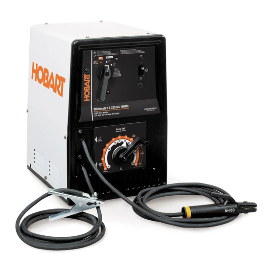
- Page 1 OM-254 339-A 2011−08 Processes Stick (SMAW) Welding Description AC/DC Models: AC Models: Arc Welding Power Source STICKMATE WELDING POWER SOURCES 205 AC, 235 AC And 235/160 AC/DC File: Stick (SMAW)
- Page 2 From Hobart to You Thank you and congratulations on choosing Hobart. Now you can get the job done and get it done right. We know you don’t have time to do it any other way. This Owner’s Manual is designed to help you get the most out of your Hobart products.
-
Page 3: Table Of Contents
TABLE OF CONTENTS SECTION 1 − SAFETY PRECAUTIONS - READ BEFORE USING ....... . . 1-1. -
Page 5: Section 1 − Safety Precautions - Read Before Using
SECTION 1 − SAFETY PRECAUTIONS - READ BEFORE USING som 2011−01 Protect yourself and others from injury — read and follow these precautions. 1-1. Symbol Usage DANGER! − Indicates a hazardous situation which, if Indicates special instructions. not avoided, will result in death or serious injury. The possible hazards are shown in the adjoining symbols or explained in the text. - Page 6 D Remove stick electrode from holder or cut off welding wire at FUMES AND GASES can be hazardous. contact tip when not in use. D Wear oil-free protective garments such as leather gloves, heavy Welding produces fumes and gases. Breathing shirt, cuffless trousers, high shoes, and a cap.
-
Page 7: Additional Symbols For Installation, Operation, And Maintenance
1-3. Additional Symbols For Installation, Operation, And Maintenance FIRE OR EXPLOSION hazard. MOVING PARTS can injure. D Do not install or place unit on, over, or near D Keep away from moving parts such as fans. combustible surfaces. D Keep all doors, panels, covers, and guards D Do not install unit near flammables. -
Page 8: California Proposition 65 Warnings
1-4. California Proposition 65 Warnings For Gasoline Engines: Welding or cutting equipment produces fumes or gases which contain chemicals known to the State of California to Engine exhaust contains chemicals known to the State of cause birth defects and, in some cases, cancer. (California California to cause cancer, birth defects, or other reproduc- Health &... -
Page 9: Section 2 − Consignes De Sécurité − Lire Avant Utilisation
SECTION 2 − CONSIGNES DE SÉCURITÉ − LIRE AVANT UTILISATION fre_som_2011−01 Se protéger et protéger les autres contre le risque de blessure — lire et respecter ces consignes. 2-1. Symboles utilisés DANGER! − Indique une situation dangereuse qui si on Indique des instructions spécifiques. - Page 10 Il reste une TENSION DC NON NÉGLIGEABLE dans LE SOUDAGE peut provoquer un les sources de soudage onduleur UNE FOIS incendie ou une explosion. l’alimentation coupée. Le soudage effectué sur des conteneurs fermés tels D Arrêter les convertisseurs, débrancher le courant électrique et que des réservoirs, tambours ou des conduites peut décharger les condensateurs d’alimentation selon les instructions provoquer leur éclatement.
-
Page 11: Dangers Supplémentaires En Relation Avec L'installation, Le Fonctionnement Et La Maintenance
ACCUMULATIONS LES BOUTEILLES peuvent exploser risquent de provoquer des blessures si elles sont endommagées. ou même la mort. Les bouteilles de gaz comprimé contiennent du gaz sous haute pression. Si une bouteille est D Fermer l’alimentation du gaz comprimé en cas endommagée, elle peut exploser. -
Page 12: Proposition Californienne 65 Avertissements
Les PIÈCES MOBILES peuvent RAYONNEMENT HAUTE causer des blessures. FRÉQUENCE (H.F.) risque provoquer des interférences. D Ne pas s’approcher des organes mobiles. D Ne pas s’approcher des points de coincement D Le rayonnement haute fréquence (H.F.) peut tels que des rouleaux de commande. provoquer des interférences avec les équi- pements de radio−navigation et de com- munication, les services de sécurité... -
Page 13: Principales Normes De Sécurité
2-5. Principales normes de sécurité Safety in Welding, Cutting, and Allied Processes, ANSI Standard Z49.1, 25 West 43rd Street, New York, NY 10036 (téléphone : 212-642-4900, de Global Engineering Documents (téléphone : 1-877-413-5184, site site Internet : www.ansi.org). Internet : www.global.ihs.com). Standard for Fire Prevention During Welding, Cutting, and Other Hot Safe Practices for the Preparation of Containers and Piping for Welding Work, NFPA Standard 51B, de National Fire Protection Association,... - Page 14 OM-254 339 Page 10...
-
Page 15: Section 3 − Definitions
A complete Parts List is available at www.HobartWelders.com SECTION 3 − DEFINITIONS 3-1. Symbols And Definitions Do Not Switch Amperes Single Phase Input Under Load Output Hertz Alternating Electrode Positive Electrode Negative Direct Current Current Welding Arc Volts Work Electrode Single Phase Single Phase Transformer AC &... -
Page 16: Section 4 − Installation
A complete Parts List is available at www.HobartWelders.com SECTION 4 − INSTALLATION 4-1. Specifications A. AC/DC Models (LX) Amperes Input at Rated Load Maximum Output 50 Or 60 Hz, Open- Rated Welding Amperage Mode Weight Single-Phase Circuit Output Range Voltage 230 V 225 A @ 25 Volts AC, Low: 30 −... -
Page 17: Duty Cycle Charts
A complete Parts List is available at www.HobartWelders.com 4-2. Duty Cycle Charts A. For AC/DC Models (LX) Duty Cycle is percentage of 10 minutes that unit can weld at rated load without overheating. NOTICE − 20% Duty Cycle at 225 Amperes. - Page 18 A complete Parts List is available at www.HobartWelders.com C. For 205 AC Model Duty Cycle is percentage of 10 minutes that unit can weld at rated load without overheating. NOTICE − 20% Duty Cycle at 165 Amperes. Exceeding duty cycle can dam- age unit and void warranty.
-
Page 19: Volt-Ampere Curves
A complete Parts List is available at www.HobartWelders.com 4-3. Volt-Ampere Curves A. For AC/DC Models (LX) The volt-ampere curves show the minimum and maximum voltage and amperage output capabilities. Curves of other settings fall be- tween the curves shown. For 235/160A Models AC Amperes DC Amperes 193 509 / 193 510... - Page 20 A complete Parts List is available at www.HobartWelders.com B. For AC Models (LX) The volt-ampere curves show the For 235A Models minimum and maximum voltage and amperage output capabilities. Curves of other settings fall be- A=LOW RANGE tween the curves shown. B=HIGH RANGE AC Amperes 193 508...
-
Page 21: Serial Number And Rating Label Location
A complete Parts List is available at www.HobartWelders.com 4-4. Serial Number And Rating Label Location The serial number and rating information for this product is located on back. Use rating label to determine input power requirements and/or rated output. For future reference, write serial number in space provided on back cover of this manual. 4-5. -
Page 22: Installing Electrode Holder And Work Clamp
A complete Parts List is available at www.HobartWelders.com 4-6. Installing Electrode Holder And Work Clamp Turn Off unit and disconnect input power before installing electrode holder or work clamp. Removing Barrel From Electrode Holder Electrode Holder Barrel Access Hole Set Screw Loosen set screw through access hole and slide barrel away from electrode holder. -
Page 23: Weld Output Cables
A complete Parts List is available at www.HobartWelders.com 4-7. Weld Output Cables For weld output cable replacements or extensions, contact your Factory Authorized Service Agent. 4-8. Electrical Service Guide Failure to follow these electrical service guide recommendations could create an electric shock or fire hazard. These recommenda- tions are for a dedicated branch circuit sized for the rated output and duty cycle of the welding power source. -
Page 24: Connecting Input Power
A complete Parts List is available at www.HobartWelders.com 4-9. Connecting Input Power Installation must meet National and Local Codes − have only qualified persons make this installation. Disconnect and lockout/tagout input power before installing =GND/PE Earth Ground receptacle. See rating label on unit and check in- put voltage available at site. -
Page 25: Section 5 − Operation
A complete Parts List is available at www.HobartWelders.com SECTION 5 − OPERATION 5-1. Controls A. Controls For AC/DC Models (LX) Amperage Adjustment Control Power Switch Mode Switch For DC Weld Output Use mode switch to select polarity of DC output, Electrode Posi- tive/DCEP (+),or Electrode Nega- tive/DCEN (−). - Page 26 A complete Parts List is available at www.HobartWelders.com B. Controls For AC Models (LX) Amperage Adjustment Control Power Switch Mode Switch Use mode switch to select AC low range or high range output. Ref. 254 304-A / 802 105-D OM-254 339 Page 22...
- Page 27 A complete Parts List is available at www.HobartWelders.com C. Controls For 205 AC Model Amperage Adjustment Control Power Switch Ref. 254 303-A / 803 583-B OM-254 339 Page 23...
-
Page 28: Section 6 − Maintenance & Troubleshooting
A complete Parts List is available at www.HobartWelders.com SECTION 6 − MAINTENANCE & TROUBLESHOOTING 6-1. Routine Maintenance Disconnect power Maintain more often before maintaining. during severe conditions. n = Check Z = Change ~ = Clean l = Replace Reference * To be done by Factory Authorized Service Agent Every Months... -
Page 29: Reinstalling Amperage Adjustment Indicator
A complete Parts List is available at www.HobartWelders.com 6-3. Reinstalling Amperage Adjustment Indicator A. For LX Models Turn Off welding power source and disconnect input power. Wrapper Remove wrapper from unit. Crank Handle Shunt Shaft Transformer And Shunt (Located Inside Unit) Insert crank handle onto shunt shaft protruding through front panel and turn crank handle to adjust... - Page 30 A complete Parts List is available at www.HobartWelders.com B. For 205 AC Model Turn Off welding power source and disconnect input power. Wrapper Remove wrapper from unit. Crank Handle Shunt Shaft Transformer And Shunt (Located Inside Unit) Insert crank handle onto shunt shaft protruding through front panel and turn crank handle to adjust shunt to 2-5/8 in.
-
Page 31: Troubleshooting
A complete Parts List is available at www.HobartWelders.com 6-4. Troubleshooting Trouble Remedy No weld output; fan does not run. Be sure line disconnect switch is in On position (see Section 4-9). Check and replace line fuses if open. Reset breakers if necessary (see Section 4-9). Fan does not run;... -
Page 32: Section 7 − Electrical Diagrams
SECTION 7 − ELECTRICAL DIAGRAMS 191 364 Figure 7-1. Circuit Diagram For AC/DC (230 Volts) Models VOLT ONLY PLG1 AC HIGH AC LOW WORK ELECTRODE 191 362 Figure 7-2. Circuit Diagram For AC (230 Volts) Models OM-254 339 Page 28... - Page 33 215 254-A Figure 7-3. Circuit Diagram For 205 AC Model OM-950 Page 29 Return To Table Of Contents...
-
Page 34: Section 8 − Stick Welding (Smaw) Guidelines
SECTION 8 − STICK WELDING (SMAW) GUIDELINES 8-1. Stick Welding Procedure Weld current starts when electrode touches work- piece. Equipment Needed: Tools Needed: Weld current can damage electronic parts in vehicles. Disconnect both battery cables before welding on a vehicle. Place work clamp as close to the weld as possible. - Page 35 8-2. Electrode and Amperage Selection Chart 6010 DEEP 3/32 MIN. PREP, ROUGH HIGH SPATTER 6011 DEEP 6010 5/32 & 6013 EP,EN GENERAL 3/16 6011 7/32 SMOOTH, EASY, 7014 EP,EN FAST 1/16 LOW HYDROGEN, 7018 5/64 STRONG 3/32 FLAT SMOOTH, EASY, 7024 EP,EN HORIZ...
- Page 36 8-4. Positioning Electrode Holder End View Of Work Angle Side View Of Electrode Angle ° ° ° ° Groove Welds ° ° ° ° Fillet Welds S-0060 8-5. Poor Weld Bead Characteristics Large Spatter Deposits Rough, Uneven Bead Slight Crater During Welding Bad Overlap Poor Penetration S-0053-A...
- Page 37 8-7. Conditions That Affect Weld Bead Shape Weld bead shape is affected electrode angle, length, travel speed, and thick- ness of base metal. Correct Angle ° - ° Angle Too Large Angle Too Small Electrode Angle Drag Spatter Arc Length Normal Too Long Too Short...
- Page 38 8-9. Groove (Butt) Joints Tack Welds Prevent edges of joint from draw- ing together ahead of electrode by tack welding the materials in posi- tion before final weld. Square Groove Weld Good for materials up to 3/16 in. (5 mm) thick. Single V-Groove Weld Good for materials 3/16 −...
- Page 39 8-12. Weld Test Vise Weld Joint Hammer Strike weld joint in direction shown. A good weld bends over but does not break. 2 To 3 in. (51-76 mm) 2 To 3 in. (51-76 mm) 1/4 in. (6.4 mm) S-0057-B 8-13. Troubleshooting Porosity −...
- Page 40 Lack Of Penetration − shallow fusion between weld metal and base metal. Lack of Penetration Good Penetration Possible Causes Corrective Actions Improper joint preparation. Material too thick. Joint preparation and design must provide access to bottom of groove. Improper weld technique. Keep arc on leading edge of weld puddle.
- Page 41 Notes Work like a Pro! Pros weld and cut safely. Read the safety rules at the beginning of this manual.
- Page 42 Notes MATERIAL THICKNESS REFERENCE CHART 24 Gauge (.025 in.) 22 Gauge (.031 in.) 20 Gauge (.037 in.) 18 Gauge (.050 in.) 16 Gauge (.063 in.) 14 Gauge (.078 in.) 1/8 in. (.125 in.) 3/16 in. (.188 in.) 1/4 in. (.25 in.) 5/16 in.
- Page 43 Effective January 1, 2011 5/3/1 WARRANTY applies to all Hobart welding equipment, plasma cutters and spot welders with a Warranty Questions? serial number preface of MB or newer. Call This limited warranty supersedes all previous Hobart warranties and is exclusive with 1-800-332-3281 no other guarantees or warranties expressed or implied.
- Page 44 Contact the Delivering Carrier to: File a claim for loss or damage during shipment. For assistance in filing or settling claims, contact your distributor and/or equipment manufacturer’s Transportation Department. © ORIGINAL INSTRUCTIONS − PRINTED IN USA 2011 Hobart Welding Products. 2011−01...
Need help?
Do you have a question about the STICKMATE 235 AC and is the answer not in the manual?
Questions and answers