
Related Manuals for Allfett ALL-1


Summary of Contents for Allfett ALL-1
- Page 1 ALL-1 Standard ALL-1 With integrated controller ELECTRICAL GREASE PUMPS INTRODUCTION AND USER MANUAL VERSION 2.00 THE PHYSICAL LIFE DETERMINED BY MINISTRY OF INDUSTRY AND TRADE OF TURKEY IS 10 YEARS.
-
Page 2: Introduction
ALLFETT is among the few companies whose products meet the exact technical and quality standards for a correct central lubrication. We present our high quality and advanced product design concept to our worldwide costumers through our strong brand. -
Page 3: Table Of Contents
PUMP ELEMENT DESCRIPTION PAGE 7 LUBRICANT INFORMATION PAGE 8 - 9 ELECTRICAL CONNECTION of ALL-1 Standard PAGE 10 ELECTRICAL CONNECTION of ALL-1 with Integrated contol PAGE 11 INTEGRATED CONTROL CARD DESCRIPTION PAGE 12 INTEGRATED CONTROL CARD PROGRAMMING INSTRUCTIONS PAGE 13... -
Page 4: Product Description And General Specifications
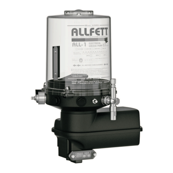
The pump reservoir is manufactured from transparent polycarbonate to allow user easily check the level of grease. In case the pump is installed so that operator cannot see the level of grease the ALLFETT low level sensor can be used to follow the level of grease. Top filling application is possible with different filling covers, with or without lock. -
Page 5: Product Dimensions
PRODUCT DIMENSIONS Technical drawings below represents the ALL-1 pump models which has different reservoir capacities. Dimension unit is milimeter. 4 Liters 3.3 Liters 1.5 Liters 10 Liters 8 Liters 6 Liters 120 mm 12 Liters Ø9.1 Pump body assembly... -
Page 6: Product Components
PRODUCT COMPONENTS Technical drawings below represents the ALL-1 pump’s standard model and ALL-1 Pump with integrated control model. Optional specifications described seperately. ALL-1 with integrated control ALL-1 Standard Level indicator socket (Optional) Sieve Level indicator (Optional) Agitator Reservoir monobloc type... -
Page 7: Function
FUNCTIONAL DESCRIPTION Along with “ DC ” voltage electrical energy connected to ALL-1 pump filled with grease ; Electrical motor start to operate and agitator inside reservoir rotates clockwise. Spring returned pump element piston vacuums the lubricant inside reservoir. Rotational movement of the eccentric pushes pump element piston so that the lubricant vacoomed before is sended to pump element outlet with high pressure. -
Page 8: Pump Element Description
ALL-1 grease pumps are available in several displacement volumes. These volumes can be created with pump elements which are optionally offered. 1 to 6 Pump elements can be applied onto ALL-1 pump body to take grease out. Even though single pump element can be used as outlet, multiple pump elements can be bridged as single outlet to get more displacement. -
Page 9: Lubricant Information
Lubricant type - GREASE NLGI classes can be used with ALL-1 pumps are described below. Because of the flow characteristics of grease the NLGI class range should be changed at different weather conditions and also temperature differencies. - Page 10 LUBRICATION INFORMATION Grease penetration properties is variable at different environment temperatures.The environmental temperature around lubrication lines must be concidered for choosing the correct grease. Grease properties should be appropriate that environmental temperatures. Changing NLGI classes at different temperatures is important to correct lubrication.
-
Page 11: Electrical Connection Of All-1 Standard
Any maintenance on ALL-1 pumps under electrical voltage could lead to personal injury. Disconnect all electrical power before any maintenance . If ALL-1 DC pump will be used with ALLFETT EK-9 external control card, electrical lines must be connected properly as described in schema below. -
Page 12: Electrical Connection Of All-1 With Integrated Contol
ELECTRICAL CONNECTIONS of ALL-1 INTEGRATED CONTROL CARD Pumps have an electric driven motor. Electrical lines must be connected properly as described in schema below. Electrical socket is placed under control card box shown below. Integrated control card S1 - Standard electrical connection... -
Page 13: Integrated Control Card Description
ADDITIONAL CYCLE : Using to lubricate only one time except the programmed working time. And also using to change numbers while programming. INTEGRATED CONROL CARD COMPONENTS Integrated control card is optional. Not presented onto standard ALL-1 pumps. Control panel cover Motor connection cables screws... -
Page 14: Integrated Control Card Programming Instructions
INTEGRATED CONTROL CARD PROGRAMMING INSTRUCTIONS SERVICE and ADDITIONAL CYCLE buttons, where placed onto control card panel, are used for programming control card. 1. Press SERVICE Button twice to enter program mode. After entering program mode first digit on program display and green led start to flash. Working time period will be set first. -
Page 15: Rules To Comply While Using And Warranty Conditions
RULES TO COMPLY WHILE USING AND WARRANTY CONDITIONS Damages occur while additional transports after delivering the goods from ALLFETT to the customer DISQUALIFIES THE WARANTY. Pumps are produced to lubrication purpose only and are not convenient to work more than 2 hours continuously. - Page 16 Damages on pump and on the system coming from that reason DISQUALIFIES THE WARANTY. 18. Using ALL-1 pumps with integrated control card models, high frequency wireless cominication devices 1 meter distance from the pump may couse malfunction. Damages or faults occur from this reason DISQUALIFIES THE WARANTY.
-
Page 17: Pump Maintenance
Fill the reservoir according to items 10, 11, 12, 13, 14, 15 and 16 in RULES TO COMPLY WHILE USING AND WARRANTY CONDITIONS. If ALLFETT control card is connected the system ; Electronic control card may be in waiting period. Wait until working time starts. -
Page 18: Pump Element Maintenance
Blockage must be identified and fixed. Pump body Pump element outlet Security valve body Pump element body Grease suction hole Piston spring Piston Security valve discharge ALL-1 pump body is suitable for 1 and up to 6 pump elements. PAGE... -
Page 19: Order Information
ALL-1 Standard pump - 24 V DC - 12 Lt. 20 24 12 A1 ALL-1 Pump with integrated control - 12 V DC - 1.5 Lt. 20 12 15 EC ALL-1 Pump with integrated control - 12 V DC - 3.3 Lt. -
Page 20: Warranty
Industrial and Commerce, The general Administration of Protection of Consumer Right and Competition, in accordance with the law numbered 4077 . PRODUCER COMPANY NAME : ALLFETT Mekanik ve Elektronik Sistemler San. ve Tic. Ltd. Þti. CENTRAL ADRESS Yeni Eyup Bulvari, Topcular Cad. Set Ustu, No:1 Demirkapý- Rami / Ýstanbul... -
Page 21: Warranty Conditions
WARRANTY CONDITIONS The warranty period is two years from the date of delivery. The product including all its components is under the warranty of our company. In case of defects within the warranty period the period spent in repairing is added to the warranty period. - Page 22 DANGEROUS OR HARMFUL CONDITIONS TO ENVIRONMENTAL AND HUMAN HEALTH DURING USE All ALLFETT systems are producing according to relevant provisions of security regulations. There is no risk for environmental and human health during use. TRANSPORT AND STORAGE There are no restrictions on transportation by land, air and sea. In general, products should be stored in a dry and dust-free environment.
- Page 23 NOTES PAGE...
Need help?
Do you have a question about the ALL-1 and is the answer not in the manual?
Questions and answers