
Related Manuals for Jack & June Haven Playset


Summary of Contents for Jack & June Haven Playset
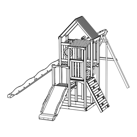
- Page 1 Haven Playset (JJ-Haven) 2L-7963-00 817 Maxwell Avenue • Evansville, IN 47711 • 1-800-GO-SWING • www.escaladesports.com • ©2021 Escalade Sports...
- Page 2 I N T R O D U C T I O N Welcome to our family of ready-to-build backyard play equipment. Jack & June playsets are designed with ease of assembly in mind and we provide these step-by-step installation instructions. After reading the information below, locate your structure site and carefully unpack parts.
- Page 3 S A F E T Y I N S T R U C T I O N S Teach Children: • Not to walk close to, in front of, behind, or between • Not to stand in the swing seats. moving items.
- Page 4 STANDARD HARDWARES LIST 3/8” x 7” HEX BOLT PG-HW-B012 3/8” x 6-1/2” HEX BOLT PG-HW-B001 3/8”-16 x 1/2” T-NUT 3/8” NYLON LOCKNUT PG-HW-N002 PG-HW-N001 (14) 3/8” x 5-3/4” HEX BOLT PG-HW-B024 (10) #10 FLAT WASHER 3/8” FLAT WASHER PG-HW-W001 PG-HW-W004 3/8”...
- Page 5 STANDARD HARDWARE LIST 3/8” x 5” HEX LAG SCREW PG-HW-L010 5/16” x 3.5” HEX LAG SCREW 5/16” x 2.5” HEX LAG SCREW PG-HW-L020 PG-HW-L003 (16) (48) 1/4” x 4.5” HEX LAG SCREW 5/16” x 1.5” HEX LAG SCREW PG-HW-L002 PG-HW-L021 (30) (30) 5/16”...
- Page 6 STANDARD HARDWARE LIST #10 x 1.25” ROUND HEAD SCREW #10 x 1” ROUND HEAD SCREW PG-HW-S002 PG-HW-S001 (36) #8 x 2” FLAT HEAD WOOD SCREW #8 x 1.5” FLAT HEAD WOOD SCREW PG-HW-S004 PG-HW-S003 (136) (106) #8 x 3” FLAT HEAD WOOD SCREW #8 x 2.5”...
-
Page 7: Standard Parts List
STANDARD PARTS LIST 94” DECK POST 89.5” DECK POST 96” DECK POST PG-44-0077 PG-44-0078 PG-44-0079 Assembly Aid Board TIPS: To help you assemble Deck 83.5” DECK POST 61” DECK POST Support (#16) to Deck Posts, and PG-44-0080 PG-44-0081 other assemblies. - Page 8 STANDARD PARTS LIST LOWER HORIZONAL SUPPORT LOWER HORIZONAL SUPPORT HORIZONTAL POST BRACE (2 HOLE) (1 HOLE) (ONE HOLE) PG-14-0022 PG-14-0023 PG-14-0024 LOWER ROOF RAFTER UPPER POST BRACE DECK END LOWER ROOF RAFTER PG-14-0027 PG-24-0075 PG-14-0026 (W/ROPE HOLE) PG-14-0028 PANEL SUPPORT DECK SUPPORT DECK STEP PG-12-0001...
- Page 9 STANDARD PARTS LIST ROOF CAP UPPER ROOF RAFTER RIGHT LOWER ROOF UPPER ROOF RAFTER LEFT PG-44-0083 PG-24-0069 PG-AC-0037 PG-24-0070 UPPER ROOF DECK STEP SUPPORT SIDE PANEL W/ HOLE SIDE PANEL PG-AC-0038 PG-12-0002 PG-PAN-027-021-01 PG-PAN-027-021-02 SWING BEAM SWING BEAM LEG SWING BEAM SUPPORT SWING BEAM BRACE PG-46-0009 PG-44-0084...
- Page 10 STANDARD PARTS LIST LADDER LEG RIGHT LADDER LEG LEFT LADDER STEP PG-24-0071 PG-24-0072 PG-26-0031 Short Slide Sheet Slide Rail Short Slide Side 3M-9145-00 3M-9143-00 PG-23-0003 Slide Spacer Slide Base Block PG-23-0004 Long Slide Side PG-26-0031 Long Slide Plastic PG-23-0002 3M-9144-00...
- Page 11 STANDARD PARTS LIST FIREMAN POLE TOP FIREMAN POLE PG-AC-0041 PG-AC-0042 PG-DEK-027-021 CLIMBING ROCK PG-AC-0044 (3 RED) 122" CLIMBING ROPE NAME PLATE (4 YELLOW) PG-AC-0043 PG-AC-0039 DUCTILE SWING HANGER SPRING CLIP PG-AC-0046 PG-AC-0047 BELT SWING (54”) PG-AC-0045 *Packed with #44 Belt Swing...
- Page 12 STANDARD PARTS LIST TELESCOPE #8 x 1.5” FLAT HEAD WOOD SCREW PG-AC-0048 PG-HW-S003 HANDLE 1/4” x 2” HEX LAG SCREW 1/4” FLAT WASHER PG-AC-0049 PG-HW-L022 PG-HW-W002 SHIPS WHEEL 5/16” x 2” HEX LAG SCREW 5/16” FLAT WASHER PG-AC-0050 PG-HW-L007 PG-HW-W003...
- Page 13 STANDARD PARTS LIST CLIMBING WALL BOARD CLIMBING WALL BOARD CLIMBING WALL LEG CLIMBING WALL BOARD WITH NO HOLE WITH ROPE HOLE PG-24-0073 PG-14-0032 WITH ROCK HOLE PG-14-0031 QTY. 2 QTY. 6 QTY. 1 PG-14-0030 QTY. 6 Slide Upper Spacer PG-33-0001 Slide Base QTY.
-
Page 14: Parts Required
PARTS REQUIRED PANEL SUPPORT (6) #8X2” FLAT HEAD WOOD SCREW SIDE PANEL (3) PG-HW-S004 (18) STEP 1: Assemble two #14 Panel Supports onto #25 Side Panel using six H21 Screw as shown. FLUSH FLUSH... - Page 15 PARTS REQUIRED DECK END (3) #8X1.5” FLAT HEAD WOOD SCREW PG-HW-S003 (18) STEP 2: Assemble one #11 Deck End onto STEP ONE Side Panel assembly using six H20 Screws as shown. Repeat procedure STEP ONE and STEP TWO for the other Side Panel assemblies. NOTE: The back of Part 11 should be flush with the back of the Side Panel Assembly.
-
Page 16: Assembly Tip
PARTS REQUIRED 89.5" DECK POST (2) 1/4” x 4.5” HEX LAG SCREW 61" DECK POST (1) PG-HW-L002 1/4” FLAT WASHER LOWER HORIZONAL SUPPORT PG-HW-W002 (1 HOLE) (1) DECK SUPPORT (2) 5/16” FLAT WASHER 5/16” x 2.5” HEX LAG SCREW PG-HW-W003 PG-HW-L003 ASSEMBLY AID BOARD (2) STEP 4:... - Page 17 PARTS REQUIRED STEP 1 & 2 ASSEMBLY (1) #8X2” FLAT HEAD WOOD SCREW PG-HW-S004 STEP 3 & 4 ASSEMBLY (1) STEP 5: is facing down before you 18’’ Make sure #7 start the assembly. Assemble Deck from STEP 1 & 2 Assemblies using six H21 Screws STEP 1 &...
- Page 18 PARTS REQUIRED HORIZONTAL POST BRACE (ONE HOLE) (2) 5/16” x 2.5” HEX LAG SCREW 5/16” FLAT WASHER PG-HW-L003 PG-HW-W003 STEP 6: Make sure #7 facing up before you start the assembly. Assemble two #8 Horizontal Post Brace using four H17 Screws and four H11 Washers as shown.
- Page 19 PARTS REQUIRED 96" DECK POST (2) 1/4 x 4.5” HEX LAG SCREW 83.5" DECK POST (1) PG-HW-L002 1/4” FLAT WASHER LOWER HORIZONAL SUPPORT PG-HW-W002 (1 HOLE) (1) 5/16” FLAT WASHER DECK SUPPORT (2) 5/16” x 2.5” HEX LAG SCREW PG-HW-W003 PG-HW-L003 ASSEMBLY AID BOARD (2) STEP 8:...
- Page 20 PARTS REQUIRED 94" DECK POST (1) 1/4 X 4.5” HEX LAG SCREW 96" DECK POST (2) PG-HW-L002 1/4” FLAT WASHER PG-HW-W002 LOWER HORIZONAL SUPPORT (1 HOLE) (1) DECK SUPPORT (4) 5/16” FLAT WASHER 5/16” x 2.5” HEX LAG SCREW PG-HW-W003 PG-HW-L003 ASSEMBLY AID BOARD (2) STEP 10:...
- Page 21 STEP 11: PARTS REQUIRED With the help of other adults, Assemble two #6 Lower Horizontal Support using eight H17 LOWER HORIZONAL SUPPORT Screws and eight H11 Washers as shown in diagram. (2 HOLE) (2) Make sure to locate and assemble #6 Lower Horizontal Support as per CORRECT diagram. STEP 6 ASSEMBLY STEP 8 ASSEMBLY STEP 8 ASSEMBLY...
- Page 22 STEP 12: PARTS REQUIRED With the help of other adults, assemble STEP 10 ASSEMBLY using four H17 Screws and four H11 Washers as shown. STEP 10 ASSEMBLY STEP 10 ASSEMBLY 5/16” x 2.5” HEX LAG SCREW PG-HW-L003 5/16” FLAT WASHER PG-HW-W003 Note: You will need at least 3 or 4 four...
- Page 23 PARTS REQUIRED DECK SUPPORT (7) 1/4 X 4.5’’ HEX LAG SCREW PG-HW-L002 (14) 1/4’’FLAT WASHER PG-HW-W002 (14) STEP 13: Attach Deck Supports (#16) as shown. #8x3’’FLAT HEAD WOOD SCREW PG-HW-S005 (14)
-
Page 24: Deck Assembly
PARTS REQUIRED DECK ASSEMBLY (4) #8X1.5’’ FLAT HEAD WOOD SCREW PG-HW-S003 (48) STEP 14: Attach Deck Assemblies (#38) as shown. - Page 25 PARTS REQUIRED DECK STEP (4) #8X1.5’’ FLAT HEAD WOOD SCREW PG-HW-S003 (16) STEP 15: Attach Deck Steps (#15) as shown.
- Page 26 PARTS REQUIRED DECK STEP (4) #8X1.5’’ FLAT HEAD WOOD SCREW PG-HW-S003 DECK STEP SUPPORT (4) (24) STEP 16: Attach Deck Steps Supports (#23) about 1 inch below deck supports. NOTE: Attach (#23) about 1 inch below deck supports. as shown. STEP 17: Attach Deck Steps (#15) as shown.
-
Page 27: Inside View
PARTS REQUIRED STEP 1 ASSEMBLY #8X2’’FLAT HEAD WOOD SCREW PG-HW-S004 (12) STEP 18: INSIDE VIEW Attach Panel Assemblies from Step 1 as shown. STEP 1 ASSEMBLY... - Page 28 PARTS REQUIRED PANEL SUPPORT (2) #8X2’’FLAT HEAD WOOD SCREW SIDE PANEL W/ HOLE (1) PG-HW-S004 STEP 19: Attach Panel Supports (#14) to Side Panel with Hole (#24) as shown.
- Page 29 PARTS REQUIRED STEP 18 ASSEMBLY(1) #8 x 2” FLAT HEAD WOOD SCREW PG-HW-S004 STEP 20: Attach Panel Assembly with Hole INSIDE VIEW from Step 18 as shown.
- Page 30 PARTS REQUIRED HORIZONTAL POST BRACE(ONE HOLE) (1) UPPER POST BRACE (1) 5/16’’ x 2.5’’HEX LAG SCREW 5/16’’FLAT WASHER LOWER ROOF RAFTER (1) PG-HW-L003 PG-HW-W003 LOWER ROOF RAFTER (W/ROPE HOLE) (1) STEP 21 : Attach parts 8,10,12 & 13 as shown. 1.75’’...
-
Page 31: Top View
STEP 22:Lay Lower Roof on a clean and flat surface that wont scratch the roof. STEP 23: Use the illustrations below to locate where to drill the holes. Using a 1/8” drill bit drill 6 holes total. NOTE: Keep drill straight while drilling. TOP VIEW Use 1/8”... - Page 32 PARTS REQUIRED LOWER ROOF (1) #10 FLAT WASHER #10 X 1.25’’ ROUND HEAD SCREW PG-HW-W001 PG-HW-S002 (6 ) STEP 24: Attach Lower Roof #21 as shown.
- Page 33 PARTS REQUIRED ROOF CAP (1) #8X2’’FLAT HEAD WOOD SCREW UPPER ROOF RAFTER RIGHT (1) PG-HW-S004 UPPER ROOF RAFTER LEFT (1) STEP 25: Attach Rafters (#19 & #20) to Roof Cap (#18) as shown.
- Page 34 PARTS REQUIRED UPPER ROOF RAFTER RIGHT (1) #8X2’’FLAT HEAD WOOD SCREW UPPER ROOF RAFTER LEFT (1) PG-HW-S004 STEP 26: Attach remaining Rafters (#19 & #20) to Roof Cap (#18) as shown.
- Page 35 STEP 27: Lay Lower Roof on a clean and flat surface. STEP 28: Use the illustrations below to locate where to drill the holes. Using a 1/8” drill bit drill 6 holes total. Repeat steps 27 & 28 for the second Lower roof. NOTE: Keep drill straight while drilling.
- Page 36 PARTS REQUIRED UPPER ROOF (2) #10 FLAT WASHER #10 X 1.25’’ ROUND HEAD SCREW PG-HW-W001 PG-HW-S002 (12) (12 ) STEP 29: Attach Upper Roof #22 as shown.
- Page 37 PARTS REQUIRED Roof assembly from the previous 5/16’’ x 2.5’’HEX LAG SCREW 5/16’’FLAT WASHER step. PG-HW-L003 PG-HW-W003 STEP 30: Attach Roof Assembly from the previous step as shown. NOTE: Roof not shown for clarity.
- Page 38 PARTS REQUIRED LADDER LEG RIGHT (1) #8 x 2.5” FLAT HEAD WOOD SCREW LADDER LEG LEFT (1) PG-HW-S009 LADDER STEP (2) STEP 31: Center and attach the Ladder Steps #32 to the Right #30 & Left #31 Legs using two H22 as shown.
-
Page 39: Ladder Assembly
PARTS REQUIRED LADDER ASSEMBLY (Assembled in previous page) 5/16’’ X 3’’ HEX LAG SCREW 5/16” FLAT WASHER PG-HW-L004 PG-HW-W003 STEP 32: Attach the Ladder Assembly to the Corner Posts using two H11 & H15 as shown. - Page 40 PARTS REQUIRED Slide Base Block PG-26-0031 Short Slide Side 5/16’’ x 2.5’’HEX LAG SCREW 5/16’’FLAT WASHER PG-23-0003 PG-HW-L003 PG-HW-W003 STEP 33: Attach (#36) Slide Base Block to (#34) Slide Side with H1 & H9 as shown.
-
Page 41: Side View
PARTS REQUIRED 2X - SLIDE SIDE ASSEMBLY (Assembled in previous page) 5/16’’ x 3.5’’HEX LAG SCREW 5/16’’FLAT WASHER PG-HW-L020 PG-HW-W003 STEP 34: Attach two Slide Side assemblies to inside of Corner Posts with H11 & H17 as shown. Flush SIDE VIEW 1.75”... - Page 42 PARTS REQUIRED SLIDE SPACER #8X2” FLAT HEAD WOOD SCREW PG-23-0004 PG-HW-S004 STEP 35: Attach (#37) Slide Spacer to Slide Side assemblies with H21 as shown.
- Page 43 PARTS REQUIRED 2X - SLIDE UPPER SPACER LOWER SLIDE SUPPORT 5/16’’ x 3.5’’HEX LAG SCREW 5/16’’FLAT WASHER CENTER PG-HW-L020 PG-HW-W003 SLIDE BASE BLOCK CENTER STEP 36: Place Support Center (#57) and one Upper Spacer (#56) on each side. Center the parts in between the Slide Sides and attach with (H11) &...
- Page 44 PARTS REQUIRED SHORT SLIDE SHEET 3M-9145-00 #10 FLAT WASHER #10 X 1.25’’ ROUND HEAD SCREW PG-HW-W001 PG-HW-S002 (3 ) STEP 37: Attach (#35) Slide Sheet to Slide Side assemblies with screw as shown. NOTE: Leave about 1/2” from the top end of the slide sides when attaching (#35).
- Page 45 STEP 38: Secure middle section of the Slide Sheet (#35) to the Slide Side assemblies with #8X2” FLAT HEAD WOOD SCREW PG-HW-S004 H21 as shown.
- Page 46 STEP 39: Secure Bottom section of (#35) Slide Sheet to Slide Side assemblies and Slide Spacer with screws and Washers as #10 FLAT WASHER #10 X 1.25’’ ROUND HEAD SCREW PG-HW-W001 PG-HW-S002 shown. (6 )
- Page 47 PARTS REQUIRED Slide Rail 3M-9143-00 5/16” FLAT WASHER 5/16” x 1.5” HEX LAG SCREW PG-HW-W003 PG-HW-L021 (10) (10) STEP 40: Attach Slide Rails (#33) to Slide Sides with Lag Screw and Washer as shown. 6- 5/6”...
- Page 48 STEP 41: NOTE: Repeat Short Slide steps to assemble a Long Slide but add an additional Side Rail to each side, and use the long Slide Sides (38) and Long slide plastic Sheet (39). PARTS REQUIRED Slide Base Block PG-26-0031 Short Slide Long Slide Side Long Slide Plastic...
- Page 49 CLIMBING WALL LEG (2) CLIMBING WALL BOARD WITH ROCK HOLE (6) CLIMBING WALL BOARD WITH NO HOLE (6) #8 x 2” FLAT HEAD WOOD SCREW CLIMBING WALL BOARD WITH ROPE HOLE (1) PG-HW-S004 (52) STEP 42: On a flat surface lay two (#49) Climbing Wall Leg and attach six each of the (#50) &...
- Page 50 3/8”-16 x 1/2” T-NUT PG-HW-N002 CLIMBING WALL (From previous step) STEP 43: Flip Climbing Wall assembly over and attach the T-Nuts H6 to Wall Boards with holes. Lightly tap with a rubber mallet until T-nut is secure on the board.
-
Page 51: Flat Washer
Rock Red Rock Yellow #10 x 1.25” ROUND HEAD SCREW 3/8” x 1” SOCKET HEAD SCREW PG-AC-0044 PG-AC-0044 PG-HW-S002 PG-HW-B008 STEP 44: Flip Climbing Wall assembly over and attach (#44) #10 FLAT WASHER PG-HW-W001 Rocks to Wall Boards with holes. NOTE: Socket head screw H5 will screw into the T-nut assembled in the previous step. - Page 52 CLIMBING WALL ASSEMBLY WITH ROCKS (Completed in previous page) 5/16” x 3” HEX LAG SCREW PG-HW-L004 PG-HW-W003 STEP 45: Attach the Climbing Wall Assembly to the Corner Posts and using two H11 & H15 as shown. H11 H15...
- Page 53 1/4” x 2” HEX LAG SCREW CLIMBING WALL BOARD #8 x 2” FLAT HEAD WOOD SCREW HANDLE 1/4” Washer PG-HW-L022 PG-14-0032 PG-HW-S004 PG-AC-0049 PG-HW-W002 STEP 46: Attach (#50) Wall Board with H21 Screws as shown, then attach (#52) Handles to Corner Posts with H10 &...
- Page 54 3/8” x 3” HEX LAG SCREW PG-HW-L011 FIREMAN POLE TOP FIREMAN POLE Pole PG-AC-0041 3/8” FLAT WASHER PG-AC-0042 PG-HW-W004 STEP 47: Attach (#41) Fireman Top & (#42) Fireman Pole as shown. #1/4” LOCK WASHER #1/4”-20 x 1/2” SCREW PG-HW-W013 PG-HW-B023...
- Page 55 PARTS REQUIRED 6.5” SWING BEAM (1) NAME PLATE (1) 3/8” X 5-3/4”HEX BOLT PG-HW-B024 Ductile Swing Hanger (4) 3/8’’NYLON LOCKNUT 3/8’’FLAT WASHER STEP 48: #10 X 1" ROUND HEAD SCREW PG-HW-N001 PG-HW-W004 PG-HW-S001 Attach (#43) & (#47) to Swing Beam as (16) (4)...
- Page 56 PARTS REQUIRED SWING BEAM (1) SWING BEAM LEG (2) 3/8” X 7”HEX BOLT 3/8’’x 6-1/2’’ HEX BOLT PG-HW-B012 SWING BEAM BRACE (1) PG-HW-B001 (1) STEP 49: Attach (#27) & (#29) to Swing Beam as 3/8” X 5-3/4”HEX BOLT shown. PG-HW-B024 (1)...
- Page 57 PARTS REQUIRED SWING BEAM SUPPORT (1) 3/8” X 5-3/4”HEX BOLT PG-HW-B024 SWING BEAM BRACE (1) 3/8’’NYLON LOCKNUT PG-HW-N001 3/8” X 3-3/4”HEX BOLT PG-HW-B025 (1) 5/16’’FLAT WASHER 3/8’’FLAT WASHER 3/8” x 5” HEX LAG SCREW PG-HW-W003 PG-HW-W004 PG-HW-L010 STEP 50: 5/16’’ X 3’’ HEX LAG SCREW Attach Swing Beam Assembly as shown.
- Page 58 #8 x 1.5” FLAT HEAD WOOD SCREW PG-HW-S003 PG-AC-0048 STEP 51: Attach (#51) to Swing Beam as shown.
- Page 59 PG-AC-0050 5/16” x 2” HEX LAG SCREW 5/16” FLAT WASHER PG-HW-L007 PG-HW-W003 STEP 52: Attach (#53) Wheel to Panel as shown.
- Page 60 122" CLIMBING ROPE PG-AC-0043 STEP 53: Insert rope up through the hole on the Lower Roof Rafter (#13) and tie a double knot on the inside to secure that end of the rope. STEP 54: Tie a knot approximately every two feet along each rope then insert ropes down through the holes in the bottom of the Climbing Wall assembly.
- Page 61 STEP 55: Attach Belt swing Spring Clips (#48) to the Ductile Hangers (#47). Congratulations! You have completed the assembly. BELT SWING (54”) PG-AC-0045...
-
Page 62: Consumer Information Sheet For Playground Surfacing Materials
Consumer Information Sheet for Playground Surfacing Materials The U.S. Consumer Product Safety Commission maintained at depths of 6", 9", and 12". However, it (CPSC) estimates that about 100,000 playground should be recognized that all injuries due to falls equipment-related injuries resulting from falls to the cannot be prevented no matter what surfacing mate- ground surface are treated annually in the U.S. - Page 63 JACK & JUNE WARRANTY 1 Year Warranty Subject to proper installa on and normal residen al use, Jack & June warrants, subject to the limita ons stated below, to the original retail purchaser, all chain, seats, swing hangers, hardware, metal braces, ropes and accessories to be free from defects in material and workmanship for a period of one years from date of purchase.
Need help?
Do you have a question about the Haven Playset and is the answer not in the manual?
Questions and answers