Table of Contents
Advertisement
Quick Links
Colour Television
Contents
Testpoint Overview Front IR / LED Panel
I2C Overview
Tuner & VIF
Audio Amplifier (2x5W) (20 & 23")(Diagram I)
©
Copyright 2004 Philips Consumer Electronics B.V. Eindhoven, The Netherlands.
All rights reserved. No part of this publication may be reproduced, stored in a
retrieval system or transmitted, in any form or by any means, electronic,
mechanical, photocopying, or otherwise without the prior permission of Philips.
Published by BB 0469 Service PaCE
Page
2
4
6
7
9
15
16
17
18-19
20
21
22
Diagram PWB
(Diagram A1) 23
32-33
(Diagram A2) 24
32-33
(Diagram A3) 25
32-33
(Diagram A4) 26
32-33
(Diagram A5) 27
32-33
(Diagram A6) 28
32-33
(Diagram A7) 29
32-33
(Diagram A8) 30
32-33
(Diagram A9) 31
32-33
(Diagram A10) 31
32-33
(Diagram D)
34
35
(Diagram E)
36
36
37
38
(Diagram J)
39
39
Printed in the Netherlands
Contents
Subject to modification
Chassis
LC4.1E
AA
E_14520_000.eps
170904
Page
41
45
49
51
54
57
EN 3122 785 14520
Advertisement
Table of Contents

Related Manuals for Philips LC4.1E AA


Summary of Contents for Philips LC4.1E AA
-
Page 1: Table Of Contents
All rights reserved. No part of this publication may be reproduced, stored in a retrieval system or transmitted, in any form or by any means, electronic, mechanical, photocopying, or otherwise without the prior permission of Philips. Published by BB 0469 Service PaCE... -
Page 2: Technical Specifications, Connections And Chassis Overview
EN 2 LC4.1E AA Technical Specifications, Connections and Chassis Overview 1. Technical Specifications, Connections and Chassis Overview Technical Specifications Connections 1.1.1 1.2.1 Vision Rear Connections : 14 inch: LCD-VA Display type ComPair : 15 inch: DV-LCD-IPS CONNECTOR : 17-23 inch:... - Page 3 Technical Specifications, Connections and Chassis Overview LC4.1E AA EN 3 1.2.2 VGA: RGB - In Side Connections HEADPHONE AUDIO R IN E_06532_002.eps 050404 AUDIO L IN VIDEO IN Figure 1-3 VGA Connector S-VIDEO - Red 0.7 V_pp / 75 ohm E_14520_051.eps...
-
Page 4: Safety Instructions, Warnings, And Notes
EN 4 LC4.1E AA Safety Instructions, Warnings, and Notes 2. Safety Instructions, Warnings, and Notes • Safety Instructions Where necessary, measure the waveforms and voltages with (D) and without (E) aerial signal. Measure the voltages in the power supply section both in normal Safety regulations require that during a repair: operation (G) and in standby (F). - Page 5 Lead Free Solder Some PWBs in this chassis are “lead-free prepared”. This is indicated on the PWB by the PHILIPS lead-free logo (either by a service-printing or by a sticker). It does not mean that lead- free solder is actually used!
-
Page 6: Directions For Use
EN 6 LC4.1E AA Directions for Use 3. Directions for Use You can download this information from the following website: http://www.philips.com/support... -
Page 7: Mechanical Instructions
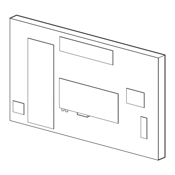
Mechanical Instructions LC4.1E AA EN 7 4. Mechanical Instructions Index of this chapter: Rear Cover Removal 1. Service Position 2. Rear Cover Removal 3. Power Supply Unit Removal 4. TV & Scaler Board Removal 5. Side I/O Panel Removal 6. Top Control Panel Removal 7. - Page 8 EN 8 LC4.1E AA Mechanical Instructions TV & Scaler Board Removal Audio Amplifier Panel Removal E_14520_037.eps 160904 E_14520_039.eps 160904 Figure 4-5 TV & Scaler board removal Figure 4-7 Audio amplifier panel removal 1. Disconnect all cables from the TV & Scaler board.
-
Page 9: Service Modes, Error Codes, And Faultfinding
Service Modes, Error Codes, and Fault Finding LC4.1E AA EN 9 5. Service Modes, Error Codes, and Fault Finding Index of this chapter: How to enter 1. Test Points To enter SDM, use one of the following methods: 2. Service Modes •... - Page 10 EN 10 LC4.1E AA Service Modes, Error Codes, and Fault Finding • How to exit Europe: T= 1 page TXT, F= Full TXT, V= Voice Switch the set to STANDBY by pressing the mains button on control. • the remote control transmitter or the television set.
- Page 11 Service Modes, Error Codes, and Fault Finding LC4.1E AA EN 11 5.2.3 Customer Service Mode (CSM) Problems and Solving Tips Related to CSM Purpose 5.3.1 Picture Problems The Customer Service Mode shows error codes and information on the TV’s operation settings. The call centre can...
- Page 12 5.4.1 Introduction 1. First, install the ComPair Browser software (see the Quick ComPair (Computer Aided Repair) is a service tool for Philips Reference Card for installation instructions). Consumer Electronics products. ComPair is a further 2. Connect the RS232 interface cable between a free serial...
- Page 13 Service Modes, Error Codes, and Fault Finding LC4.1E AA EN 13 7. Plug the mains adapter in a mains outlet, and switch the – To enter SAM, press the following key sequence on the interface “ON”. The green and red LEDs light up together.
- Page 14 EN 14 LC4.1E AA Service Modes, Error Codes, and Fault Finding 5.7.4 Fault Finding and Repair Tips Power Supply Check fuses Notes: This power supply contains three fuses. One is near the mains • It is assumed that the components are mounted correctly inlet (marked on the board as 1102) and two other are near the with correct values and no bad solder joints.
-
Page 15: Block Diagrams, Testpoint Overviews, And Waveforms
Block Diagrams, Testpoint Overviews, and Waveforms LC4.1E AA 6. Block Diagrams, Testpoint Overviews, and Waveforms Wiring Diagram TOP CONTROL 1308 LCD SCREEN (LVDS) CONNECTION Rigth Left Speaker Speaker INVERTER 1706 AUDIO AMPLIFIER BACK (5W) LIGHT CONNECTION LCD SCREEN 1910 1206... -
Page 16: Block Diagram Audio & Video
Block Diagrams, Testpoint Overviews, and Waveforms LC4.1E AA Block Diagram Audio & Video TUNER + VIF HERCULES (IF+VIDEO) +5VSW +VTUN 7011 - IF F312 7014 I044 1328 VIF2 2321 4327 F306 1302 R_SDTV Input Sound CVBS1 7013 VIF1 Tr aps... -
Page 17: Block Diagram Scaler & Supply
Block Diagrams, Testpoint Overviews, and Waveforms LC4.1E AA Block Diagram Scaler & Supply PCHD-IO SCALER (ANA IN) SCALER (LVDS, TTL OUT) 1404 F534 7401 PAN_VCC GM5221 RED_PR 7461 +5VSW VGA_5V FROM R_SDTV LV_E0_TX0- LV_E0_TX0- GREEN_Y 6460 G_SDTV R_PR+ LV_E1_TX0+ LV_E1_TX0+... - Page 18 Block Diagrams, Testpoint Overviews, and Waveforms LC4.1E AA Testpoint Overview TV & Scaler Board (Top Side) I413 SERVICE TESTPOINT I414 I415 I416 I417 I418 I419 I420 I421 I422 I424 I425 I426 I427 I428 I429 I430 I431 I432 I434 I436 I437...
-
Page 19: Testpoint Overview Tv & Scaler Board
Block Diagrams, Testpoint Overviews, and Waveforms LC4.1E AA Testpoint Overview TV & Scaler Board (Bottom Side) F002 C4 F487 D2 I041 D3 I467 D2 F003 D6 F488 D2 I042 D3 I470 D1 F004 B4 F489 D1 I043 D3 I471 D1... - Page 20 Block Diagrams, Testpoint Overviews, and Waveforms LC4.1E AA Testpoint Overview Front IR / LED Panel (Bottom Side) F801 A1 F802 A1 F803 A1 F804 A1 Personal Notes: E_14520_024.eps 3139 123 5836.1 150904 E_06532_012.eps 060804...
- Page 21 Block Diagrams, Testpoint Overviews, and Waveforms LC4.1E AA I2C IC Overview I2C BUS INTERCONNECTION DIAGRAM HERCULES TUNER IF SCALER +3V3STBY +3V3STBY (LVDS) 3096 3088 F303 7011 +3V3STBY +3V3STBY 3083 PROCESSOR 3084 PART OF VIDEO- F302 PROCESSER 3303 3302 3430 3431...
-
Page 22: Supply Voltage Overview
Block Diagrams, Testpoint Overviews, and Waveforms LC4.1E AA Supply Voltage Overview TV SUPPLY TUNER IF SUPPLY SCALER IO PANEL +3V3STBY 1910 (INVERTER) +3V3STBY F903 +5VSW 5520 AUD_SUP +5VSW AUD_SUP 1200 +VTUN +5VSW +VTUN +5VSW 6460 F905 +3V3STBY +3V3STBY +3V3STBY +3V3STBY... -
Page 23: Circuit Diagrams And Pwb Layouts
Circuit Diagrams and PWB Layouts LC4.1E AA 7. Circuit Diagrams and PWB Layouts TV & Scaler Board: Tuner & VIF 1302 A2 1331 B1 2307 D4 2313 E5 2321 C6 3309 B6 3316 E6 3321 C7 3325 C7 4318 E7... -
Page 24: Hercules
Circuit Diagrams and PWB Layouts LC4.1E AA TV & Scaler Board: Hercules 3070 D2 I038 B9 1001 D3 1009 H4 3072 C3 I039 C11 1010 A12 3073 C2 I040 B10 2002 H2 3074 H4 I041 C11 HERCULES 2004 C4 3075 B2... -
Page 25: Hercules Supply
Circuit Diagrams and PWB Layouts LC4.1E AA TV & Scaler Board: Hercules Supply 1006 B1 1007 B1 1008 A1 2001 B7 HERCULES-SUPPLY I093 I095 2003 C4 6061 HERC_RESET 2012 B5 +1V8_B 2014 C1 BAS316 +3V3STBY 7061 2015 E4 7070 3089... -
Page 26: Audio Amplifier (2X2W)
Circuit Diagrams and PWB Layouts LC4.1E AA TV & Scaler Board: Audio Amplifier (2x2W) 1701 B8 1706 D5 2703 C3 2704 C4 AUDIO AMPLIFIER (2x2W) 2705 C4 2712 B3 2714 A6 2718 B3 2719 A5 FOR 14, 15, 17 INCH... -
Page 27: Tv-Supply
Circuit Diagrams and PWB Layouts LC4.1E AA TV & Scaler Board: TV Supply 1910 A1 2910 E8 2911 E9 TV-SUPPLY 2920 F3 2921 F4 2930 D3 2931 C6 2933 D6 2934 D4 2935 D8 F903 AUD_SUP 2936 A2 *EMC 2936... -
Page 28: Scaler
Circuit Diagrams and PWB Layouts LC4.1E AA TV & Scaler Board: Scaler 1403 G5 1405 E2 1406 D2 1407 D2 SCALER 2401 D9 2402 G10 2403 D9 2404 G10 2405 G10 2406 G11 +1V8_AVDD +3V3_AVDD 2407 D9 2408 D10 2409 D10... -
Page 29: Scaler Lvds
Circuit Diagrams and PWB Layouts LC4.1E AA TV & Scaler Board: Scaler LVDS 1401 A1 I409 B6 1402 C5 I410 B3 1404 C8 I411 B3 +3V3_AVDD 1409 A3 I412 B3 +3V3STBY SCALER LVDS +3V3STBY 2446 C5 I413 C5 FOR DEV ONLY... -
Page 30: Scaler Io
Circuit Diagrams and PWB Layouts LC4.1E AA TV & Scaler Board: Scaler IO 1461 B1 4462 B5 I493 F3 1462 A8 4463 F6 I494 F3 2451 D5 4464 F6 I496 F3 2460 C2 4510 D7 I510 E8 SCALER IO 2461 D4... -
Page 31: Supply
Circuit Diagrams and PWB Layouts LC4.1E AA TV & Scaler Board: Supply TV & Scaler Board: Rear IO Scart 1951 A4 2961 C2 2995 E1 2998 B1 5955 B2 5958 A2 5961 B4 7954 C3 F952 D1 I952 B3 I955 C2... - Page 32 Circuit Diagrams and PWB Layouts LC4.1E AA Layout TV & Scaler Board (Top Side) 1006 B3 2419 D5 3389 B4 1007 B3 2420 C4 3390 D4 1008 B4 2428 B4 3391 D4 1009 D3 2437 C4 3394 C2 1010 D6...
- Page 33 Circuit Diagrams and PWB Layouts LC4.1E AA Layout TV & Scaler Board (Bottom Side) 1328 C4 2425 C2 3070 B4 3469 D2 5520 D1 1329 C5 2426 C2 3072 B4 3470 D2 5920 E4 1330 D4 2427 C2 3073 B4...
-
Page 34: Side Av Panel
Circuit Diagrams and PWB Layouts LC4.1E AA Side AV Panel 1101 A1 7101 C1 1102-1 D1 F101 A5 1102-2 E1 F102 A5 SIDE AV 1102-3 E1 F105 F5 1104 A4 F106 B8 1108 1105 D8 F107 B8 1106 B8 F108 B8... - Page 35 Circuit Diagrams and PWB Layouts LC4.1E AA Layout Side AV Panel (Top Side) 1101 A2 1104 A1 1106 A4 1108 A2 1111 A1 2111 A4 1102 A3 1105 A3 1107 A3 1110 A3 1112 A1 2112 A4 E_14520_026.eps 3139 123 5831.1...
-
Page 36: Top Control Panel
Circuit Diagrams and PWB Layouts LC4.1E AA Top Control Panel Layout Top Control Panel (Top Side) 1308 A1 1309 A6 1310 A5 1311 A3 1312 A2 1313 A4 1308 B1 1309 C2 1310 C2 1311 C3 TOP CONTROL 1312 C3... - Page 37 Circuit Diagrams and PWB Layouts LC4.1E AA Audio Amplifier (2x5W) (20 & 23 inch) 1703 A1 1704 C8 1706 D1 1710 E1 AUDIO AMPLIFIER (2x5W) (FOR 20 & 23 INCH) 2703 D5 2712 B4 2713 B6 2714 B7 2715 B8...
- Page 38 Circuit Diagrams and PWB Layouts LC4.1E AA Audio Amplifier (2x5W) (20 & 23 inch) 1703 B3 1704 C2 1706 A3 2703 B3 2712 B3 2713 B1 2714 C2 2715 C3 2718 B3 2719 A1 2741 B3 2742 B3 2746 B3...
-
Page 39: Front Ir / Led Panel
Circuit Diagrams and PWB Layouts LC4.1E AA Front IR / LED Panel Layout Front IR / LED Panel (Top Side) 1870 A1 6801 A1 7802 A1 7805 A1 1870 B1 3801 B3 3805 D4 6801-1 B4 7802 C3 7805 E4... - Page 40 Circuit Diagrams and PWB Layouts LC4.1E AA Personal Notes: E_06532_013.eps 060804...
-
Page 41: Alignments
Alignments LC4.1E AA EN 41 8. Alignments General: The Service Default Mode (SDM) and Service Hardware Alignments Alignment Mode (SAM) are described in chapter 5. Menu navigation is done with the cursor Up, Down, Left or Right keys There are no hardware alignments foreseen for the LCD-TV. - Page 42 (no offset difference). Then the offset values for the Delta Cool Equipment and setting and Delta Warm mode can be selected. Note that the • E.g. Fluke 54200 or Philips PM5580. alignment values are non-linear. The range is: -50 to +50, 0 • 100% “8-step grey scale” pattern.
- Page 43 Alignments LC4.1E AA EN 43 8.3.5 Sound No adjustments needed for sound. The default values for the audio alignments are: • QSS: On • FMI: Off • NICAM Alignment: 63 • Lip Sync: Off • DBE: Off 8.3.6 Options Options are used to control the presence/absence of certain features and hardware.
- Page 44 EN 44 LC4.1E AA Alignments Table 8-2 Option codes (general overview for all displays) Bit (DEC) Option Description 7 (128) OP_PHILIPS_TUNER Philips Tuner available 6 (64) OP_FM_RADIO FM Radio available 5 (32) OP_LNA Low Noise Amplifier available 4 (16) OP_ATS...
-
Page 45: Circuit Descriptions
Circuit Descriptions, Abbreviation List, and IC Data Sheets LC4.1E AA EN 45 9. Circuit Descriptions, Abbreviation List, and IC Data Sheets • Index of this chapter Audio: The sound processor is part of the UOC processor 1. Introduction (called “Hercules”). The chassis has a FM Radio with 40 2. - Page 46 RGB/YPRPB input are not needed. One SCART- connector is used (SCART1). This connector is fully equipped. A Philips UR13xx Tuner with second input (for FM Radio) is The video part delivers the RGB signals to the Scaler IC.
- Page 47 Circuit Descriptions, Abbreviation List, and IC Data Sheets LC4.1E AA EN 47 Video: TV Part (diagrams A1, A2, and A3) when using SM5301BS, Low Pass Filter circuit is Video IF not needed. Otherwise, LPF circuit is needed. Scaler Hercules Analog Input Port...
- Page 48 Monitor Controller. mode. Due to the diversity involved, the data for the 2 bits are • On-chip 80C51 micro-controller from Philips being placed in the NVM location and it is required to write once Semiconductor UOCIII (Hercules) series. during startup.
-
Page 49: Abbreviation List
Digital Theatre Sound : AU Optronics Corp Supplier Digital Video Disc (14”) EEPROM Electrically Erasable and : LG.Philips LCD (15”, Programmable Read Only Memory 17”, 20”) Electronic Program Guide: system : Quanta Displays Inc used by broadcasters to transmit TV (23”) - Page 50 SC1-OUT SCART output of the MSP audio IC LATAM LATin AMerica SC2-B-IN SCART2 Blue in LC04 Philips chassis name for LCD TV 2004 SC2-C-IN SCART2 chrominance in project SC2-OUT SCART output of the MSP audio IC Liquid Crystal Display Short Circuit...
-
Page 51: Ic Data Sheets
Circuit Descriptions, Abbreviation List, and IC Data Sheets LC4.1E AA EN 51 Video Cassette Recorder Video Graphics Array Watch Dog WYSIWYR What You See Is What You Record: record selection that follows main picture and sound XTAL Quartz crystal YPbPr... - Page 52 EN 52 LC4.1E AA Circuit Descriptions, Abbreviation List, and IC Data Sheets 9.12.2 Diagram A2, Type TDA12029H (IC7011) A “ ” o µ & Pin configuration “stereo” and “AV-stereo” versions with Audio DSP AVL/SWO/SSIF/ REFIN/REFOUT P1.5/TX AUDIOIN5L P1.4/RX AUDIOIN5R P1.2/INT2...
- Page 53 Circuit Descriptions, Abbreviation List, and IC Data Sheets LC4.1E AA EN 53 9.12.3 Diagram A12, Type S9993CT (IC7808) BLOCK DIAGRAM RESET# CSDA Registers Slave CSCL DSDA ---------------- Slave Configuration DSCL Logic Block Aux Data Logic HDCP HDCP Block MCLK Keys...
-
Page 54: Spare Parts List
EN 54 LC4.1E AA Spare Parts List 10. Spare Parts List Set Level 2044 4822 126 13879 220nF +80-20% 16V 2407 2238 586 59812 100nF 20% 50V 0603 2045 5322 126 11583 10nF 10% 50V 0603 2408 2238 586 59812 100nF 20% 50V 0603... - Page 55 Spare Parts List LC4.1E AA EN 55 2930 4822 124 80791 470µF 20% 16V 3101 4822 051 30151 150Ω 5% 0.062W 3479 4822 117 12139 22Ω 5% 0.062W 2931 4822 126 13881 470pF 5% 50V 3102 4822 117 12891 220kΩ 1% 3480 4822 117 12139 22Ω...
- Page 56 EN 56 LC4.1E AA Spare Parts List 6060 9322 102 64685 UDZ2.7B 3105 4822 051 30759 75Ω 5% 0.062W 5710 4822 157 11716 Bead 30Ω at 100MHz 6061 4822 130 11397 BAS316 3106 4822 051 30759 75Ω 5% 0.062W 6073...
-
Page 57: Revision List
Revision List LC4.1E AA EN 57 11. Revision List Manual xxxx xxx xxxx.0 • First release.
Need help?
Do you have a question about the LC4.1E AA and is the answer not in the manual?
Questions and answers