Advertisement
Quick Links
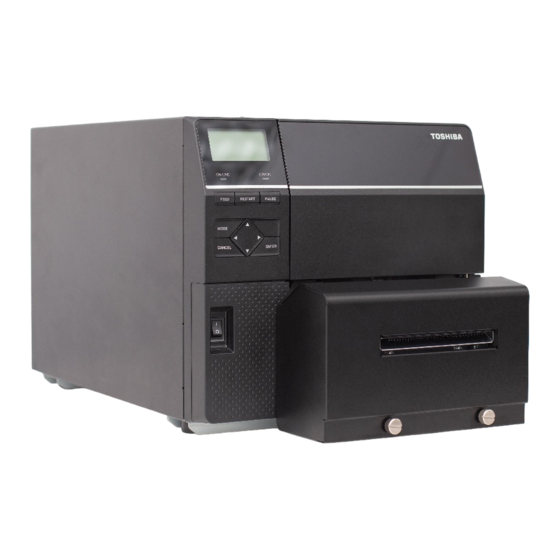
Disc Cutter Module ディスクカッターモジュール
B-EX206-QM-R
Thank you for purchasing TOSHIBA B-EX206-QM-R Disc Cutter Module.
The B-EX206-QM-R is exclusively for the B-EX6T series.
このたびは、ディスクカッター B-EX206-QM-R をお買い上げ頂き、誠にありがとうございます。
本キットは B-EX6T シリーズ用カッターモジュールです。
1. Follow all manual instructions. Failure to do so could create safety hazards such as fire or
electrocution.
Manual instructions must be followed when installing option kits or adding cables to avoid system
failures and to insure proper performance and operation.
Failure to follow manual instructions or any unauthorized modifications, substitution or change to this
product will void the limited product warranty.
2. Turn the power OFF and disconnect the power cord before installing this optional kit.
3. Be careful not to pinch your fingers or hands with the covers.
4. The print head and stepping motor becomes very hot immediately after printing. Do not touch the print
head, stepping motor and around it right after printing, or you may get burned.
5. When opening the top cover, it must be fully opened. Failure to do this may cause the top cover to close
under its own weight, resulting in an injury.
1. 組み込む前にプリンタの電源スイッチをOFFにし、電源プラグをコンセントから抜くこと
2. カバーで指や手を挟まないよう注意すること
3. カッターモジュールの取付け・清掃時、カッターの刃に直接触れないこと
警告
4. トップカバーは左側へ倒すように全開にすること
5. 印字直後は、印字ヘッド、ステッピングモーターおよびその周辺部に手を触れないこと
電源がONの状態で組み込むと、火災・感電・けがの恐れがあります。また、プリンタ内
部の電気回路保護の為、プリンタの電源 OFF 後1分以上経過してからカッター
モジュールハーネスの着脱を行うこと。
けがの原因となる恐れがあります。
中途半端な状態にしておくと勝手に閉まり、けがの原因となることがあります。
やけどの原因となることがあります。
*00TSCC0315101*
WARNING!
Power Switch
1
Power Cord
EO2-38108
Advertisement

Related Manuals for Toshiba B-EX206-QM-R


Summary of Contents for Toshiba B-EX206-QM-R
- Page 1 EO2-38108 Disc Cutter Module ディスクカッターモジュール B-EX206-QM-R *00TSCC0315101* Thank you for purchasing TOSHIBA B-EX206-QM-R Disc Cutter Module. The B-EX206-QM-R is exclusively for the B-EX6T series. このたびは、ディスクカッター B-EX206-QM-R をお買い上げ頂き、誠にありがとうございます。 本キットは B-EX6T シリーズ用カッターモジュールです。 WARNING! 1. Follow all manual instructions. Failure to do so could create safety hazards such as fire or electrocution.
- Page 2 EO2-38108 NOTE: This module cannot be used together with the B-EX906-H-QM-R strip module. When this cutter is used together with an RFID module, be sure to install the RFID module prior to the cutter. 補足: 本モジュールは、剥離モジュール B-EX906-H-QM-R と併用できません。 カッターモジュールの他に RFID キットを組み込む場合は、先に RFID キットを取り付けてください。 1 APPLICABLE MODEL 対象モデル...
- Page 3 EO2-38108 Difference between Type 1 and Type 3 cutter: タイプ1用とタイプ3用のカッターの違いについて The B-EX206 disc cutter module is basically the same except for the Paper Guide used for Type 1 and Type 3. To attach to Type 3, the parts shown in P4 need to be changed in advance. B-EX206 ディスクカッターモジュールは下記に示すペーパーガイド形状を除いて基本的には同じです。...
- Page 4 EO2-38108 B-EX6 TYPE3 装着時の調整方法 Adjustment Method for B-EX6 TYPE3 Before installing the disk cutter unit for B-EX6 Type3, exchanging of Paper Guide and adjustment has to be made to set the clearance of the cutter. B-EX6 Type3 へカッターを取り付ける前に、用紙ガイドの交換と用紙ガイドの隙間の調節をします。 1. Loosen the two FL -3 x 6 screws holding the metal guide. 金属製の用紙ガイドを固定しているフランジネジ2本(FL-3x6)を緩めます。...
- Page 5 EO2-38108 3. INSTALLATION PROCEDURE 組込手順 重要:プリンタの電源をオフした後、1分以上経過するまでお待ちください。 ※ 本書は海外モデルの写真を使用しており国内モデルとは外観や標準装備品が異なりますが、組込手順は共通 です。 3.1 Removing the Covers カバーの取り外し 1. Turn the printer power off and disconnect the Power Cord. プリンタの電源スイッチを OFF にし、電源プラグをコンセントから抜きます。 2. Remove the three B-4x5 screws from the Side Panel (L). 左サイドカバーからネジ3本(B-4x5)を外します。 3.
- Page 6 EO2-38108 5. Release the tab on the right end by pushing it, then remove the Front Panel (Right) . フロントパネル右端のタブを押し上げてフックを解除し、フロントパネル(右)を本体から取り外します。 Front Panel (Right) タブ フロントパネル(右) 6. Remove the Front Panel (Left). フロントパネル(左)を本体から取り外します。 Front Panel (Left) フロントパネル(左) 3.2 Mounting the Cutter Unit カッターユニットの取り付け 1.
- Page 7 EO2-38108 2. Open the Print Head Block. 印字ヘッド機構部を持ち上げます。 Print Head Block 印字ヘッド機構部 3. Push the hook through the rectangle hole with a tool with a fine tip to remove the Platen Holder Cover. 先の細いツールを角穴に差し込んでフックを解除し、プラテンホルダーカバーを取り外します。 Platen Holder Cover Hook プラテンホルダーカバー フック Push 押す...
- Page 8 EO2-38108 5. Restore the Platen Holder Cover. プラテンホルダーカバーを元の位置に戻します。 NOTE: The strip plate is not used. Keep it safe for future use. 補足:剥離板は使用しませんので、大切に保管しておいてください。 Platen Holder Cover プラテンホルダーカバー 6. Remove 2 screws and Cutter Cover カッターカバーを化粧ネジ2本で外します Plastic Head Screw 化粧ネジ Plastic Head Screw 化粧ネジ...
- Page 9 EO2-38108 8. Attach the Cable Clamp to the printer base. Fasten the Harness Ass’y with the Cable Clamp. ケーブルクランプをプリンタベースに取り付け、カッターハーネスをまとめます。 Cable Clamp Harness Ass’y ケーブルクランプ カッターハーネス Printer Base Cable Clamp プリンタベース ケーブルクランプ NOTE: Make sure the wires will not touch or obstruct any moving parts. お願い:カッターハーネスが可動部に触れて動作の妨げにならないように気をつけて下さい。...
- Page 10 EO2-38108 10. Secure the right side of the Cutter Unit with the ST-3x6 screw. カッターユニットの右側を付属のネジ(ST-3x6)1本で固定します。 ST-3x6 Screw ネジ(ST-3x6) 11. Secure the bottom of the Cutter Unit with the two M-4x6 screws. カッターユニットの下部を付属のネジ(M-4x6)2本で固定します。 Cutter Unit カッターユニット M-4x6 Screw ネジ(M-4x6)
- Page 11 EO2-38108 12. Insert the connector of the Harness Ass’y into the hole in the Main Frame, then fit the Cord Bush into the hole. まずカッターハーネスのコネクタをメインフレームの丸穴に通してからコードブッシュを穴に取り付け ます。 Main Frame メインフレーム Hole 丸穴 Harness Ass’y Cord Bush カッターハーネス コードブッシュ NOTE: Make sure the wires will not touch or obstruct any moving parts. お願い:カッターハーネスが可動部に触れて動作の妨げにならないように気をつけて下さい。...
- Page 12 EO2-38108 3.3 Wiring of the Harness Ass’y カッターハーネスの引き回し 1. Pass the Harness Ass’y through the Cable Protector. PC板側からカッターハーネスを引き出し、ケーブルガードの内側に通します。 Harness Ass’y カッターハーネス Cable Protector ケーブルガード 2. Fasten the Harness Ass’y with the Cable Clamp. カッターハーネスを 1 番下のケーブルクランプで固定します。 3. Connect the Harness Ass’y to J11 on the Main PC board. カッターハーネスをメイン...