Table of Contents
Advertisement
CLIMATE CONTROL
SmartStart SMRTSTACRV
RV Soft Start Accessory
EN
Installation and Operating Manual . . . . . . . . . . . 3
WARNING
This product can expose you to chemicals including
lead and di(2-ethylhexyl)phthalate, which are known
to the State of California to cause cancer, birth
defects or other reproductive harm.
For more information, go to
www.P65Warnings.ca.gov
ACCESSORIES
120VAC
RUN
Item# 9610002970
FAULT LED
RUN
© 20
Design Protected
Form No. 4445103956 2023-06-21
Advertisement
Table of Contents

Related Manuals for Dometic SmartStart SMRTSTACRV


Summary of Contents for Dometic SmartStart SMRTSTACRV
- Page 1 120VAC Item# 9610002970 FAULT LED © 20 Design Protected SmartStart SMRTSTACRV RV Soft Start Accessory Installation and Operating Manual ... 3 WARNING This product can expose you to chemicals including...
- Page 2 RV Soft Start Accessory Copyright © 2023 Dometic Group. The visual appearance of the contents of this manual is protected by copyright and design law. The underlying technical design and the products contained herein may be protected by design, patent or be patent...
-
Page 3: Table Of Contents
This product manual, 1 Related documents including the instructions, guidelines, and warnings, and related documentation, may be subject to changes and updates. For up-to- date product information, please visit www.dometic.com. Find the installation and operation Contents manual on-line in French at http://documents.dometic.com/... -
Page 4: Understand Signal Words
• The installation must comply with all applicable local or national codes, including the latest edition of the • Use only Dometic replacement parts and following standards: components that are specifically approved for use with the appliance. -
Page 5: Intended Use
This product is compatible with most 120 VAC RV AC units. This manual specifically describes installation for the Dometic Brisk II, Penguin II, Blizzard NXT, and FreshJet 3 Series Mechanical units. Additional AC units may be added at future dates. -
Page 6: Component Locations
General information RV Soft Start Accessory 4 .3 Component locations This section shows the Dometic Brisk II, Penguin II, Blizzard NXT, and FreshJet AC unit dimensions, the AC shroud screw locations, and the inside component views. It also shows the component views for the device. - Page 7 RV Soft Start Accessory General information 3 Blizzard NXT AC unit shroud dimensions 4 FreshJet (FJX3000 and FJX4000 series 13.9 in. (353 mm) 18.0 in. (457 mm) 13.8 in. (351 mm) Air flow clearance clearance area (shaded) 40.0 in. (1016 mm) 29.6 in.
- Page 8 General information RV Soft Start Accessory 5 Brisk II AC unit components and screw locations 6 Penguin II AC unit components and screw locations AC shroud Fan motor AC shroud Compressor AC shroud screws Compressor AC shroud screws Fan motor Foam shroud Condenser Fan Foam shroud...
- Page 9 RV Soft Start Accessory General information 7 Blizzard NXT AC unit components and screw locations 8 FreshJet AC unit components and screw locations AC shroud Electrical box AC shroud Condenser Fan AC shroud screws Fan motor AC shroud screws Compressor EPP foam Capacitor Foam shroud...
-
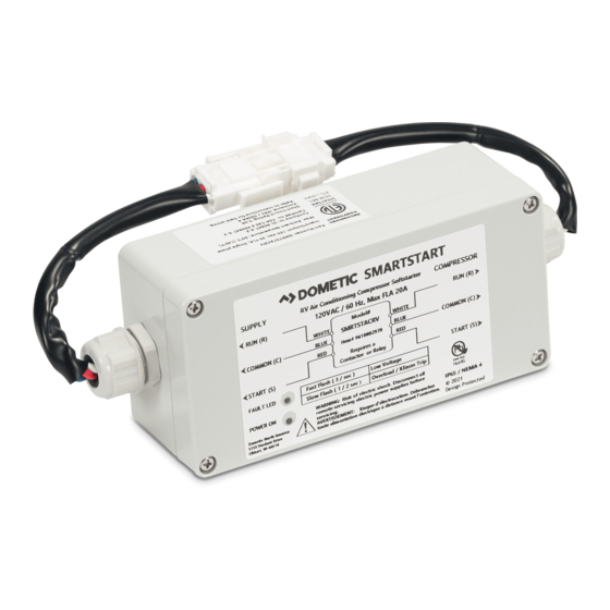
Page 10: Model Identification
Specifications RV Soft Start Accessory 4 .5 Data plate This section describes the device data plate. 120VAC Item# 9610002970 FAULT LED © 20 Design Protected 11 Device data plate The device data plate provides information specific to 10 Device components the device and is located on the device cover. - Page 11 RV Soft Start Accessory Wiring diagrams Compressor Compressor Motor Motor GRN/YEL GRN/YEL O.L. O.L. 6 Pin Conn 6 Pin Conn Herm Comp Start Assist GRN/YEL Run Cap Start PTCR * Not used on Herm some models GRN/YEL Run Cap * Not used on Comp.
- Page 12 Wiring diagrams RV Soft Start Accessory 16 FreshJetX3 series AC unit wiring diagram 17 FreshJetX4 series AC unit wiring diagram...
-
Page 13: Preinstallation
RV Soft Start Accessory Preinstallation 7 Preinstallation – FreshJet - If the z-bracket slants right, go to “Installation” on page 16, otherwise go to This section describes the bracket preparation required step 2. before installing the device onto the AC unit. 2. Complete steps 1–5 in “Preparing the device” on page 14. -
Page 14: Bracket Assembly
Preinstallation RV Soft Start Accessory 7 .1 .2 Penguin II and Blizzard NXT 5. Carefully turn the device on its side. configuration 6. Continue with the assembly: The mounting bracket should already be attached to – For Brisk II AC units, go to “Assembling the the device. -
Page 15: Attaching The Hose Clamp
RV Soft Start Accessory Preinstallation 4. Using the #2 Phillips screwdriver, push two bracket screws through the holes in the device and then through the small holes in the z-bracket flange. 5. With the mounting bracket on its side, fit the mounting bracket slots onto the exposed bracket screws. -
Page 16: Installation
Installation RV Soft Start Accessory 7. Aligning the fiber optic rods on the underside of device cover to the LEDs in the device, replace the device cover. 8. Tighten the device cover screws to 8.8 in. lbs (1 Nm). 9. Go to “Installation” on page 16. 8 Installation WARNING: Fire or electric shock hazard . -
Page 17: Installing The Device - Brisk Ii
RV Soft Start Accessory Installation 8 .1 .1 Removing the shrouds This section describes how to install the device. The installation procedures and components vary by the AC unit model. Go to “Installing the device - Brisk II” on Brisk II page 17. - Page 18 Installation RV Soft Start Accessory 25 Removing the electrical box cover 26 Disconnecting the compressor wires from the capacitor Electrical box cover Electrical box Capacitor Red and white compressor screws cover wires Electrical box 1. Using a multimeter, confirm that the capacitor is fully 3.
- Page 19 RV Soft Start Accessory Installation 8 .1 .3 Installing the new supply wire 3. Using the 5/16 in. deep well nut driver, locate and remove the compressor cap nut and compressor cap harness from the top of the compressor. 4. Disconnect the white, red, and blue factory compressor wires from the compressor.
- Page 20 Installation RV Soft Start Accessory 5. Using the 5/16 in. deep well nut driver, insert the 11. On the capacitor, connect the white wire to the COM outer strain relief screw into the strain relief and terminal. tighten until snug. 12.
- Page 21 Ensure the device shifts towards the condenser fan blade. See “Component locations” on 1. Connect the supply wire harness to the supply side page 6. If it does not, contact Dometic of the device. If necessary, pull more of the blue wire customer service.
-
Page 22: Installing The Device - Penguin Ii
Installation RV Soft Start Accessory 8 .2 Installing the device - Penguin II This section describes how to access the installation area, disconnect the existing wiring, mount the device, install and connect the new wiring, and close the unit after completing the installation in a Penguin II AC unit. 8 .2 .1 Removing the covers 35 Connecting the compressor wire harness to the device... - Page 23 RV Soft Start Accessory Installation 38 Disconnecting the compressor wires from the capacitor Strain relief Motor starter capacitor Wire tie Capacitor Motor White booted 37 Disconnecting the blue wire from the relay block starter compressor wire Electrical box cover Relay block Holding clamp Red compressor wire screws...
- Page 24 Installation RV Soft Start Accessory 9. If the motor starter comes out of its holding clamp, 8 .2 .3 Mounting the device return it to the holding clamp. 10. Using a 6 in. (152 mm) length of electrical tape, secure the motor starter capacitor wires together and cover the terminal ends.
- Page 25 RV Soft Start Accessory Installation 8 .2 .4 Connecting the supply wire 8 .2 .5 Connecting the compressor wire harness harness 41 Connecting the supply wire harness Supply wire Red supply wire to harness HERM terminal Blue supply wire White supply wire to 42 Connecting the compressor wire harness COM terminal Compressor cap nut...
-
Page 26: Installing The Device -Blizzard Nxt
Installation RV Soft Start Accessory 8 .2 .6 Replacing the covers 8 .3 .1 Removing the covers 1. Replace the reserved gasket putty to seal the holes Turn the AC shroud upside down to store the where the wire harness passes in and out of the screws and other small parts removed during the housing wall: installation process. - Page 27 RV Soft Start Accessory Installation 2. Remove the internal foam shroud by pulling up 5. Reconnect the piggy-back connector to its original vertically on the sides and set aside. terminal location. 3. Expose the electrical box cover screws by pulling forward on the electrical box foam.
- Page 28 Installation RV Soft Start Accessory 8 .3 .3 Disconnecting the motor starter 8 .3 .4 Connecting the new supply wire capacitor harness 47 Connecting the wires 46 Disconnecting the motor starter Supply wire harness White supply wire Capacitor Motor starter Cable jacket Wire tie Motor starter capacitor...
- Page 29 RV Soft Start Accessory Installation 8 .3 .5 Connecting the new compressor wire harness NOTICE: When routing the compressor wire harness, the compressor wire harness should route under the foam. Failure to follow this notice could cause the fan motor shaft to damage the compressor wire harness. 48 Routing the supply wire harness Supply wire harness path Strain relief...
- Page 30 Installation RV Soft Start Accessory 2. Route the compressor wire harness, ensuring it 4. Place the device on the fan motor, ensuring the hose passes over the existing wire ties. clamp remains in the gap between the fan motor and the mounting flange.
-
Page 31: Installing The Device - Freshjet 3 Series
RV Soft Start Accessory Installation 8 .3 .7 Connecting the harnesses to the 8 .4 Installing the device - FreshJet 3 device Series Mechanical NOTICE: Do not force the AC shroud during removal. Failure to follow this notice can damage or break the screw holes and require an AC shroud replacement. - Page 32 Installation RV Soft Start Accessory 8 .4 .3 Removing the nuts and washers AC shroud EPP foam AC shroud screws 1. Using the #2 Phillips screwdriver, remove and set aside the six AC shroud screws and the AC shroud. The AC shroud should lift off easily. If it does not, verify all the AC shroud screws have been removed.
- Page 33 RV Soft Start Accessory Installation 8 .4 .4 Placing the device 8 .4 .5 Locate the capacitor 58 Device placed on mounting studs 59 Capacitor location Compressor LEDs on device Capacitor Condenser fan Mounting nut 1. Locate the capacitor. 1. Place the supply side of the device towards the 2.
- Page 34 Installation RV Soft Start Accessory 8 .4 .8 Placing the connector and routing 2. Attach the AC pigtail to the female 6-pin connector of the supply harness. If the AC pigtail is already the harness connected to the ADB switch box follow step 3. 3.
- Page 35 RV Soft Start Accessory Installation 8 .4 .9 Attaching the harness wires WARNING: Electric shock hazard . There is a risk of electrical shock from the energy stored in the capacitors. Wait for five minutes after the shutdown of equipment before performing any installation activity.
- Page 36 Installation RV Soft Start Accessory 1. Replace the lid onto the capacitor. Ensure that all wires are routed through the opening in the lid. Do not pinch wires under lid. 2. Use the saved putty to secure all the wires into the wire channel.
- Page 37 RV Soft Start Accessory Installation 8 .4 .12 Securing the harness to device NOTICE: Failure to route the wires correctly can result in damage to the AC condenser fan blade. 69 Supply and compressor harness connected to the device Supply harness Compressor harness connected to device connected to device...
- Page 38 Installation RV Soft Start Accessory 8 .4 .13 Securing the harnesses 4. Gather the factory compressor wires together and bundle. Leave approximately 4–6 in. (101–152 mm) of lead outside of the bundle so they will fit in the EPP foam housing. 5.
-
Page 39: Operation
• Verify the thermostat is functioning properly; second). contact Dometic Customer Support. • Contact Dometic Customer Support. If the AC is running on a power Check the power rating of the power inverter. inverter, the AC has exceeded the inverter’s power rating. -
Page 40: Disposal
Limited 1-year warranty LIMITED 1-YEAR WARRANTY AVAILABLE AT DOMETIC.COM/EN-US/TERMS-AND-CONDITIONS- CONSUMER/WARRANTY. IF YOU HAVE QUESTIONS, OR TO OBTAIN A COPY OF THE LIMITED WARRANTY FREE OF CHARGE, CONTACT: DOMETIC CORPORATION CUSTOMER SUPPORT CENTER 5155 VERDANT DRIVE ELKHART, INDIANA 46516 1-800-544-4881... - Page 41 RV Soft Start Accessory...
- Page 42 RV Soft Start Accessory...
- Page 43 RV Soft Start Accessory...
- Page 44 .com YOUR LOCAL YOUR LOCAL YOUR LOCAL DEALER SUPPORT SALES OFFICE dometic .com/dealer dometic .com/contact dometic .com/sales-offices...
Need help?
Do you have a question about the SmartStart SMRTSTACRV and is the answer not in the manual?
Questions and answers