
Related Manuals for Samson 3371


Summary of Contents for Samson 3371
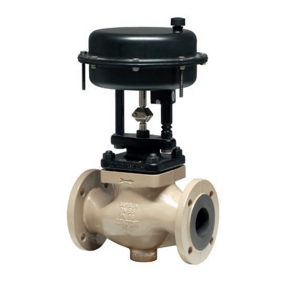
- Page 1 EB 8317 EN Translation of original instructions Type 3371 with 120 cm² actuator area Type 3371 with 350 cm² actuator area Type 3371 Pneumatic Actuator Actuator area: 120 and 350 cm² Edition April 2021...
- Page 2 Note on these mounting and operating instructions These mounting and operating instructions assist you in mounting and operating the device safely. The instructions are binding for handling SAMSON devices. The images shown in these instructions are for illustration purposes only. The actual product may vary.
-
Page 3: Table Of Contents
Contents Safety instructions and measures ..............1-1 Notes on possible severe personal injury ............1-4 Notes on possible personal injury ..............1-4 Notes on possible property damage .............1-6 Warnings on the device ................1-6 Markings on the device ................2-1 Actuator nameplate ..................2-1 Design and principle of operation ...............3-1 Direction of action ..................3-1 Signal pressure routing ................3-1 3.2.1... - Page 4 Removal ....................11-1 11.1 Removing the actuator from the valve ............11-2 11.2 Relieving the spring compression in the actuator ..........11-2 Repairs ....................12-1 12.1 Returning devices to SAMSON ..............12-1 Disposal ....................13-1 Certificates ....................14-1 Annex......................15-1 15.1 Tightening torques, lubricants and tools ............15-1 15.2 Spare parts ....................15-1...
-
Page 5: Safety Instructions And Measures
SAMSON. SAMSON does not assume any liability for damage resulting from the failure to use the de- vice for its intended purpose or for damage caused by external forces or any other external factors. - Page 6 Î Check with the plant operator for details on further protective equipment. Revisions and other modifications Revisions, conversions or other modifications of the product are not authorized by SAMSON. They are performed at the user's own risk and may lead to safety hazards, for example. Fur- thermore, the product may no longer meet the requirements for its intended use.
- Page 7 REACH regulation: Information on safe use of the part affected u www.samsongroup.com > About SAMSON > Material Compliance > REACH If a device contains a substance which is listed as being a substance of very high concern on the candidate list of the REACH regulation, this circumstance is indicated on the SAMSON delivery note.
-
Page 8: Notes On Possible Severe Personal Injury
Safety instructions and measures 1.1 Notes on possible severe personal injury DANGER Risk of bursting in the actuator. Actuators are pressurized. Improper opening can lead to actuator components burst- ing. Î Before starting any work on the actuator, depressurize all plant sections affected and the actuator. - Page 9 Safety instructions and measures WARNING Risk of personal injury when the actuator vents. The actuator is operated with air. As a result, air is vented during operation. Î Install the control valve in such a way that vent openings are not located at eye level and the actuator does not vent at eye level in the work position Î...
-
Page 10: Notes On Possible Property Damage
Risk of actuator damage due to the use of unsuitable tools. Certain tools are required to work on the actuator. Î Only use tools approved by SAMSON (u AB 0100). Risk of actuator damage due to the use of unsuitable lubricants. The lubricants to be used depend on the actuator material. Unsuitable lubricants may corrode and damage surfaces. -
Page 11: Markings On The Device
(see Fig. 2-1). The nameplate of the phragm case. Type 3371 with 120 cm² actuator area is lo- It includes all details required to identify the cated on the bottom diaphragm case. The device (see Fig. 2-2): nameplate of the Type 3371 with 350 cm²... - Page 12 EB 8317 EN...
-
Page 13: Design And Principle Of Operation
With direc- tion of action "actuator stem extends", the ation compressed air is applied to the signal pres- The Type 3371 Pneumatic Actuators have an sure connection on the bottom diaphragm actuator area of either 120 or 350 cm². case. -
Page 14: Fail-Safe Action
A18 Diaphragm A10 Spring A26 Collar nut A11 Rod A30/ Stem connector clamps A12 Bushing A35 Pneumatic connection A13 Diaphragm plate A72 Rod nut A14 Diaphragm plate Fig. 3-1: Functional diagram of Type 3371 Actuator with 120 cm² actuator area EB 8317 EN... - Page 15 A54 Rod nut Actuator stem A33 Stem A60 Plate A10 Spring A40 Radial shaft seal A61 Pneumatic connection A15 Collar nut A41 Wiper ring Signal pressure connection (stem retracts) Fig. 3-2: Functional diagram of Type 3371 Actuator with 350 cm² actuator area EB 8317 EN...
-
Page 16: Actuator Stem Extends
Design and principle of operation 3.3.1 Actuator stem extends 3.4 Mounting types When the signal pressure is reduced or the There are two types of mounting depending control signal fails, the springs move the ac- on the valve/actuator combination: mount- tuator stem downward and close the globe ing using a crossbeam or mounting using valve. - Page 17 Design and principle of operation Fig. 3-4: Form C: mounting using rods (120 cm²) Fig. 3-5: Form C: mounting using rods (350 cm²) Table 3-1: Mounting types (see Fig. 3-3, Fig. 3-4 and Fig. 3-5) Actuator area 120 cm² 350 cm² Travel 15 mm 15 mm 30 mm Type ... Valve Valve size DN 3321 15 to 50 Form B –...
-
Page 18: Versions
3.5 Versions Note − Standard version of Type 3371 More information is available in Data Sheet (120 cm²) u T 8317. The housings of Type 3371 Pneumatic Actuators have an actuator area of 120 cm² and are made of die-cast alu- minum. − Standard version of Type 3371 (350 cm²) The housings of Type 3371 Pneumatic Actuators have an actuator area of 350 cm²... - Page 19 Design and principle of operation Table 3-2: Technical data for Type 3371 Pneumatic Actuator Actuator area 120 cm² 350 cm² Rated travel 15 mm 30 mm Stem Stem Stem Stem Stem Stem Stem Stem Fail-safe action retracts retracts extends extends retracts extends retracts extends (FE) (FE)
- Page 20 EB 8317 EN...
-
Page 21: Shipment And On-Site Transport
Risk of lifting equipment tipping over and damage. Report any damage to risk of damage to lifting accessories due to SAMSON and the forwarding agent exceeding the rated lifting capacity. (refer to delivery note). Î Only use approved lifting equipment and 3. -
Page 22: Transporting The Actuator
Shipment and on-site transport Transport instructions WARNING − Protect the actuator against external in- Risk of injury due to incorrect lifting without fluences (e.g. impact). the use of lifting equipment. − Do not damage the corrosion protection Lifting the actuator without the use of lifting (paint, surface coatings). -
Page 23: Storing The Actuator
Special storage instructions for elastomers Î Avoid long storage times. Elastomer, e.g. actuator diaphragm Î Contact SAMSON in case of different − To keep elastomers in shape and to pre- storage conditions or longer storage vent cracking, do not bend them or hang times. - Page 24 EB 8317 EN...
-
Page 25: Installation
5.2 Mounting the device it has become blocked (e.g. due to seizing up after remaining in the same Depending on the version, SAMSON control position for a long time), release any valves are either delivered with the actuator stored energy in the actuator (e.g. spring already mounted on the valve or the valve compression). - Page 26 Risk of actuator damage due to the use of high or low tightening torques. unsuitable tools. Observe the specified torques when tighten- Î Only use tools approved by SAMSON ing actuator components. Excessive tighten- (u AB 0100). ing torques lead to parts wearing out more quickly.
-
Page 27: Mounting The Actuator Onto The Valve
Installation 5.2.1 Mounting the actuator 5. Fail-safe action "stem extends": position the stem connector clamps (A30) and onto the valve screw them tight. Observe tightening torques. Fail-safe action "stem retracts": apply The valve and actuator are assembled with pressure to the top diaphragm chamber special attention paid to the actuator's bench until the actuator stem touches the plug range and direction of action. - Page 28 Installation Valve bonnet Central nut Crossbeam Rod nut Fig. 5-2: Mounting using crossbeam (form B) Valve bonnet Bushing Rod nut Fig. 5-3: Mounting using rods (form C), 120 cm² b) 350 cm² actuator area bottom case do not turn. Observe tight- ening torques. Mounting using rods (form C, see Fig. 5-4) 5. Fail-safe action "stem extends": position 1. Remove the clamps of the stem connector the stem connector clamps and screw from the actuator.
-
Page 29: Changing The Mounting Type
Installation A33/A51 Valve bonnet A33/A51 Rod Rod nut Plate Fig. 5-4: Mounting using rods (form C), 350 cm² 5.3 Changing the mounting 1. Remove the clamps of the stem connec- tor. type 2. Unscrew the central nut (98). The mounting type of actuators with 120 cm² 3. -
Page 30: Changing The Mounting Type To Mounting Using A Crossbeam (Form C To Form B)
Installation nector and screw them tight. Observe 9. Fail-safe action "stem extends": position tightening torques. the stem connector clamps and screw them tight. Observe tightening torques. 5.3.2 Changing the mounting Fail-safe action "stem retracts": apply type to mounting using pressure to the top diaphragm chamber until the actuator stem touches the plug a crossbeam (form C to stem. - Page 31 Installation b) Actuator stem retracts 1. Apply a signal pressure that corresponds to the upper signal pressure range value to the connection on the top diaphragm case. 2. Screw the vent plug into the connection on the bottom diaphragm case. EB 8317 EN...
- Page 32 EB 8317 EN...
-
Page 33: Start-Up
Start-up 6 Start-up WARNING WARNING The work described in this section is only to Risk of personal injury due to exhaust air be performed by personnel appropriately being vented. qualified to carry out such tasks. The actuator is operated with air. As a result, air is vented during operation. -
Page 34: Spring Compression
After any adjustment or conversion work, the with "stem extends") details on the actuator nameplate may no − In combination with a SAMSON valve: longer be correct. This may apply, for exam- the actuator travel range can be adapted ple, to the configuration ID or the symbol af- to a smaller valve travel range ter reversal of the direction of action. -
Page 35: Increasing The Actuator Thrust
Start-up 5. Screw the short nuts together with wash- as the operating range with preloaded ers onto the bolts. Observe tightening springs. torques. 6.1.3 Adapting the travel range In some cases, the valve and actuator have different rated travels. Depending on the di- rection of action, proceed as follows: Direction of action: actuator stem extends Always use actuators with preloaded springs... - Page 36 Start-up Example: DN 15 valve with 7.5 mm rated travel and 120 cm² actuator with 15 mm rat- ed travel; 1.4 to 2.3 bar bench range. At half the valve travel, the operating range is between 1.4 and 1.85 bar. EB 8317 EN...
-
Page 37: Operation
7.1 Throttling service yoke while the air supply is connected to the actuator. The Type 3371 Pneumatic Actuator with 120 Î Before working on the actuator, discon- and 350 cm² actuator areas is designed for nect and lock the pneumatic air supply a maximum supply pressure of 6 bar when... -
Page 38: Additional Notes Concerning Operation
Operation not exceed the upper bench range value by more than 3 bar: Max. sup- Rated signal Fail-safe ac- ply pres- range tion sure 0.4 to 1.4 bar 4.4 bar Actuator stem 1.4 to 2.3 bar 5.3 bar retracts 1.5 to 2.1 bar 5.1 bar Actuator stem extends (FA) With direction of action "actuator stem ex- tends", the supply pressure must not exceed the upper bench range value by more than 1.5 bar. -
Page 39: Malfunctions
Malfunctions 8 Malfunctions Read hazard statements, warnings and caution notes in the 'Safety instructions and mea- sures' section. 8.1 Troubleshooting Malfunction Possible reasons Recommended action Actuator stem does not Actuator is blocked. Check attachment. move on demand. Remove the blockage. WARNING! A blocked actuator (e.g. -
Page 40: Emergency Action
Malfunctions 8.2 Emergency action Plant operators are responsible for emergen- cy action to be taken in the plant. EB 8317 EN... -
Page 41: Servicing And Conversion
Servicing and conversion 9 Servicing and conversion WARNING WARNING The work described in this section is only to Risk of personal injury due to exhaust air be performed by personnel appropriately being vented. qualified to carry out such tasks. The actuator is operated with air. As a result, air is vented during operation. -
Page 42: Periodic Testing
NOTICE your plant. Risk of actuator damage due to the use of unsuitable tools. 9.2 Preparation for servicing Î Only use tools approved by SAMSON (u AB 0100). or conversion work 1. Lay out the necessary material and tools NOTICE to have them ready for the intended Risk of valve damage due to the use of work. -
Page 43: Mounting The Actuator On The Valve After Service Or Conversion Work
Servicing and conversion 9.4.1 Replacing the dia- Note phragm To remove an actuator with "stem extends" fail-safe action and/or with preloaded a) 120 cm² actuator area springs, a certain signal pressure must be applied to the actuator (see the 'Removal' section). Afterwards, the signal pressure Actuator stem extends must be removed and the air supply discon- 1. - Page 44 Servicing and conversion 11. Place on the top diaphragm case (A16). (A2). Make sure that the radial shaft seal (A40) is not damaged. 12. If necessary, preload the springs (see the 'Start-up' section). 11. Place on the top diaphragm case (A16). 13.
- Page 45 Servicing and conversion 8. Tighten the collar nut (A15). Observe Actuator stem retracts tightening torques. 1. Lift off the top diaphragm case (A1). 9. Apply a suitable lubricant to the actuator 2. Pull the actuator stem (A7) together with stem (A7). the diaphragm plate (A5) and dia- 10.
- Page 46 A18 Diaphragm A10 Spring A26 Collar nut A11 Rod A30/ Stem connector clamps A12 Bushing A35 Pneumatic connection A13 Diaphragm plate A72 Rod nut A14 Diaphragm plate Fig. 9-1: Functional diagram of Type 3371 Actuator with 120 cm² actuator area EB 8317 EN...
- Page 47 A54 Rod nut Actuator stem A33 Stem A60 Plate A10 Spring A40 Radial shaft seal A61 Pneumatic connection A15 Collar nut A41 Wiper ring Signal pressure connection (stem retracts) Fig. 9-2: Functional diagram of Type 3371 Actuator with 350 cm² actuator area EB 8317 EN...
-
Page 48: Conversion Work
Servicing and conversion 9.5 Conversion work 4. Remove the diaphragm plate (A14), dia- phragm (A18) and diaphragm plate See Fig. 9-1 and Fig. 9-2 (A13) from the actuator stem (A3) and place them back on again in the reverse 9.5.1 Reversing the direction order. -
Page 49: Ordering Spare Parts And Operating Supplies
6. Tighten the collar nut (A26). Observe Contact your nearest SAMSON subsidiary tightening torques. or SAMSON's After-sales Service for infor- 7. Apply a suitable lubricant to the actuator mation on spare parts, lubricants and tools. stem (A3). Spare parts 8. - Page 50 9-10 EB 8317 EN...
-
Page 51: Decommissioning
Decommissioning 10 Decommissioning WARNING WARNING The work described in this section is only to Risk of personal injury due to exhaust air be performed by personnel appropriately being vented. qualified to carry out such tasks. The actuator is operated with air. As a result, air is vented during operation. - Page 52 10-2 EB 8317 EN...
-
Page 53: Removal
Removal 11 Removal WARNING WARNING The work described in this section is only to Risk of personal injury due to exhaust air be performed by personnel appropriately being vented. qualified to carry out such tasks. The actuator is operated with air. As a result, air is vented during operation. -
Page 54: Removing The Actuator From The Valve
Removal 11.1 Removing the actuator 2. Undo the rod nuts (A72) in alternating sequence. from the valve 3. Pull the rods (A11) with bushings (A12) out of the holes in the valve bonnet (2). a) 120 cm² actuator area 4. Remove the bushings (A12) from the ac- tuator and thread the rod nuts (A72) on- For mounting using crossbeam (form B) to the rods (A11). - Page 55 Removal To relieve the compression of the springs in the actuator, proceed as follows: 1. Unthread and remove the short nuts and bolts (including the washers) on the dia- phragm cases. 2. Loosen the long clamping nuts and bolts on the diaphragm cases evenly in a crisscross pattern to gradually relieve the spring compression.
- Page 56 11-4 EB 8317 EN...
-
Page 57: Repairs
Î Do not perform any repair work on your side of your shipment so that the docu- own. ments are clearly visible. Î Contact SAMSON's After-sales Service 4. Send the shipment to the address given for repair work. on the RMA. - Page 58 12-2 EB 8317 EN...
-
Page 59: Disposal
Disposal 13 Disposal Î Observe local, national and internation- al refuse regulations. Î Do not dispose of components, lubricants and hazardous substances together with your household waste. EB 8317 EN 13-1... - Page 60 13-2 EB 8317 EN...
-
Page 61: Certificates
Certificates 14 Certificates The declaration of incorporation in compli- ance with Machinery Directive 2006/42/EC for Type 3371 Pneumatic Actuators with 120 and 350 cm² actuator areas is provided on the next page. The certificates shown were up to date at the time of publishing. The latest certificates can be found on our website: u www.samsongroup.com >... - Page 62 14-2 EB 8317 EN...
-
Page 63: Annex
Annex 15 Annex 15.1 Tightening torques, lubricants and tools u AB 0100 for tools, tightening torques and lubricants 15.2 Spare parts Type 3371 Actuator with 120 cm² actuator area Vent plug Pneumatic connection Bottom diaphragm case Radial shaft seal Protective cap Wiper ring Rod nut (hex nut) Dry bearing... - Page 64 Type 3371 Actuator with 120 cm² actuator area 7/8/9/10 15-2 EB 8317 EN...
- Page 65 20/1 20/1 Mounting without crossbeam Mounting with crossbeam EB 8317 EN 15-3...
- Page 66 Annex Type 3371 Actuator with 350 cm² actuator area Top diaphragm case Bottom diaphragm case Diaphragm Diaphragm plate Actuator stem 10/11 Spring Stem connector clamp Stem connector clamp Screw Collar nut Vent plug Hex bolt Hex nut Hex bolt (preloading) Washer Compressor Washer Radial shaft seal Wiper ring...
- Page 67 Type 3371 Actuator with 350 cm² actuator area EB 8317 EN 15-5...
-
Page 68: After-Sales Service
E-mail address You can reach our after-sales service at aftersalesservice@samsongroup.com. Addresses of SAMSON AG and its subsid- iaries The addresses of SAMSON AG, its subsid- iaries, representatives and service facilities worldwide can be found on our website (www.samsongroup.com) or in all SAMSON product catalogs. Required specifications Please submit the following details: −... - Page 70 EB 8317 EN SAMSON AKTIENGESELLSCHAFT Weismüllerstraße 3 · 60314 Frankfurt am Main, Germany Phone: +49 69 4009-0 · Fax: +49 69 4009-1507 samson@samsongroup.com · www.samsongroup.com...
Need help?
Do you have a question about the 3371 and is the answer not in the manual?
Questions and answers