Table of Contents
Advertisement
Quick Links
Save This Manual for Future Reference
Original Instruction
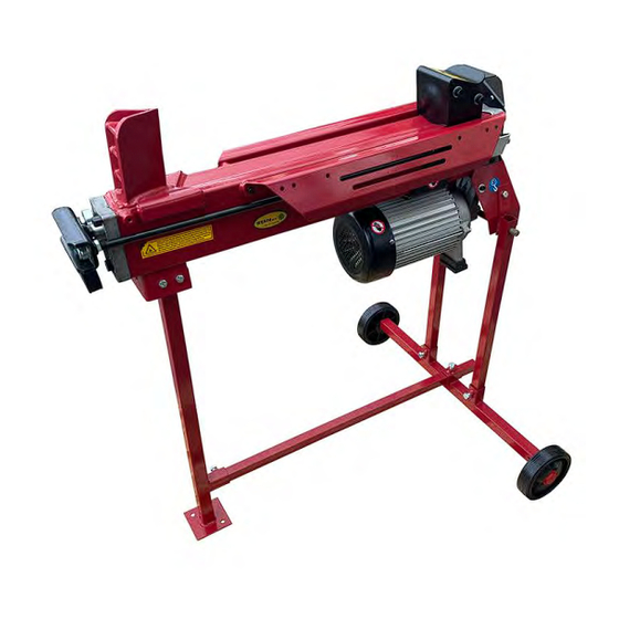
Hydraulic Log Splitter
Operator's Manual
TPLS7T
MODEL NUMBER :
SERIAL NUMBER
:
Both model number and serial number may be found on the main label.
You should record both of them in a safe place for future use.
FOR YOUR SAFETY
READ AND UNDERSTAND THE ENTIRE MANUAL BEFORE OPERATING
MACHINE
Advertisement
Table of Contents

Summary of Contents for Titan Pro TPLS7T
- Page 1 Save This Manual for Future Reference Original Instruction Hydraulic Log Splitter Operator's Manual TPLS7T MODEL NUMBER : SERIAL NUMBER Both model number and serial number may be found on the main label. You should record both of them in a safe place for future use.
-
Page 2: Table Of Contents
INTRODUCTION TABLE OF CONTENTS Introduction Your new log splitter will more than s a t i s f y y o u r e x p e c t a t i o n s . I t h a s Symbols been manufactured under stringent Safety... -
Page 3: Safety
Do not use the log splitter in wet or Dispose of the used oil in an damp areas or expose it to rain. environment-friendly way. Do not use it in areas where fumes from paint, solvents or flammable Do not use in the rain. liquids pose a potential hazard. - Page 4 Do not attempt to load the log on until AVOID ELECTRICAL SHOCK the log pusher has stopped. C h e c k t h a t t h e e l e c t r i c c i r c u i t i s adequately protected and that it Keep hands out of the way of all corresponds with the power, voltage and...
-
Page 5: Special Warnings & Instructions
Special Warnings & Instructions ● The splitting operation ● The installation and maintenance machine is designed to be activated requirements including a list of by one person. While there is the those devices e.g. two-hand control possibility that additional operators device which should be verified, could be working with the machine how frequently the verification shall... -
Page 6: Contents Supplied
CONTENTS SUPPLIED (× 2) (× 2) STEEL GUARD WIRE GUARD 1. Log Splitter Frame Steel Guard / Wire Guard 2. Transport Handle 8. Plate connector (Steel Guard only) 3. Support Strut 1 (2 pair) 9. Top Guard Plate 1 4. Support Strut 2 10. -
Page 7: Assembly
Log Tray 15. Operator's Manual 16. Hardware Bag, including 1. Mount the guard bottom plate to rear guiding plate and secure with two M6×12 socket head cap screws and M6 × 16 × 2 locknuts. M6 × 12 × 1 Loosen the socket head cap screw M6 ×... - Page 8 Loosen the cup head bolt and nut Connect the upper end of support on left side of the front leg, insert strut 1 to the log tray 2 with cross the open end of support strut 1 onto recessed pan head screw M6×12 and the bolt and then tighten the nut.
- Page 9 Steel Guard Wire Guard 1. Attach the front guard plate, left 1. Connect rear guard plates guard plate and two rear guard plates together with two M6×20 bolts, to the log tray and bottom plate with U-spacers and nuts. M6×12 bolts and nuts. 2.
-
Page 10: Know Your Machine
KNOW YOUR MACHINE Guard Wedge Log Tray Lift Handle Log Retaining Plates Pushbutton Box Switch Bleed Screw Oil Drain Bolt w/ Dipstick Work Table Log Pusher Control Lever Guard Hydraulic Control Lever Support Leg Motor Wheels Max Pressure Limiting Screw... -
Page 11: Transport
Bleed Screw TRANSPORT Before operating The log splitter is equipped with 2 the log splitter, the wheels for minor moving. To move the Bleed Screw should log splitter to the work site. be loosened by some rotations until air can go in and out of the oil tank smoothly. -
Page 12: Delivering Log Splitter To Work Site
SPLITTER OPERATION DELIVERING LOG SPLITTER TO Application Conditions WORK SITE This log splitter is a home use model. It is designed for operating under The log splitter is equipped with 2 a m b i e n t t e m p e r a t u r e s b e t w e e n wheels for minor moving. - Page 13 T r i g g e r t y p e l o c k - o u t d e v i c e i s adopted to avoid accidental Hydraulic Control Lever pushdown. To operate the Hydraulic Control Lever, draw the Trigger backward with the index finger LEFT HAND RIGHT HAND...
-
Page 14: Freeing A Jammed Log
B r e a k l o g i n t h e d i r e c t i o n o f i t s FREEING A JAMMED LOG growing grain. Do not place log across the log splitter for splitting. It may be ●... -
Page 15: Replacing Hydraulic Oil
REPLACING Do not try to knock the jammed log off. Knocking HYDRAULIC OIL a b o u t w i l l d a m a g e t h e machine or may launch the log and cause an accident. Replace the Hydraulic oil in the log splitter after every 150 hours of use. -
Page 16: Sharpening Wedge
Oil Level Use a drain pan to aid in the removal of all used oil and particles. Remove oil drain plug to drain oil from hydraulic transmission system. Examine oil for metal chips as a precaution to future problems. Read dipstick to determine the maximum and minimum of the oil level. -
Page 17: Trouble Shooting
TROUBLE SHOOTING PROBLEM PROBABLE CAUSE REMEDY SUGGESTED Refer to “Log Splitter Log is improperly positioned Operation” section for perfect log loading. The sizes or hardness of the Reduce the log sizes before log exceeds the capacity of splitting it on the log splitter. the machine Refer to “Sharpening Fails to split... -
Page 18: Wiring Diagram
WIRING DIAGRAM HYDRAULIC SYSTEM DIAGRAM... -
Page 19: Parts Schematic
PARTS SCHEMATIC... - Page 20 Parts List Description Q'ty Description Q'ty Lever Mount Nut 37 Nut M14 Cap Nut M10 38 Flat Wahser 14 Lever 39 Hexagon Thin Nut M14 Lever Knob 40 Drain Plug Guard Plate Washer Groupware 16 Customized Nut 42 Valve Sleeve Copper Gasket 10 43 O-ring 10x2 Safety Valve Bolt M8...
- Page 21 Description Q'ty Description Q'ty 94 Capacitor Bolt M5x180 95 Switch (For model 65558, 65558-6, 65558-7) 96 Switch Box Bolt M5x185 (For model 65553 only) 97 Waterproof Gasket 73 Motor Cover 98 Motor Support Left Shoe 74 Seal FB11x26x7 99 Motor Support Right Shoe 75 Nut M8 100 Pin 8X24 76 Screw M8x35...
- Page 22 STEEL GUARD WIRE GUARD...
- Page 23 Steel Guard Parts List Wire Guard Parts List Description Q'ty Description Q'ty 112 Top Guard Plate 2 112* Top Guard Plate 2 113* Screw M6x20 Screw M5x12 (For model 65558, 65558-6, 65558-7) 114* Locknut M6 Screw M5x12 115* U-Spacer (For model 65553 only) 116* Top Guard Plate 1 Locknut M5 (For model 65558, 65558-6, 65558-7)
-
Page 24: Ukca Declaration Of Conformity
UKCA DECLARATION OF CONFORMITY We Titan Pro Ltd - DT11 7FP (Importer) declare that the product: Designation: Electric Horizontal 7 Ton Log Splitter with Guard Model(s): TPLS7T Type/Serial No.: As per rating label on machine Motor Wattage: 2200 Complies with the following machinery directives: 2006/42/EC –...
Need help?
Do you have a question about the TPLS7T and is the answer not in the manual?
Questions and answers