Table of Contents
Advertisement
Quick Links
Advertisement
Table of Contents

Related Manuals for Weber mt SRV 620-II


Summary of Contents for Weber mt SRV 620-II
- Page 1 Operating and Maintenance Manual SRV 620-II 0170250 From serial no. 20034219...
-
Page 3: Table Of Contents
Table of contents Introduction Safety guidelines Graphic presentation Device description Technical data Activities prior to starting work Starting Tamping Shutting down Maintenance overview Maintenance work Operating fluids and fill levels Troubleshooting Storage Contact addresses... -
Page 4: Introduction
This operating and maintenance manual must always be available at the implementation site of the tamper. If necessary, you can obtain additional information from your authorized WEBER MT dealer, or you can obtain information from one of the contact addresses on the last page. -
Page 5: Safety Guidelines
Safety guidelines General All safety instructions must be read and complied with, as non-compliance will result in – danger to life and limb of the user, – impairments to the machine or other property. In addition to the operating manual, the accident-prevention regulations in the country where the appliance is used must be complied with. - Page 6 Operation Prior to starting work the owner of the tamper must be familiar with the work environment. The work environment includes obstacles in the work and traffic area, the bearing capacity of the ground, as well as the necessary safeguarding of the construction site in the area adjacent to public traffic; and it includes compliance with traffic regulations.
- Page 7 Maintenance and repair work Only use original Weber MT spare parts to ensure reliable and safe operation for maintenance or repair work. Adjusting tasks, maintenance tasks, and inspection tasks must be carried out on schedule as specified in this operating and maintenance manual. These activities should only be executed by instructed personnel.
- Page 8 Inspection Tampers must be inspected in accordance with appropriate implementation conditions and operating conditions, as needed; however, an inspection to ensure operationally safe status must be performed by an expert at least once a year. The results of the inspection must be recorded in writing and must be stored at least until the next inspection.
-
Page 9: Graphic Presentation
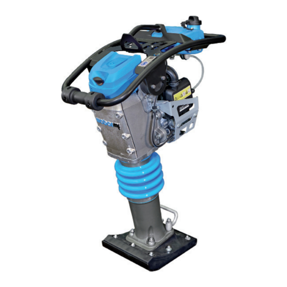
Graphic presentation Total overview SRV 620 Fuel tank Tamping system Gas lever Tamping foot Manual guidance rod Main filter Engine Secondary air filter Transport roller Handle Hearing protection (sticker) -
Page 10: Device Description
Device description The series SRV 620 tamper is used for road-building, canal construction, pipe laying and landscaping compaction tasks. Drive The tamper is powered by an air-cooled Honda gasoline engine. Force is transmitted via the centrifugal clutch directly to the tamping system. The compaction work is performed by the tamping foot. -
Page 11: Technical Data
Technical data SRV 620 Weight Operating weight CECE (in kg) Dimensions Overall length (in mm) Overall width (in mm) Height (in mm) 1035 Tamping foot width (in mm) Impact rate (/min) Stroke (in mm) 73.9 Drive Engine manufacturer Honda Type GXR 120 Performance at operating speed in accordance with ISO 3046-1 (kW) - Page 12 Note down this information so that you can recreate the rating plate should the plate be lost. 1 Description 2 Type ....................... 3 Serial no. 4 Year of construction ....................... 5 Weight 6 Rated power kW .......................
-
Page 13: Activities Prior To Starting Work
Activities prior to starting work Transport When transporting the tamper on a vehicle, secure it with suitable restraints. Loading with crane Fit the crane hook into the lifting ring (1) and lift the machine onto the desired means of transport. Only use lifting machines with a minimum bearing capacity of 100 kg. -
Page 14: Starting
Starting After horizontal transport: bring tamper into a vertical position and wait several minutes until the engine oil has collected in the lower area of the crankcase. Bring the gas lever into full-throttle (Max.) lock-in position. A valve will automatically open the fuel line. Push the choke lever (1) to the right (close). -
Page 15: Tamping
Tamping Bring the gas lever into the 1 or 2 (Max.) lock-in position. Only run machine within reach of the manual guidance rod (1). Compacting is only permissible at gas lever position 1 or 2 as there is an increase level of wear in the slip range of the centrifugal clutch. -
Page 16: Maintenance Overview
Maintenance overview Maintenance interval Maintenance point Maintenance activity After the first Engine – Change the engine oil 10 operating hours – Check valve play; adjust if necessary – Re-tighten all accessible threaded connections Every 50 operating Main air filter – Clean air filter insert, check for hours / every 6 months damage, replace if necessary Engine... -
Page 17: Maintenance Work
Maintenance work Change the engine oil Remove the oil dip stick (1). Open the drain plug (2) of the engine and drain oil. Only drain engine oil when at operating temperature. Screw in the oil drain plug (2) with new seal and top off with oil as specified. - Page 18 Clean / change secondary air filter cartridge Remove the protection (1). Remove the air filter cover (1). Remove the air filter insert (1) from the air filter enclosure / air filter cover. Clean air filter insert as specified by the engine manufacturer if there is damage or if it is extremely dirty.
- Page 19 Change the fuel line filter Pull the fuel line (2) off the fuel filter (1) on both sides. Replace the filter with a new filter element. Adjust / replace the spark plug Pull off the spark plug connector (1) and unscrew spark plug. Clean the electrode (1) of the spark plug.
- Page 20 Change the oil in the tamping system Unscrew the screw plug (1) from the fill opening. Tilt the tamper slightly and let the old oil drain into a suitable collection vessel. Set down the tamper and fill oil in as specified.
-
Page 21: Operating Fluids And Fill Levels
Operating fluids and fill levels Assembly Operating material Summer Winter Quality Engine Engine oil SAE 10 W 40 0.3 l Unleaded gasoline in accordance Gasoline 3.0 l with DIN 51607 Tamper lower part Hydraulic oil HVLPD 68 1.0 l Troubleshooting Fault Possible cause Remedy... -
Page 22: Storage
Actions to be taken before long-term storage (longer than 1 month) Entire soil compactor – Clean thoroughly – Check for leaks – If there are leaks – correct defects Fuel tank – Empty fuel and fill with clean fuel up to the lower edge of filler neck Engine –... - Page 24 facebook.com/WeberMT youtube.com/MyWeberMT Weber Maschinentechnik GmbH Im Boden 5 – 8, 10 · 57334 Bad Laasphe · Germany Phone +49 2754 398 0 · Fax +49 2754 398 101 info@webermt.de · www.webermt.de 085102153-104 / SRV 620-II_2020-02 Original operating manual...
Need help?
Do you have a question about the SRV 620-II and is the answer not in the manual?
Questions and answers