Benning DUSPOL digital plus - Two-pole voltage tester Operating Manual
- Operating manual (1 page)
Advertisement
Overview

Before using the voltage tester DUSPOL® digital plus: Please read the operating manual carefully and always observe the safety instructions!
Safety instructions
- Hold the voltage tester only by the insulated handles
![]() and
and ![]() and do not touch the contact electrodes (probe tips)
and do not touch the contact electrodes (probe tips) ![]() !
! - Immediately before use: Check the voltage tester for correct operation! The voltage tester must not be used if one or several display functions fail or if the voltage tester is not ready to operate (IEC 61243-3)!
- The voltage tester (voltage class A) must be used only within the nominal voltage range of 5 V up to AC 500 V/ 1.5 up to DC 750 V!
- Do not operate the voltage tester with the battery compartment being open!
- The voltage tester complies with protection class IP 64 and therefore can also be used under wet conditions (designed for outdoor use).
- For testing, firmly grasp the voltage tester by the handles
![]() and
and ![]() .
. - Never connect the voltage tester to voltage for longer than 30 seconds (maximum permissible operating time = 30 s)!
- The voltage tester only operates correctly within the temperature range of -10°C up to +55°C at relative air humidity of 20% up to 96%.
- Do not dismantle the voltage tester!
- Please protect the housing of the voltage tester against contamination and damages!
- Please store the voltage tester under dry conditions.
- To prevent injuries and discharge of the battery, provide the contact electrodes (probe tips) with the enclosed cover after using the voltage tester!
Attention:
After maximum load (i.e. after a measurement of 30 seconds at AC 500 V/ DC 750 V), the voltage tester must not be used for a duration of 240 seconds!
The voltage tester is marked with international electric symbols and symbols for indication and operation with the following meaning:


Functional description
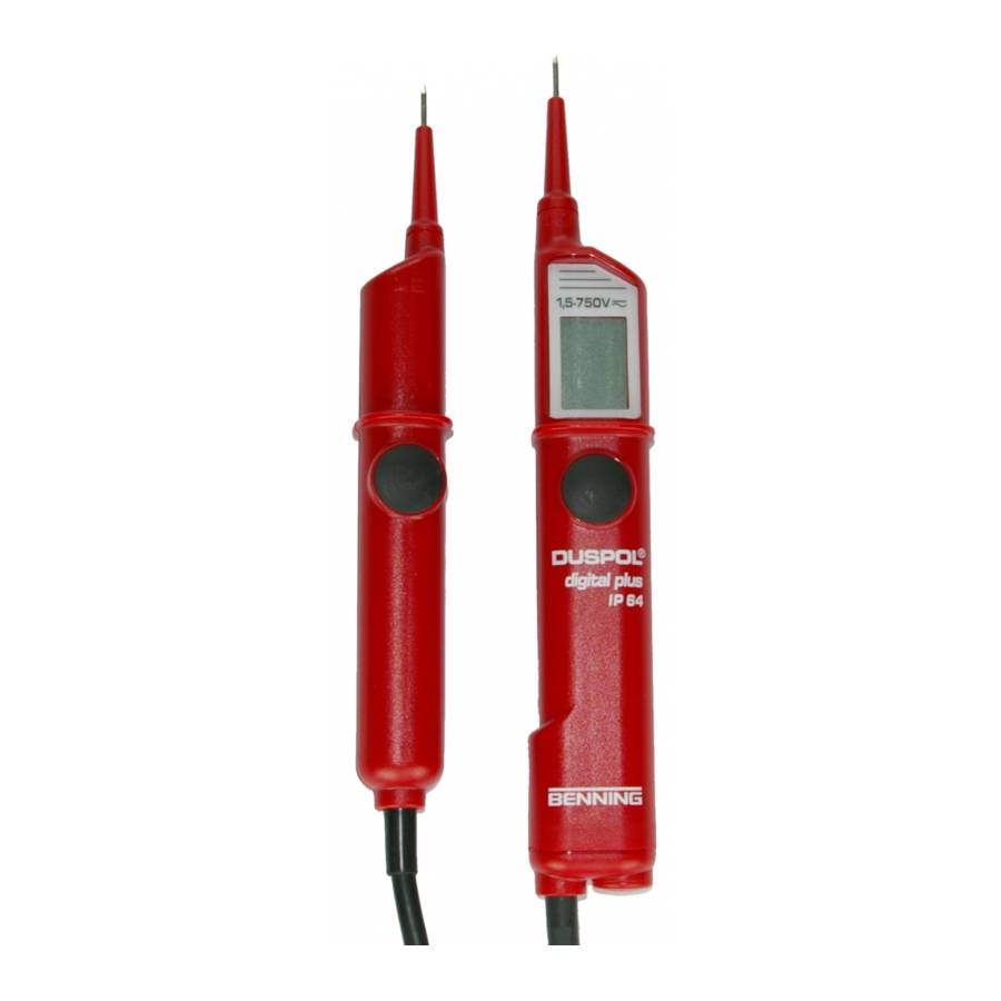
The DUSPOL® digital plus is a two-pole voltage tester according to IEC 61243-3 with digital display. As supplementary function, the voltage tester is equipped with a measuring point illumination and display illumination as well as with a phase and phase-sequence indication. For all these functions, the voltage tester requires a built-in battery (2x micro LR03/ AAA). Determining the phase of external conductors and the phase-sequence of a three-phase mains is only possible provided the neutral is earthed. The voltage tester is designed for DC and AC voltage tests within the voltage range of 5 V up to AC 500 V/ 1.5 up to DC 750 V. It can be used to perform polarity tests at DC voltage.
The voltage tester consists of the test probes L1  and L2
  and a connecting cable
  . The test probe L1 is equipped with a LC display
  . Both test probes are provided with push buttons
  . From a voltage of 6 V onwards, the voltage tester switches on automatically. For voltage tests below 6 V, the voltage tester has to be switched on by briefly pressing the push button of test probe L2 . The voltage tester only works properly with the batteries (inside test probe L1 ) being intact and inserted correctly. The display indicates voltages within the nominal voltage range of 5 V up to AC 500 V/ 1.5 up to DC 750 V. Exceeding the limiting value for low voltages (ELV, AC 50 V, DC 120 V) is additionally indicated on the display.
By pressing both push buttons, the voltage tester switches to a lower internal resistance (suppression of inductive and capacitive voltages). Furthermore, a vibrating motor (motor with a flyweight) is put under voltage. From approximately 200 V this motor is set in rotation. With the voltage increasing, the motor's speed and vibration increases as well so that additionally by means of the handle of test probe L2 the voltage value can be estimated roughly (e.g. 230/ 400 V). The duration of the test with a lower internal resistance of the device (load test) depends on the value of the voltage to be measured. To prevent excessive warming of the voltage tester, it is equipped with a thermal protection (reverse control). With this reverse control, the speed of the vibrating motor decreases as well.
The measuring point illumination can be activated by means of the push button of test probe L1 with the device being switched on. Depending on the brightness, the LCD background illumination is activated automatically.
Hold Function
If you press and hold the push button of test probe L1 during a voltage test, the last measuring value is indicated and is flashing. The voltage tester can be separated from the unit under test and the measuring value can be read (DATA-HOLD). The value can be deleted by releasing the push button.
Display field
The display field consist of an LC display. This display indicates the exceeding of the upper limiting value for low voltages (ELV)  , the phase, the phase-sequence
  and
and  , the exact voltage value
  , the polarity at DC voltage
  and
and  as well as a symbol for weak batteries
  . The measuring range for continuous voltage measurement is set automatically. Up to 80 V, the value is indicated with a decimal place. For higher values, the decimal place is not indicated.
Functional check
- The voltage tester must be used only within the nominal voltage range of 5 V up to AC 500 V/ 1.5 up to DC 750 V!
- Never connect the voltage tester to voltage for longer than 30 seconds (maximum permissible operating time = 30 s)!
- Check the voltage tester for correct function immediately before use!
- Activation of the testing device (self-test),
- switch the voltage tester on by means of the push button of test probe L2
![]() and hold the push button
and hold the push button - all segments must appear (test of the LC display).
- after approx. 2 seconds, a voltage value > 1 V is indicated (test of the measuring system)
- then, short-circuit the contact electrodes
![]() of the two test probes, the indicated voltage value must be 0.0 V (test of the cable connection)
of the two test probes, the indicated voltage value must be 0.0 V (test of the cable connection) - after approx. 1 second, the measuring point and LCD illumination is switched on (test of cable connection and illumination)
- switch the voltage tester on by means of the push button of test probe L2
- Test all functions by means of known voltage sources.
- For DC voltage tests use e.g. a car battery.
- For AC voltage tests use e.g. a 230 V socket.
- If necessary, replace the batteries.
Do not use the voltage tester unless all functions are operating correctly!
How to test AC voltages
- The voltage tester must be used only within the nominal voltage range of 5 V up to AC 500 V!
- Never connect the voltage tester to voltage for longer than 30 seconds (maximum permissible operating time = 30 s)!
- Firmly grasp the insulated handles
![]() and
and ![]() of the test probes L1 and L2.
of the test probes L1 and L2. - Place the contact electrodes
![]() of the test probes L1
of the test probes L1 ![]() and L2
and L2 ![]() against the relevant points of the unit under test.
against the relevant points of the unit under test. - If a measuring voltage is present (5 V), the voltage tester switches on automatically and indicates the voltage value on the display.
- The LC display
![]() indicates the voltage value by means of the three-digit indication
indicates the voltage value by means of the three-digit indication ![]() .
. - When pressing both push buttons
![]() and from an applied voltage of approx. 200 V onwards, a vibrating motor is put in rotation inside the test probe L2
and from an applied voltage of approx. 200 V onwards, a vibrating motor is put in rotation inside the test probe L2 ![]() . With the voltage increasing, the speed of this motor is increasing as well.
. With the voltage increasing, the speed of this motor is increasing as well.
Please make sure that you touch the voltage tester at the insulated handles of test probes L1 and L2 only! Do not cover the display and do not touch the contact electrodes!
At AC voltage from 5 V onwards, the display indicates the „plus" and „minus" symbol and . Furthermore, the three-digit indication indicates the measuring value (up to approx. 80 V with decimal place!).
Note:
The reading of the LC display might be impaired due to unfavorable light conditions.
How to test the phase at AC voltage
- The voltage tester must be used only within the nominal voltage range of 5 V up to AC 500 V!
- The phase test is possible in the earthed mains from 230 V onwards!
- Firmly grasp the two handles
![]() and
and ![]() of the test probes L1 and L2 (leakage current for phase test via handle L2
of the test probes L1 and L2 (leakage current for phase test via handle L2 ![]() !).
!). - Switch the voltage tester on by briefly pressing the push button
![]() of test probe L2
of test probe L2 ![]() (stays switched on for approx. 10 seconds). When the device is switched on, the display indicates „0.0"!
(stays switched on for approx. 10 seconds). When the device is switched on, the display indicates „0.0"! - Place the contact electrode
![]() of test probe L1
of test probe L1 ![]() against the relevant point of the unit under test.
against the relevant point of the unit under test. - Never connect the voltage tester to voltage for longer than 30 seconds (maximum permissible operating time = 30 s)!
Never touch the contact electrode of test probe L2 during the single-pole test (phase test)!
If the „ "-symbol appears in the upper part of the LC display , the tester is in contact with the live phase of an AC voltage on this point of the unit under test.
Note:
The reading of the LC display might be impaired due to unfavorable light conditions, protective clothing or in insulated locations.
How to test DC voltages
- The voltage tester must be used only within the nominal voltage range of 1.5 V up to DC 750 V!
- Never connect the voltage tester to voltage for longer than 30 seconds (maximum permissible operating time = 30 s)!
- Firmly grasp the insulated handles
![]() and
and ![]() of the test probes L1 and L2.
of the test probes L1 and L2. - Place the contact electrodes
![]() of the test p robes L1
of the test p robes L1 ![]() and L2
and L2 ![]() against the relevant points of the unit under test.
against the relevant points of the unit under test. - With an applied voltage of at least 6 V, the voltage tester switches on automatically and the display indicates the voltage value.
- For voltages tests below 6 V, the voltage tester has to be switched on by briefly pressing the push button
![]() of test probe L2
of test probe L2 ![]() .
. - The LC display
![]() indicates the voltage value by means of the three-digit indication
indicates the voltage value by means of the three-digit indication ![]() .
. - When pressing both push buttons
![]() and from an applied voltage of approx. 200 V onwards, a vibrating motor is put in rotation inside the test probe L2
and from an applied voltage of approx. 200 V onwards, a vibrating motor is put in rotation inside the test probe L2 ![]() . With the voltage increasing, the speed of this motor is increasing as well.
. With the voltage increasing, the speed of this motor is increasing as well.
Please make sure that you touch the voltage tester at the insulated handles of test probes L1 and L2 only! Do not cover the display and do not touch the contact electrodes!
How to test the polarity at DC voltage
- The voltage tester must be used only within the nominal voltage range of 1.5 V up to DC 750 V!
- Never connect the voltage tester to voltage for longer than 30 seconds (maximum permissible operating time = 30 s)!
- Firmly grasp the insulated handles
![]() and
and ![]() of the test probes L1 and L2.
of the test probes L1 and L2. - Place the contact electrodes
![]() of the test probes L1
of the test probes L1 ![]() and L2
and L2 ![]() against the relevant points of the unit under test.
against the relevant points of the unit under test. - With an applied voltage of at least 6 V, the voltage tester switches on automatically and the display indicates the voltage value.
- For voltages tests below 6 V, the voltage tester has to be switched on by briefly pressing the push button
![]() of test probe L2
of test probe L2 ![]() .
. - The polarity of the applied DC voltage is indicated by means of a +
![]() or a – symbol
or a – symbol ![]() . Here, the indicated pole is the pole measures by the indicating handle
. Here, the indicated pole is the pole measures by the indicating handle ![]() .
.
Please make sure that you touch the voltage tester at the insulated handles of test probes L1 and L2 only! Do not cover the display and do not touch the contact electrodes!
How to test the phase sequence of a three-phase mains
- The voltage tester must be used only within the nominal voltage range of 5 V up to AC 500 V!
- The phase-sequence test is possible from 230 V AC voltage (phase against phase) onwards in a earthed three-phase mains.
- Firmly grasp the insulated handles
![]() and
and ![]() of the test probes L1 and L2.
of the test probes L1 and L2. - Place the contact electrodes
![]() of the test probes L1
of the test probes L1 ![]() and L2
and L2 ![]() against the relevant points of the unit under test.
against the relevant points of the unit under test. - With an applied voltage of at least 5 V, the voltage tester switches on automatically and the display indicates the voltage value.
- The three-digit display has to indicate the voltage of the external conductor.
- Never connect the voltage tester to voltage for longer than 30 seconds (maximum permissible operating time = 30 s)!
When contacting the two contact electrodes  with two phases of a three-phase mains connected in clockwise rotation, the LC display indicates the symbol "
 " (phase-sequence clockwise) . If for two phases the rotation is counter-clockwise, the LC display indicates the symbol "
 " (phase-sequence counter-clockwise) .
The phase-sequence test always requires a counter-test! For this purpose, the measurement has to be performed again with reversed contact electrodes . During the counter-test, the LC display must indicate the opposite phase-sequence. If in both cases, the LC display indicates a clockwise phase-sequence, the earthing is too weak!
Note:
The reading of the LC display might be impaired due to unfavorable light conditions, protective clothing or in insulated locations.
Battery replacement
Do not set the voltage tester under voltage with the battery compartment being open!
The energy supply of the DUSPOL® digital plus is done by means of two built-in micro batteries (LR03/ AAA). Battery replacement is necessary as soon as the display shows the battery symbol " " (weak battery) . The symbol appears in case the battery voltage is below 2.75 V. If the battery voltage drops below a value of approx. 2.5 V, the battery symbol is flashing.
Indicating the battery voltage
Switch the voltage tester on by briefly pressing the push button of test probe L2 . After approx. 10 seconds, the value of the battery voltage is indicated for 1 second. (Example:  )
)
How to replace the batteries:
Take a screw driver and open the battery compartment (next to the cable outlet) by a 1⁄4-turn in direction of the arrow (counter-clockwise). The slot is now vertical and the battery compartment with the batteries can be removed.
Remove the discharged batteries from the battery compartment. Insert the new batteries with correct polarity (see marking) into the battery compartment. Put the battery compartment with the batteries back onto the handle and lock it by 1⁄4-turn in clockwise direction (slot must be horizontal and the marking points are opposite!). Make sure not to damage the O ring. If necessary, it has to be replaced.
Battery disposal:
Do not dispose of batteries with the household garbage. You as a consumer are legally obliged to return used batteries. You can return used batteries to public collection facilities in your community area or return them to any retail outlet selling similar batteries. Avoid using batteries containing dangerous substances!
General maintenance
Clean the exterior of the housing with a clean dry cloth (exception: special cleansing cloths). Do not use solvents and/or abrasives to clean the voltage tester. Make sure not to contaminate the battery compartment and the battery contacts with leaking battery electrolyte. Should such electrolyte contamination or white deposits occur near the battery or the battery housing, these must also be removed with a dry cloth. In case of wear or damaging of the O ring of the battery compartment, the voltage tester does not comply with the indicated protection class anymore (protection against dust and water). In this case, the O ring must be replaced.
The O ring can be ordered under the BENNING piece number 772871. Moisten a new O ring with Vaseline or talcum so that the battery compartment can be locked and unlocked easily.
Technical data
- Guideline for two-pole voltage testers: IEC 61243-3
- Protection class: IP 64, IEC 60529 (DIN 40050), also for outdoor use!
- Nominal voltage range (voltage class A): 5 V up to AC 500 V/ 1.5 up to DC 750 V
- Internal resistance, measuring circuit: 440 kΩ, parallel 4.7 nF (2.35 nF)
- Internal resistance, load circuit – both push buttons actuated!: approx. 3.7 kΩ...(150 kΩ)
- Current consumption, measuring circuit: max. In 3.5 mA (500 V) AC/ 1.7 mA (750 V) DC
- Current consumption, load circuit - both push buttons actuated!: Is 0.2 A (750 V)
- Polarity indication: LCD symbol +; - (indicating handle = positive polarity)
- Voltage indication, continuous 1.5 or 5 - 750 V, indicating height 7 mm
- Voltage range I: up to approx. 80.0 V (88.8)
- Voltage range II from approx. 80 V (888) onwards - max. indicating errors: > 5 - 750 V ± 2% of Voltage range (I-II) at frequency 20 - 150 Hz sinusoidal or DC ELV Un – 15 %
- Nominal frequency range f: 0 up to 150 Hz
Phase and phase-sequence indication 50/ 60 Hz - Phase and phase-sequence indication: ≥ Un 230 V
- Vibrating motor, starting: ≥ Un 230 V
- max. permissible operating time: ED = 30 s (max. 30 seconds), 240 s pause
- Device switch-on (automatic) at measuring voltage: ≥ 6 V
- Device switch-on (manual): by means of push button L2
![]() (measuring voltage ≤ 6 V)
(measuring voltage ≤ 6 V) - Duration of device switch-on: up to 10 seconds, if no measuring voltage is present
- Measuring point illumination (in 30 cm): 10 Lux
- Current consumption, voltage test: 3.1 mA
- Current consumption, measuring point illumination: 12 mA
- Current consumption, display illumination: 10 mA
- Built-in testing function: activation by push button L2
![]() and short-circuit of the contact electrodes
and short-circuit of the contact electrodes - Battery: 2 x micro, LR03/ AAA (3 V)
- Weight: approx. 200 g
- Connecting cable length: approx. 900 mm
- Operating and storing temperature range: -10°C up to +55°C (climate category N)
- Relative air humidity: 20% up to 96% (climate category N)
- Reverse control times (thermal protection):
voltage time 230 V 30 s 400 V 9 s 750 V 2 s
Attention!
The voltage tester cannot be operated with the batteries being empty! Remove the batteries from the device at a longer storage!
BENNING Elektrotechnik & Elektronik GmbH & Co. KG
Münsterstraße 135 - 137 • D - 46397 Bocholt
Telefon ++49 (0) 2871 - 93 - 0 • Fax ++49 (0) 2871 - 93 - 429
www.benning.de • E-Mail: duspol@benning.de

Documents / Resources
References
Download manual
Here you can download full pdf version of manual, it may contain additional safety instructions, warranty information, FCC rules, etc.
Download Benning DUSPOL digital plus - Two-pole voltage tester Operating Manual
Advertisement


Need help?
Do you have a question about the DUSPOL digital plus and is the answer not in the manual?
Questions and answers