Table of Contents
Advertisement
Quick Links
www.ti.com
EVM User's Guide: LMG2100 LMG2100EVM
LMG2100EVM-078 Evaluation Module
Description
The LMG2100 evaluation module is a compact, easy-
to-use power stage with an external PWM signal.
The board can be configured as a buck converter,
boost converter, or other converter topology using
a half bridge. Because this is an open-loop board
with an external PWM signal, do not use to evaluate
transient response. The device can be used to
evaluate the performance of the LMG2100 as a
hard-switched converter to sample measurements
such as efficiency, switching speed and dv/dt (slew
rate). The EVM features a LMG2100 half-bridge
power module with two 100 V, 4.4-mΩ GaN FETs
driven by 80-V GaN FET half-bridge gate driver. The
module can deliver up to 20 A of current if the
application includes adequate thermal management
(monitor case temperature and verify adequate airflow
is present if required). The thermal management
considerations include forced air, heat sink, and lower
operating frequency to minimize the power dissipation
in the module.
SNVU863 – JULY 2023
Submit Document Feedback
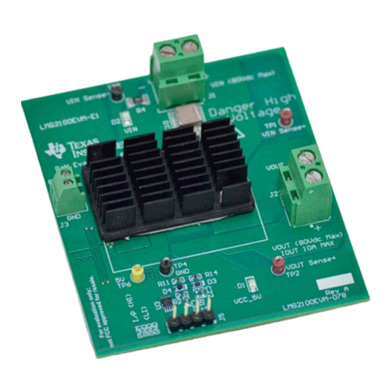
LMG2100EVM-078 Evaluation Module with Heat Sink
Copyright © 2023 Texas Instruments Incorporated
Features
•
Input voltage operates up to 80 V DC
•
Integrated 100-V, 4.4-mΩ GaN FETs with driver
•
Open loop control with single or dual PWM signals
•
Single-input, onboard for PWM signal with 8-ns
dead time
•
Configurable onboard dead-time adjustment by
simple resistance change
•
Onboard LDO for generating 5-V VCC supply from
an unregulated supply between 5.5 V and 10 V
•
Kelvin sense capability for efficiency
measurements for input and output voltage
•
Slew rate adjustment using series resistors along
with C
and C
boot
vcc
Applications
•
High-speed synchronous buck/boost converters
•
Solar power
optimizer,
•
Class D amplifiers for audio
•
48-V point-of-load converters for industrial
•
Motor drives
•
Power tools
•
Telecom and server power
LMG2100EVM-078 Evaluation Module
Description
Micro-inverter
1
Advertisement
Table of Contents

Related Manuals for Texas Instruments LMG2100


Summary of Contents for Texas Instruments LMG2100
- Page 1 Description EVM User's Guide: LMG2100 LMG2100EVM LMG2100EVM-078 Evaluation Module Description Features The LMG2100 evaluation module is a compact, easy- • Input voltage operates up to 80 V DC to-use power stage with an external PWM signal. • Integrated 100-V, 4.4-mΩ GaN FETs with driver The board can be configured as a buck converter, •...
-
Page 2: Kit Contents
The LMG2100 is available in a 5.5 mm x 4.5 mm x 0.89 mm lead-free QFN package with exposed die on the top side for cooling. Power pins of the device are optimized to accommodate easy PCB layout to achieve smaller power loop. - Page 3 Hardware 2 Hardware General Texas Instruments High Voltage Evaluation (TI HV EVM) User Safety Guidelines WARNING Always follow TI's set-up and application instructions, including use of all interface components within their recommended electrical rated voltage and power limits. Always use electrical safety precautions to help ensure your personal safety and those working around you.
-
Page 4: Test Points
There is the bias supply EXTVCC (between 5.5 V and 10 V) for the LMG2100 driver. This driver supply is regulated to 5 V by the series LDO U2 (LP3869). This regulation verifies that the bias supply for the LMG2100 is accurate and is not exceeded beyond the gate voltage specifications. -
Page 5: Power-Up Procedure
LMG2100 half bridge. The output load is connected to the J2 connector. The positive and negative sense signals are TP2 and TP3, respectively. -
Page 6: Power-Down Procedure
2. Next, turn off the input supply. 3. The PWM signal must be turned off next. 4. Finally, turn off the driver bias supply. LMG2100EVM-078 Evaluation Module SNVU863 – JULY 2023 Submit Document Feedback Copyright © 2023 Texas Instruments Incorporated... -
Page 7: Assembly Guidelines
Hardware 2.4 Assembly Guidelines Please follow the recommended assembly guidelines for the LMG2100 samples: • Use low temperature solder paste (like Sn42-Bi58) whose melting temperature is around 130℃-140℃. • Soldering using bottom side heating: – Recommended for thinner board (less than or equal to four layers) with no components directly underneath the device. -
Page 8: Electrical Performance Specifications
Figure 3-2 show the top and bottom views of the LMG21EVM-078, respectively. Figure 3-1. LMG2100EVM-078 Board (Top View) Figure 3-2. LMG2100EVM-078 Board (Bottom View) LMG2100EVM-078 Evaluation Module SNVU863 – JULY 2023 Submit Document Feedback Copyright © 2023 Texas Instruments Incorporated... - Page 9 High voltages that can cause injury exist on this evaluation module (EVM). Please verify all safety procedures are followed when working on this EVM. Never leave a powered EVM unattended. SNVU863 – JULY 2023 LMG2100EVM-078 Evaluation Module Submit Document Feedback Copyright © 2023 Texas Instruments Incorporated...
- Page 10 Figure 3-6. Zoom in of the SW Node Showing the Dead Time of 8 ns (Buck Converter Loaded With 15 A) Note Visit the E2E forum Gallium Nitride Solutions for more information regarding LMG2100 or LMG2100 hard-switched EVM. LMG2100EVM-078 Evaluation Module SNVU863 – JULY 2023 Submit Document Feedback Copyright ©...
- Page 11 Hardware Design Files 4 Hardware Design Files SNVU863 – JULY 2023 LMG2100EVM-078 Evaluation Module Submit Document Feedback Copyright © 2023 Texas Instruments Incorporated...
- Page 12 Green PGND SN74LVC3G14DCUR PGND SDM03U40-7 Connector for PWM IN LO_SIGNAL 10.0k 100pF SN74LVC3G14DCUR SDM03U40-7 HI_SIGNAL 100pF SN74LVC3G14DCUR Dead-Time Generating Circuit Figure 4-1. LMG2100EVM-078 Schematic LMG2100EVM-078 Evaluation Module SNVU863 – JULY 2023 Submit Document Feedback Copyright © 2023 Texas Instruments Incorporated...
-
Page 13: Pcb Layouts
Hardware Design Files 4.2 PCB Layouts Figure 4-2. Top Layer of the PCB Figure 4-3. Mid Layer-1 showing return path for power loop SNVU863 – JULY 2023 LMG2100EVM-078 Evaluation Module Submit Document Feedback Copyright © 2023 Texas Instruments Incorporated... - Page 14 Hardware Design Files www.ti.com Figure 4-4. Mid Layer-2 Figure 4-5. Bottom Layer LMG2100EVM-078 Evaluation Module SNVU863 – JULY 2023 Submit Document Feedback Copyright © 2023 Texas Instruments Incorporated...
-
Page 15: Bill Of Materials
Inductor, Shielded, Composite, 10 x 10 x 11.3mm XAL1010-472MED Coilcraft 4.7 µH, 25.4 A, 0.0057 ohm, 1.0k RES, 1.0k ohm, 5%, 0.1W, 0603 CRCW06031K00JNEA Vishay-Dale 0603 SNVU863 – JULY 2023 LMG2100EVM-078 Evaluation Module Submit Document Feedback Copyright © 2023 Texas Instruments Incorporated... -
Page 16: Additional Information
Unless otherwise noted, all parts can be substituted with equivalents. 5 Additional Information 5.1 Trademarks All trademarks are the property of their respective owners. LMG2100EVM-078 Evaluation Module SNVU863 – JULY 2023 Submit Document Feedback Copyright © 2023 Texas Instruments Incorporated... - Page 17 STANDARD TERMS FOR EVALUATION MODULES Delivery: TI delivers TI evaluation boards, kits, or modules, including any accompanying demonstration software, components, and/or documentation which may be provided together or separately (collectively, an “EVM” or “EVMs”) to the User (“User”) in accordance with the terms set forth herein.
- Page 18 www.ti.com Regulatory Notices: 3.1 United States 3.1.1 Notice applicable to EVMs not FCC-Approved: FCC NOTICE: This kit is designed to allow product developers to evaluate electronic components, circuitry, or software associated with the kit to determine whether to incorporate such items in a finished product and software developers to write software applications for use with the end product.
- Page 19 www.ti.com Concernant les EVMs avec antennes détachables Conformément à la réglementation d'Industrie Canada, le présent émetteur radio peut fonctionner avec une antenne d'un type et d'un gain maximal (ou inférieur) approuvé pour l'émetteur par Industrie Canada. Dans le but de réduire les risques de brouillage radioélectrique à...
- Page 20 www.ti.com EVM Use Restrictions and Warnings: 4.1 EVMS ARE NOT FOR USE IN FUNCTIONAL SAFETY AND/OR SAFETY CRITICAL EVALUATIONS, INCLUDING BUT NOT LIMITED TO EVALUATIONS OF LIFE SUPPORT APPLICATIONS. 4.2 User must read and apply the user guide and other available documentation provided by TI regarding the EVM prior to handling or using the EVM, including without limitation any warning or restriction notices.
- Page 21 Notwithstanding the foregoing, any judgment may be enforced in any United States or foreign court, and TI may seek injunctive relief in any United States or foreign court. Mailing Address: Texas Instruments, Post Office Box 655303, Dallas, Texas 75265 Copyright © 2023, Texas Instruments Incorporated...
- Page 22 TI products. TI’s provision of these resources does not expand or otherwise alter TI’s applicable warranties or warranty disclaimers for TI products. TI objects to and rejects any additional or different terms you may have proposed. IMPORTANT NOTICE Mailing Address: Texas Instruments, Post Office Box 655303, Dallas, Texas 75265 Copyright © 2023, Texas Instruments Incorporated...
Need help?
Do you have a question about the LMG2100 and is the answer not in the manual?
Questions and answers