Table of Contents
Advertisement
Quick Links
Advertisement
Table of Contents

Related Manuals for Zeiss i.Profiler plus


Summary of Contents for Zeiss i.Profiler plus
- Page 1 i.Profiler plus Instructions for use – Part 1 Version 1.5...
- Page 2 Carl Zeiss Vision does not endorse or recommend these products, unless explicitly stated otherwise. Carl Zeiss Vision assumes no liability for the performance or use of these products. TRADEMARK is a trademark or registered trademark of LEGAL ENTITY TRADEMARK OWNER.THIRD PARTY TRADEMARK is a trademark or registered...
-
Page 3: Table Of Contents
Contents Contents ...........................3 Information on this Instructions for use – Part 1 .................5 Purpose and availability of documentation ................5 Explanation of symbols ......................6 Scope of delivery ........................5 Country-specific information and exterior labeling ..............6 Manufacturer classification/declaration ..................6 Intended use .........................6 Normal Use / Indication ......................6 Proper use..........................7 Target Customers ........................7 User profile I: Measurements with the i.Profiler... - Page 4 Problems with the internal printer ..................45 Problems with movable optical measuring head ..............45 Warnings regarding measurement quality ................45 Warnings due to wrong operator entry ................46 Other Warnings due to hardware or software failure ............46 Safety Warnings regarding unwanted behavior ..............46 Measurement problems .......................
-
Page 5: Contents
Information on this Instructions for use – Part 1 Information on this Instructions for use – Part 1 Purpose and availability of documentation This Instruction for use - Part 1 and the associated Instruction for use - Part 2 explain the safety measures, function, use, performance parameters, care and maintenance measures required for the i.Profiler plus . -
Page 6: Explanation Of Symbols
Information on this Instructions for use – Part 1 Explanation of symbols The symbols used in these Instructions for use – Part 1 notify you of important safety information and may include warnings of potential health hazards or death or may provide useful tips. When you see these symbols, please read the provided information carefully and observe the safety notices and information specifically designated in these Instructions for use –... -
Page 7: Scope Of Delivery
• Printer paper roll • Stylus for use on the touch screen • Test eye device • Dust protection cover A current, complete list of accessories is available from Carl Zeiss Vision GmbH and authorized service partners. EN 20_070_0009I v1.5... -
Page 8: Country-Specific Information And Exterior Labeling
Country-specific information and exterior labeling Country-specific information and exterior labeling Manufacturer classification/declaration WARNING - GENERAL HAZARD This device may only be set up, operated and used according to its intended purpose and in accordance with country-specific provisions, occupational protection and accident prevention regulations. Further information on classification is provided in the section Technical data. -
Page 9: Proper Use
Country-specific information and exterior labeling Proper use CAUTION - HAZARD DUE TO INCORRECT OPERATION The device may only be installed, operated, used and maintained by persons with the necessary training or knowledge and experience. Please also observe the national qualification guidelines applicable in your country. - Page 10 Country-specific information and exterior labeling User profile IA: Optometry/ophthalmology assistant The user (e.g. trainee, salesperson) should have the experience described under user i.Profiler plus the following skills: • Handling of standard test records and measurement results in optics/ optometry such as refraction values (sphere, cylinder, axis), higher- order aberrations (Zernike polynomials), ophthalmometer readings (corneal radii) and corneal topography data (axial, local and height representation, etc.)
-
Page 11: User Profile Ii: Analysis Of Measured Data
Country-specific information and exterior labeling User profile IB: Clinical/practice assistant In addition to the experience described in user profiles I and IA, the user (e.g., doctor's assistant, nurse) should have knowledge of pathological factors which influence measurement quality, as listed below: •... -
Page 12: Disposing Of The Product
Country-specific information and exterior labeling Disposing of the product CAUTION - ENVIRONMENTAL CONTAMINATION HAZARD The packaging material should be stored in case of relocation or repair. If you want to dispose of the packaging material, recycle it via a recognized collection system. The device contains electronic components. -
Page 13: Exterior Labeling
Country-specific information and exterior labeling Exterior labeling 1 i.Profiler plus type plate 2 Notification sign & Date of manufacture Fig. 1: Type plate on i.Profiler plus EN 20_070_0009I v1.5... - Page 14 Country-specific information and exterior labeling Labelling refers to Material Number (REF): 2358-727 i.Profiler plus type plate Type B applied part EU conformity slip with ID number for the notified body Manufacturer Fuse Date of manufacture Alternating current Catalog number/part number Serial number Disposal notification for the...
- Page 15 Country-specific information and exterior labeling Labelling refers to Material Number (REF): 1005-825 i.Profiler plus type plate Type B applied part EU conformity slip with ID number for the notified body Manufacturer Fuse Alternating current Catalog number/part number Serial number Disposal notification for the EU TÜV Rheinland...
-
Page 16: Performance Specification
Performance specification Performance specification Functional description The i.Profiler offers two basic measurement options: plus • Precision wavefront measurement with Shack-Hartmann technology • Placido disc-based corneal topography with central and peripheral keratometry Wavefront measurement 1 Eye 2 Beam splitter 3 Microlens array 4 Camera Fig. -
Page 17: Fig. 3: Image Of The Points Of Light On The Chip Of The Camera (A) And Image Of The Reconstructed Wavefront Map (B) Over The Entire Exit Pupil
Performance specification Measurement of wavefront aberrations is based on the technology of a Shack-Hartmann sensor. Its function is illustrated in a simplified manner in Fig. 2. An infrared laser beam creates a point of light on the retina of the eye. -
Page 18: Topography Measurement
Performance specification The wavefront map is colored uniformly for an emmetropic eye without aberrations. If an eye has refractive errors, these are shown as color coded in the wavefront map. Short sightedness (myopia) and far sightedness (hyperopia) are expressed in wavefront maps showing spherical caps curved inward or outward. -
Page 19: Fig. 5: The Image Of The Rings Of The Placido Disc On The Camera For A Normal Cornea
Performance specification The Placido disc has ring-shaped, diffuse transparent openings that ensure the rings are projected evenly on the eye. The eye, positioned in front of the Placido disc, reflects the ring pattern of the Placido disc like a convex mirror. The reflections on the corneal surface of the eye are recorded by a video camera (CCD camera) behind the Placido disc. -
Page 20: Service Life
Performance specification Service life WARNING - GENERAL HAZARD The development, manufacturing and maintenance of the device and associated hazards are based on an expected service life of eight years. Modifications may only be made by professional technician trained by the manufacturer. The device may only be serviced and repaired by the manufacturer. -
Page 21: Device Description
Device description Device description 1 Optical measuring head 2 LCD touch screen (swiveling) 3 On/off switch (Standby) 4 Stylus Fig. 6: i.Profiler plus , operating side view Fig. 6 and Fig. 7 show the i.Profiler from the operating and customer plus sides. -
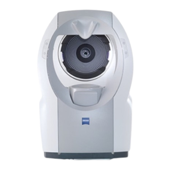
Page 22: Fig. 7: I.profiler Plus , Customer Side View
Device description 1 Base device with computer and electronics 2 Motorized chin rest 3 Double-sided, dual button control for the chin rest 4 Measurement optic aperture 5 Forehead rest Fig. 7: i.Profiler , customer side view plus EN 20_070_0009I v1.5... -
Page 23: Installation
Installation Installation WARNING - GENERAL HAZARD The device may not be stored or operated outside of the prescribed ambient conditions (see Technical data on page 51). The device must be set up so that the power cable can be unplugged immediately and without tools from the power network. - Page 24 Installation CAUTION - HAZARD DUE TO FALLING PARTS When using a suitable table, ensure that the selected combination of table and device is stable up to a tilt of 10°. In addition, the table must be designed to handle 4x the mass of the set-up device configuration. If mobile table stands are used, these must have a locking brake.
-
Page 25: Set-Up
Installation Set-up CAUTION - PROPERTY DAMAGE To move the device, always use two persons to lift the device by its recessed grips (1, Fig. 8) on the bottom and not by the display! Transport the device on a movable base with a brake if possible. Avoid shocks during transportation, since the device contains components that are sensitive to shocks. -
Page 26: Electrical Installation
Installation Electrical installation • Connect any optional accessories. • Connect the network cable. 1 LAN ports with 4 kV cut-off voltage (2) 2 USB ports (3) 3 VGA port for monitor 4 Serial interface RS232 5 Fuse compartment 6 Power switch on (I)/Off (0) 7 Connection for network cable 8 Installed printer (paper printing) 9 USB port... -
Page 27: Touch Screen Calibration
Installation CAUTION - HAZARD DUE TO INCORRECT OPERATION Only install software approved by Carl Zeiss Vision on this device. The device may only be connected to networks protected from public networks (internet) by state-of-the-art firewalls! Touch screen calibration ● After starting the i.Profiler... -
Page 28: Connecting The I.profiler
Installation Alternatively, you can proceed as follows: • Click the pictogram on the right side of the taskbar. • Select Graphics Options from the menu bar. • Under Output To, select “Intel ® Dual Display Clone" and then "Notebook + Monitor.” •... -
Page 29: Connecting The I.profiler
Installation Connecting the i.Profiler plus to an existing local network ● Connect the i.Profiler plus to the practice network (LAN) using a network cable. ● Switch on the i.Profiler plus . After starting the i.Profiler plus , use the Close application button in the Power down window to switch to the Windows desktop (Administrator rights required). -
Page 30: Printer Installation For The I.profiler Plus
Installation Printer installation for the i.Profiler plus WARNING - DANGER OF ELECTRICAL SHOCK The printer must be set up out of the customer’s range (1.5 m from the customer's seat on the device) and connected to a separate outlet. The operator may not touch the printer and customer at the same time. -
Page 31: Connect Printer Directly To The I.profiler
Installation Connect printer directly to the i.Profiler (peer to peer) plus Connect the network printer or printer server with the i.Profiler plus using a so-called crossover cable (crossed network cable) or an uncrossed cable with a crossover adapter. ● Switch on the i.Profiler plus and printer or printer server. -
Page 32: Connect Printer Via An Existing Network
Installation Connect printer via an existing network The responsible administrator of your local network must first set up the network printer or printer server in the network. Please see the network printer or print server manual for the process for configuring the printer. -
Page 33: Configuring A Network Attached Storage Device
Installation Configuring a network attached storage device WARNING - DANGER OF ELECTRICAL SHOCK If the NAS device is not supplied with power via an isolating transformer, it must be set up at least 1.5 m away from the customer so that the customer is not able to touch the device during the examination with any part of their body. -
Page 34: Requirements For The Nas Device
Installation Requirements for the NAS device The NAS device must offer the following performance features to ensure proper safety and acceptable performance when using the i.Profiler plus • Support 100BaseT or 1000BaseT Ethernet. For safety reasons, a USB connection is not permitted with the i.Profiler plus •... -
Page 35: Installing The Nas Device
. Often, a light on the front of the NAS device changes color to indicate that initialization is complete. Further information is provided in the manufacturer's operating instructions. Installing the Carl Zeiss Meditec (CZM)-NAS device ● Switch on the i.Profiler . After starting the device, click the Close... - Page 36 ● Create a local directory on the NAS device. ● Create a user account on the NAS device. We recommend using the username “Zeiss” and the password “November171846.” ● If there is a Workgroup, we recommend naming it “CZM.” ● Approve reading and writing rights to the locally created directory o n the NAS device for the previously created user account.
- Page 37 Installation Connect NAS device via an existing network ● When the i.Profiler plus and NAS device are switched off, connect the NAS device to the practice network (LAN) in which the i.Profiler plus is located using a network cable. Complete information on installing the NAS device is provided in the instructions enclosed with the NAS device.
-
Page 38: Daily Commissioning
If an instrument table is used, the device receives electrical power through the table. If a table which has not been authorized by Carl Zeiss is used, the user bears sole responsibility for the electrical safety of the device. • The power plug must be inserted into an outlet with a proper protective conductor connection. -
Page 39: Switch On
Installation Switch on ● To switch on the device, activate the power switch (6, Fig. 9) and then the Standby button (3, Fig. 6). The i.Profiler plus software will be started automatically and the Customer window will open. ● After switching on the device, a functional test of measurement functions must be completed using the test eye device according to the i.Profiler plus... -
Page 40: Device Operation
Device operation Device operation Safety obligations of the user CAUTION - HAZARD DUE TO MEASURING ERRORS When operating radio devices or components used for radio transmission, observe the spacing recommended in chapter Electromagnetic compatibility, page 53 et seqq. The user may not rely only on measurement results from the i.Profiler plus , but must instead also rely on their own professional... -
Page 41: Explaining Measurements With The I.profiler
Device operation Explaining measurements with the i.Profiler plus customers WARNING - GENERAL HAZARD Persons not authorized to use the device (see chapter Proper use, page 7) may not be left unattended on or near the device. CAUTION - HAZARD DUE TO MEASURING ERRORS With the following categories of customers, there is a danger that measured values may be interpreted incorrectly or that measurement may not be possible:... - Page 42 Device operation CAUTION - HAZARD DUE TO MEASURING ERRORS Wearing soft or hard contact lenses can change the surface geometry of the cornea and thus the optical properties of the eye. Therefore, during topography and wavefront measurements for soft lens wearers, a waiting period of at least two weeks must be observed from when the lens is removed until the time of the measurement.
-
Page 43: Positioning The Customer For The Measurement
Device operation Positioning the customer for the measurement ● Remove the used paper covering on the chin rest after each customer. ● Ask the customer to place their chin on the motorized chin rest and their forehead against the forehead rest. ●... -
Page 44: Decommissioning
Carl Zeiss Vision of the problem: ● Electric shock ● Penetration by foreign materials ●... - Page 45 Decommissioning If you switch off the device while the Standby button is still in operation (3, Fig. 6), the program will be ended automatically first and the device will be set to Standby mode. Wait to switch off the power switch (6, Fig.
-
Page 46: Maintenance
Further maintenance measures (repair work, safety technology controls and repairs) beyond those indicated in this chapter may only be carried out by personnel authorized to do so by Carl Zeiss and may only be carried out using the servicing instructions issued by Carl Zeiss. -
Page 47: Screen Problems
Maintenance Screen problems Error/problem Possible causes Troubleshooting The screen is Screen problem Contact your local Service black and white or Cable problem Support and authorized service the colors are partners. displayed incorrectly. The screen colors Cable problem Contact your local Service change when the Support and authorized service screen is moved. -
Page 48: Warnings Due To Wrong Operator Entry
Maintenance Warnings due to wrong operator entry Error/problem Possible causes Troubleshooting Code No/ID: Values outside the Double check the range of data 103, 106, 107, 108, 109, device's range of values and re-enter values NoSelectPatient, data entry. within device range. InvalidDate, 128, 130, Another device limit 142, 143, 144, 146, 147,... -
Page 49: Measurement Problems
Maintenance Measurement problems Error/problem Possible causes Troubleshooting Centering phase Correct the chin rest height. The customer's eye is The chin support is off center in an upward set too high. direction and cannot be centered using the touch screen (error message appears). - Page 50 Maintenance Error/problem Possible causes Troubleshooting Focusing phase The instrument The customer’s Ensure the customer is resting head does not forehead is not in their forehead against the focus contact with the forehead rest. automatically forehead rest. (error message Use manual focusing. If the appears).
-
Page 51: Exchanging Fuses
Maintenance Exchanging fuses WARNING - DANGER OF ELECTRIC SHOCK Disconnect the mains cable from the power supply before you change the fuse. The fuses are located in the fuse compartment (5, Fig. 9, page 24) to the right of the power switch on the i.Profiler plus 1 Fuses 2 Fuse carrier... -
Page 52: Maintenance
Maintenance Maintenance Exchanging the printer paper role WARNING - DANGER OF ELECTRIC SHOCK Disconnect the mains cable from the power supply before you change the printer paper. ● Open the cover for the printer paper on the right side of the device (8, Fig. - Page 53 The aperture of the measurement optic is checked for contamination during regular safety technology controls. Cleaning may only be carried out by an agent of Carl Zeiss Vision! • To clean, all device housing components can be wiped off with a cloth that is free from drips.
-
Page 54: Technical Data
Technical data Technical data i.Profiler plus base device Model designation i.Profiler plus Dimensions (footprint) 420 mm x 310 mm Mass ca. 30 kg Power connection 100 V~ to 240 V~ Supply frequency 50 Hz to 60 Hz ≤ 200 VA Power consumption ≤... - Page 55 Technical data Ambient conditions for intended use and internal company storage Operating temperature +10 °C to +40 °C 30 % to 85 %, non-condensing Relative humidity Usage up to 3000 m above sea level elevation Note: We reserve the right to make changes to the design and scope of delivery within the framework of technical development.
-
Page 56: Electromagnetic Compatibility
● Replacement cables may only be obtained from Carl Zeiss Vision. Use of accessories, transducers of all types and cables not specified ● in this manual or sold by Carl Zeiss Vision as replacement parts may cause increased emissions or reduced immunity of the device. EN 20_070_0009I v1.5... -
Page 57: Environment Of Intended Uses: Home Healthcare Environment
Electromagnetic compatibility Environment of intended uses: Home Healthcare Environment Table 1: Guidance and manufacturer's declaration - electromagnetic emissions The i.Profiler plus is intended for use in the electromagnetic environment specified below. The customer or the user of the i.Profiler plus should assure that it is used in such an environment. - Page 58 Electromagnetic compatibility Table 2: System guidance and manufacturer's declaration - electromagnetic immunity The i.Profiler plus is intended for use in the electromagnetic environment specified below. The customer or user of the device should ensure it is used in such an environment. Immunity testing IEC 60601 test Compliance level...
- Page 59 Electromagnetic compatibility Table 3: Guidance and Manufacturers Declaration - Electromagnetic Immunity The i.Profiler plus is intended for use in the electromagnetic environment specified below. The customer or the user of the i.Profiler plus should ensure that it is used in such an environment. Immunity IEC 60601 Compliance...
- Page 60 Electromagnetic compatibility The ISM (industrial, scientific and medical) bands between 150 kHz and 80 MHz are 6,765 MHz to 6,795 MHz; 13,553 MHz to 13,567 MHz; 26,957 MHz to 27,283 MHz; and 40,66 MHz to 40,70 MHz. The compliance levels in the ISM frequency bands between 150 kHz and 80 MHz and in the frequency range 80 MHz to 2,5 GHz are intended to decrease the likelihood that mobile/portable communications equipment could cause interference if it is inadvertently brought into patient areas.
- Page 61 Electromagnetic compatibility Table 4: Recommended separation distances between portable and mobile RF telecommunications equipment and non-life-sustaining equipment The device or system is intended for use in an electromagnetic environment in which controlled RF radiation disturbances occur. The customer or user of the device may help to prevent electromagnetic inference by maintaining a minimum distance between portable and mobile RF communications equipment (transmitters) and the device according to the following recommendations and maximum output power of the communication devices.
-
Page 62: Abbreviations/Glossary
Abbreviations/Glossary Abbreviations/Glossary Fig. Figure DIN Deutsches Institut für Normung (German Institute for Standardization) Electromagnetic compatibility European Norm European Union International Electrotechnical Commission Local Area Network Local network LOCS III Lens Opacities Classification System III Classification system for lens opacity Network Attached Storage Network attached storage device RJ-45 Registered Jack... -
Page 63: Figures
Figures Figures Fig. 1: Type plate on i.Profiler plus ................11 Fig. 2: Measurement principle for the Shack-Hartmann sensor ......14 Fig. 3: Image of the points of light on the chip of the camera (A) and image of the reconstructed wavefront map (B) over the entire exit pupil ...... -
Page 64: List Of Keywords
List of keywords List of keywords Abbreviations ....................59 Care ......................49 Commissioning ..................36 Customer Explanation ................41 Customer Positioning ................39 Decommissioning ..................42 Device class ....................6 Device description ..................19 Electromagnetic compatibility ..............53 Figures.......................60 Functional description ................14 Functional test ...................37 Fuses ......................48 Keyboard ....................22 Maintenance .................. - Page 65 List of keywords Performance specification ................15 Printer installation ..................28 Proper use ....................7 Recessed grips ................... 23 Service life ....................18 Software description ................. 38 Symbols ...................... 6 Technical data ................... 51 Topography measurement ................. 16 Troubleshooting ..................44 Warning labels ....................
- Page 66 Carl Zeiss Vision GmbH EN 20_070_0009I v1.5 Mat. No. (REF): 2358-727 & 1005-825 Turnstrasse 27 Subject to technical changes 73430 Aalen Germany Tel. +49 (0) 7361 598 5003 Fax: +49 (0) 7361 591 475...
Need help?
Do you have a question about the i.Profiler plus and is the answer not in the manual?
Questions and answers