
Related Manuals for Intercomp SW500


Summary of Contents for Intercomp SW500
- Page 1 SW500 WIRED SCALE SYSTEM User Manual Intercomp Co. 763-476-2531 www.intercompcompany.com 3839 County Road 116 1-800-328-3336 Medina, MN 55340 U.S.A. Fax: 763-476-2613...
-
Page 2: Table Of Contents
SW500 Wired Scale System 700431 Rev G, December 2021 TABLE OF CONTENTS EU DECLARATION OF CONFORMITY ....................... 4 INTRODUCTION ............................6 OPTIONAL EQUIPMENT ........................6 SPECIFICATIONS ............................7 CONTROLS ............................. 7 ELECTRICAL ............................7 PERFORMANCE ............................. 7 ENVIRONMENTAL ..........................8 PHYSICAL ............................... - Page 3 USB OUTPUT ............................39 TROUBLESHOOTING ..........................40 ERROR MESSAGES ..........................40 SCALE ERROR MESSAGES ......................40 INDICATOR ERROR MESSAGES ..................... 40 MAINTENANCE ............................41 POWER / BATTERY ..........................41 AUTO-OFF ............................41 HOW TO CONTACT INTERCOMP SERVICE ................... 42 Page 3...
-
Page 4: Eu Declaration Of Conformity
3839 County Road 116 Medina, Minnesota 55340 USA Declare under the sole responsibility of Intercomp Company that the SW500 Wired Scale System which this declaration relates is in conformity with the relevant Union harmonization legislation, and meets the essential health and safety requirements, and is in conformity with the relevant EC Directives listed below using the relevant section of the following standards and other normative documents. - Page 5 The related technical construction files are held for inspection in the U.K. at Intercomp Europe Limited. Signed for and on the behalf of Intercomp Company:...
-
Page 6: Introduction
SW500 Wired Scale System 700431 Rev G, December 2021 INTRODUCTION This manual contains specifications and operating instructions for Intercomp SW500 Wired Scale System. OPTIONAL EQUIPMENT PRODUCT PART NUMBER DESCRIPTION Aluminum Ramps Set of 4 100342 15 in x 15 in for 15 in scales. Set of 4... -
Page 7: Specifications
SW500 Wired Scale System 700431 Rev G, December 2021 SPECIFICATIONS CONTROLS DISPLAY KEYS ON/OFF ZERO BACKLIGHT PRINT CLEAR STORE/ENTER ACTUAL TARGET COMPARE NUMERIC KEY SCALE DISPLAY SCREEN 4 Line X 20 Character (0.5 inch), LCD Readout ELECTRICAL FUNCTION DESCRIPTION Voltage... -
Page 8: Environmental
SW500 Wired Scale System 700431 Rev G, December 2021 SPECIFICATIONS ENVIRONMENTAL FUNCTION DESCRIPTION Humidity 10 to 95% non-condensing Operating +14 F to +104 F / -10 C to +40 C Temperature Storage -40 F to +170 F / -40 C to +75 C... -
Page 9: Indicator Overview
SW500 Wired Scale System 700431 Rev G, December 2021 INDICATOR OVERVIEW This section provides an overview on the capabilities and operation of the Model SW500 Indicator and scale system. INDICATOR CONTROLS ON/OFF Press the ON/OFF key to turn the indicator ON and OFF. -
Page 10: Backlight
SW500 Wired Scale System 700431 Rev G, December 2021 INDICATOR OVERVIEW Scale Controls (continued) BACKLIGHT Press the BACKLIGHT key to turn the backlight on and off. PRINT (SERIAL OUTPUT) Press the PRINT key to access the PRINT Menu. Press the 1 key to print the screen. -
Page 11: Clear
SW500 Wired Scale System 700431 Rev G, December 2021 INDICATOR OVERVIEW Indicator Controls (continued) The Baud Rate of the SW scale must match the Baud Rate setting of the indicator to enable wireless communication. To change the Baud Rate press the 2 key. The active Baud Rate will have an asterisk to the right the of the number displayed. -
Page 12: Center Of Gravity - Cg
SW500 Wired Scale System 700431 Rev G, December 2021 INDICATOR OVERVIEW Indicator Controls (continued) CENTER OF GRAVITY - CG Press the Center of Gravity (CG) key to access Center of Gravity feature. Press the 1 key for Standard CG. Press the 2 key for Vertical CG. -
Page 13: Lf, Rf, Lr, Rr
SW500 Wired Scale System 700431 Rev G, December 2021 INDICATOR OVERVIEW Indicator Controls (continued) LF, RF, LR, RR The following keys are used when in the Road Racing format. DESCRIPTION Left Front Right Front Left Rear Right Rear When a key is pressed, the corresponding scale toggles between select and unselect. If the scale is selected, an arrow will be displayed to the left of the weight displayed on the screen. -
Page 14: Change Display Format
SW500 Wired Scale System 700431 Rev G, December 2021 INDICATOR OVERVIEW Change Display Format (continued) CHANGE DISPLAY FORMAT To change the display format (the first screen displayed when the indicator is turned on), press the 1 key and 0 key simultaneously. The following screen will be displayed:... -
Page 15: Baseline Setup
SW500 Wired Scale System 700431 Rev G, December 2021 INDICATOR OVERVIEW Baseline Setup (continued) BASELINE SETUP STORE BASELINE SETUP Up to 99 setups can be stored in the indicator. Press the STORE/ENTER key to store a weight setup as a target setup. Use the numeric keypad to enter the setup and save it in a memory location (from 1 to 99). - Page 16 SW500 Wired Scale System 700431 Rev G, December 2021 INDICATOR OVERVIEW Baseline Setup (continued) 8. Enter a memory location (1-99) to save the target setup entry. 9. The screen will return to Normal weighing mode. The screen will display the targets entered. Press the ACTUAL key or the COMPARE key to view the actual weight on the scales or to compare the targets entered to the actual weights on the scales.
-
Page 17: Recall Baseline Setup
SW500 Wired Scale System 700431 Rev G, December 2021 INDICATOR OVERVIEW Baseline Setup (continued) TARGET % Manually entering values in the Target % format enables targets to be set with the following parameters: Left Front %, Right Front %, Left Rear %, Right Rear %. -
Page 18: Clear Baseline Setup
SW500 Wired Scale System 700431 Rev G, December 2021 INDICATOR OVERVIEW Baseline Setup (continued) CLEAR BASELINE SETUP To clear a setup from a memory location, press the CLEAR key. The following screen will be displayed. Use the numeric keypad to enter the number of the memory location to be cleared. -
Page 19: Setup
SW500 Wired Scale System 700431 Rev G, December 2021 SETUP SYSTEM CONFIGURATION ATTENTION: If using the Precision Hub Plate Scale, refer to the Hub Plate Scale user manual and the Quick Start Hub Mode instructions set forth in the Operation section. -
Page 20: Operation
SW500 Wired Scale System 700431 Rev G, December 2021 OPERATION QUICK START NORMAL MODE Arrange the scales as described in the SETUP section referenced on previous page. Turn the indicator on. Turn the scales on. The copyright screen will be briefly displayed followed by the Change Display Format screen. -
Page 21: Quick Start Hub Mode
SW500 Wired Scale System 700431 Rev G, December 2021 OPERATION QUICK START HUB MODE The QUICK START HUB MODE is used with Precision Hub Plate systems. The Quick Start procedure provides instructions to compensate for the weight difference of the Precision Hub Plate System wheel and tire assemblies. -
Page 22: Hub Mode Entries
SW500 Wired Scale System 700431 Rev G, December 2021 OPERATION HUB MODE ENTRIES 1. Turn the indicator and scales on. 2. Press the ZERO key and PRINT key to access the HUB Mode Menu. The HUB MODE menu item will be displayed as either OFF (disable) or ON (enabled). -
Page 23: Automotive Overview
OPERATION AUTOMOTIVE OVERVIEW The SW500 Wired Scale System is designed to independently measure the force applied by each tire of a car. The measurement is referred to as the ACTUAL weight applied by each tire. Corner weights can be entered and will be displayed as the TARGET weight. -
Page 24: Automotive Displays
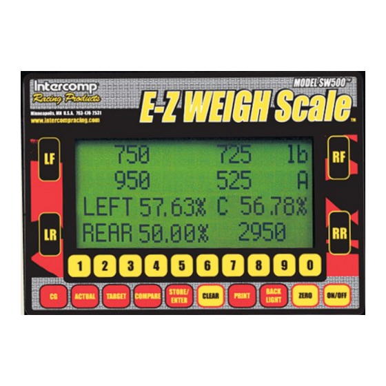
SW500 Wired Scale System 700431 Rev G, December 2021 OPERATION AUTOMOTIVE DISPLAYS The following displays are representative of the displays referenced in the Automotive Overview section. OVAL TRACK Units 725 lb A = Actual T = Target NOTE LEFT 57.63% C 56.78%... -
Page 25: Dirt Track
SW500 Wired Scale System 700431 Rev G, December 2021 OPERATION Automotive Displays (continued) DIRT TRACK LEFT 1700 57.63% REAR 1475 50.00% CROSS 1675 56.78% NOTE Rear Bite = LR - RR REAR BITE DRAG/RALLY FRONT 50.00% REAR 50.00% 2950 WHEELS AND PERCENTAGES Front % LF 750F 50.0... -
Page 26: Total
SW500 Wired Scale System 700431 Rev G, December 2021 OPERATION Automotive Displays (continued) TOTAL TOTAL: 2950 lbs TOTAL + 4 TOTAL: 2950 lbs Page 26... -
Page 27: Kart Overview
OPERATION KART OVERVIEW The SW500 Wired Scale System is designed to independently measure the force applied by each tire of a kart. The measurement is referred to as the ACTUAL weight applied by each tire. Corner weights can be entered which will be displayed as the TARGET weight. -
Page 28: Kart Displays
SW500 Wired Scale System 700431 Rev G, December 2021 OPERATION KART DISPLAYS The following displays are representative of the displays referenced in the Kart Overview section. OVAL TRACK Units 250.5 235.2 A = Actual 310. 208.0 T = Target NOTE C = Compare LEFT 55.85% C 54.33%... -
Page 29: Drag/Rally
SW500 Wired Scale System 700431 Rev G, December 2021 OPERATION Kart Displays (continued) DRAG/RALLY 250.5 235.2 lb 310.2 208.0 FRONT 48.38% REAR 51.62% 1003.9 WHEELS AND PERCENTAGES Front % LF250.5 F48.4 RF235.2 LS55.9 W54.3 RS 44.1 Left Side % Right Side % LR310.2R51.6... -
Page 30: Motorcycle Display
SW500 Wired Scale System 700431 Rev G, December 2021 OPERATION MOTORCYCLE DISPLAY When using motorcycle scale sets, use the LF (red cable) for the Front tire and the LR (white cable) for the Rear tire. When the Motorcycle display format is selected, the following screenshot will be displayed. -
Page 31: Japan Version
SW500 Wired Scale System 700431 Rev G, December 2021 OPERATION Special Displays (continued) JAPAN VERSION Simultaneously press the LF key, 2 key and CLEAR key to toggle the JAPAN display format. Turn the scale off and then turn on the scale back on. The following screenshot will be displayed. -
Page 32: Rf-Lf Cross Version
SW500 Wired Scale System 700431 Rev G, December 2021 OPERATION Special Displays (continued) RF-LF CROSS VERSION Simultaneously press the LF key, 2 key and CLEAR key to toggle the RF-LF CROSS version display format. The RF-LF Cross formula is the RF Weight minus the LF Weight. -
Page 33: Center Of Gravity
SW500 Wired Scale System 700431 Rev G, December 2021 CENTER OF GRAVITY The Center of Gravity (CG) of an object such as a car, is the point at which the object will balance when placed on a pivot point. The following diagram demonstrates two Center of Gravity scenarios where the weight is represented by the force applied by two tires of the car. -
Page 34: Standard Cg
SW500 Wired Scale System 700431 Rev G, December 2021 CENTER OF GRAVITY STANDARD CG The Standard CG calculation requires that the axle width and the wheel base dimensions be measured and entered. Prior to measuring the axle width and wheel base, verify the front tires are aligned straight forward. -
Page 35: Vertical Cg
SW500 Wired Scale System 700431 Rev G, December 2021 CENTER OF GRAVITY Standard CG (continued) 5. The Standard CG location will be displayed from the left front to right front tire and from the left front to left rear tire. Refer to the diagram on the previous page. - Page 36 SW500 Wired Scale System 700431 Rev G, December 2021 CENTER OF GRAVITY Vertical CG (continued) CALCULATING VERTICAL CG 1. Position the car level with the ground 2. Press the CG key to access the CENTER OF GRAVITY Menu. 3. Select option #2 to begin calculating Vertical CG.
-
Page 37: Serial Output
SW500 Wired Scale System 700431 Rev G, December 2021 SERIAL OUTPUT Serial Output is available on the stereo jack (RS232) and the USB port located on the left side of the indicator. The Serial Output setting has four options to choose from as shown in the following table. -
Page 38: 13-Line Continuous Output
SW500 Wired Scale System 700431 Rev G, December 2021 SERIAL OUTPUT 13-LINE CONTINUOUS OUTPUT The 13-Line Continuous Output option will transmit 13 pieces of data continuously in a repeating pattern. The following example shows a 13-Line continuous output transmission. Notes: ASCII <cr> and <lf> follow the weight. -
Page 39: Stereo Jack Rs232
SW500 Wired Scale System 700431 Rev G, December 2021 SERIAL OUTPUT STEREO JACK RS232 The RS-232 Output is accessed using the stereo jack located on the left side panel of the indicator. The Stereo Jack is typically used to connect the indicator to an optional external printer. -
Page 40: Troubleshooting
Charge batteries if using BATTERY rechargeable NiMH batteries. EEPROM ERROR EEPROM check fail. Contact Intercomp Service Department for ENTER CODE: 00 assistance. This is not an error, but a notice that the Hub Mode Compensation setting is enabled. If not using a hub plate COMPENSATION system, disable the Hub Mode. -
Page 41: Maintenance
Battery life will be less when using the backlight. The SW500 Indicator can detect when battery power is low and will flash a Low Battery message on the indicator screen. The indicator will shut off if the batteries are not charged or replaced after the low battery warning is displayed. -
Page 42: How To Contact Intercomp Service
SW500 Wired Scale System 700431 Rev G, December 2021 HOW TO CONTACT INTERCOMP SERVICE Please provide the following information when requesting service for the SW500 Wired Scale System. 1. Item Description and Part Number (if available) 2. Serial Number(s) of Item (if available) 3. - Page 43 SW500 Wired Scale System 700431 Rev G, December 2021 NOTES Page 43...
- Page 44 Corporate Office 3839 County Road 116 Medina, MN 55340 U.S.A. Tel. 763-476-2531, 1-800-328-3336 Fax: 763-476-2613 www.intercompcompany.com Intercomp Service Department 3839 County Road 116 Medina, MN 55340 U.S.A. Tel. 763-476-2531, 1-800-328-3336 Fax: 763-476-2613...
Need help?
Do you have a question about the SW500 and is the answer not in the manual?
Questions and answers