
Summary of Contents for Car System's MBUX NTG 7
- Page 1 MBUX NTG7 Video in Motion Module Installation manual MBUX NTG7 Video in Motion Module Installation manual Revision 0.1 06/2023 2023 www.carsystems.com.ua...
- Page 2 MBUX NTG7 Video in Motion Module Installation manual WARNING Qualified personnel with experience in automotive electronics, who are conversant with safety measures related to the use of electrical equipment, and who are conversant with the contents of this manual are allowed to work with the Module. BEFORE INSTALLING THE MODULE, IT IS NECESSARY: 1.
- Page 3 MBUX NTG7 Video in Motion Module Installation manual Content Warning.…………………………………………………………………..…..……………... 1. Preface.……...…………………………………………………………………………..2. Delivery kit and appearance …………………………….…………………………...….. 3. Location of the elements for Module installation.……………………………………….. 4. Block diagram ……………………………………..……………………………..... 5. Installation process..……..……………………………………..………………………. 5.1. Dismantling of interior elements to install the Module……...………………………. 5.2.
- Page 4 MBUX NTG7 Video in Motion Module Installation manual Preface This manual contains a Module installation guide and will help you to install the MBUX NTG7 Video in Motion Module (hereinafter Module). 1.1. Audience The document describes Module installation procedure and is intended for customers, partners, and employees of CarSystems.
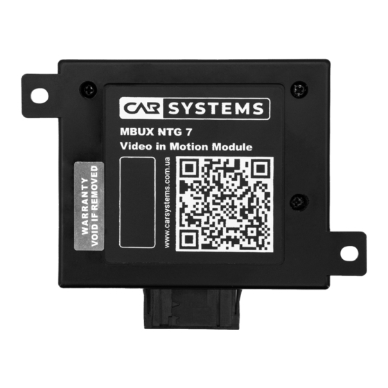
- Page 5 MBUX NTG7 Video in Motion Module Installation manual Delivery kit and appearance Picture 1 Delivery kit and appearance Delivery kit: • Module; Main connector; ETHERNET connector frame; 2 Amps FUSE. www.carsystems.com.ua Rev. 0.1 06/2023 Content...
- Page 6 MBUX NTG7 Video in Motion Module Installation manual Location of the elements for Module installation Picture 2 Elements location for Module installation Content Rev. 0.1 06/2023 www.carsystems.com.ua...
-
Page 7: Connection Diagram
MBUX NTG7 Video in Motion Module Installation manual Connection diagram Picture 3 Module connection block diagram www.carsystems.com.ua Rev. 0.1 06/2023 Content... -
Page 8: Installation Process
MBUX NTG7 Video in Motion Module Installation manual Installation process 5.1. Dismantling of interior elements to install the Module Picture 4 Detach driver's seat and tilt toward rear. Loosen the edge guard in the area of the cover and remove the cover. Remove front door sill molding. To remove door sill molding, you need to put the hand to the gray strip on the larger part and bend it towards you until a short click is heard. - Page 9 MBUX NTG7 Video in Motion Module Installation manual Picture 5 Picture 6 Unscrew the screw/bolt (Picture 6). Connect GND from the Module to vehicle. www.carsystems.com.ua Rev. 0.1 06/2023 Content...
-
Page 10: Installing The Module
MBUX NTG7 Video in Motion Module Installation manual 5.2. Installing the Module 5.2.1. Connecting the Module to the EZS ignition switch module Picture 7 Unclip EZS ignition switch module: press on the highlighted part (Picture 7) and pull down EZS ignition switch module. Content Rev. - Page 11 MBUX NTG7 Video in Motion Module Installation manual Picture 8 EZS ignition switch module connectors locations Picture 9 Remove 6 port ETHERNET connector frame from COM 3 socket. Its location is highlighted in (Picture 8) under number 3 and (Picture 9). www.carsystems.com.ua Rev.
- Page 12 MBUX NTG7 Video in Motion Module Installation manual Picture 10 6 port ETHERNET connector frame port numbering Content Rev. 0.1 06/2023 www.carsystems.com.ua...
- Page 13 MBUX NTG7 Video in Motion Module Installation manual Picture 11 www.carsystems.com.ua Rev. 0.1 06/2023 Content...
- Page 14 MBUX NTG7 Video in Motion Module Installation manual Remove Head Unit ETHERNET cable from 6 port ETHERNET connector frame: • Remove the locking bar: use tweezers to bend the plastic on the plugs as shown in (Picture 11 №1); Remove Head Unit ETHERNET cable from position slot 5 in 6 port ETHERNET connector frame: use tweezers to bend the plastic blocker as shown in (Picture 11 №2).
- Page 15 MBUX NTG7 Video in Motion Module Installation manual Picture 13 Сonnect Head Unit ETHERNET cable to ETHERNET socket from the Module: • Fix Head Unit ETHERNET cable in ETHERNET connector frame; Connect ETHERNET connector frame with Head unit ETHERNET cable to ETHERNET socket from the Module;...
- Page 16 MBUX NTG7 Video in Motion Module Installation manual 5.2.2. Connecting power wire 12 volts from Module to fuse box F152/4 Cut off the plastic tie and unscrew the screw of the power terminal Picture 14 Remove the fuse box F152/4. Tool: Simple loop is small.
- Page 17 MBUX NTG7 Video in Motion Module Installation manual Picture 15 Front side and back side fuse box F152/4 Install 2 Amps FUSE (from delivery kit) in F321 (default) and plug power wire 12 volts from the Module in A2_4 (default). *If default locations are occupied: Use 2..5 Amps FUSE and locations F328 (with A3_3 ) or F335 (with A3_10).
-
Page 18: Module Location
MBUX NTG7 Video in Motion Module Installation manual 5.3. Module location Picture 17 Content Rev. 0.1 06/2023 www.carsystems.com.ua... - Page 19 MBUX NTG7 Video in Motion Module Installation manual 6. Our contacts Email: support@carsystems.com.ua Phone: +38 (096) 809-00-11 Skype: carsystems.support Viber: +38 (096) 809-00-11 Telegram: @CarSystems_Support We provide technical support during working hours: From Monday to Friday (except public holidays). From 10:00 to 19:00 (UTC +2:00). Due to the increase in the number of unsolicited e-mails, we have strengthened our protection against spam.
Need help?
Do you have a question about the MBUX NTG 7 and is the answer not in the manual?
Questions and answers