
Subscribe to Our Youtube Channel
Related Manuals for Myenergi ZAPPI-2H22UW-T


Summary of Contents for Myenergi ZAPPI-2H22UW-T
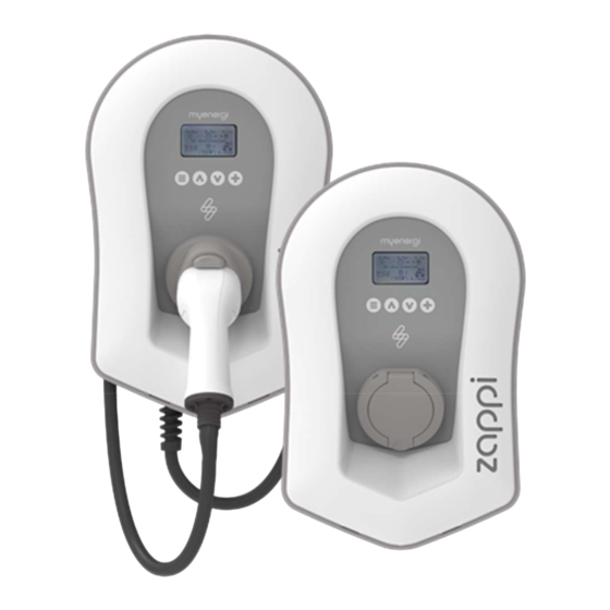
- Page 1 eco-smart EV charge point Operation & Installation Manual MODELS: ZAPPI-2H22UW - T ZAPPI-2H22TW - T ZAPPI-2H22UB - T ZAPPI-2H22TB - T Rev 2.1.8 June 2023 – ENGLISH...
- Page 2 operation and installation manual zappi...
-
Page 3: Table Of Contents
Setup ..........................................49 Troubleshooting ......................................50 Faults ..............................................51 Warranty ........................................52 Product Registration ....................................52 Technical Specifications ..................................53 myaccount ........................................56 The myenergi app ....................................... 56 The myenergi forum ....................................56 Technical Support ...................................... 56 operation and installation manual zappi... -
Page 4: Introduction
The unit is designed for indoor or outdoor use at a location with restricted access and should be mounted vertically either surface (wall) mounted or on the dedicated pole mount supplied separately by myenergi. The device has been manufactured in accordance with the state of the art and the recognised safety standards, however, incorrect operation or misuse may result in: ... -
Page 5: Box Contents
Pin-code lock function Tap operated display backlight Ethernet connector (for local communications between myenergi devices) Integral cable holster (tethered units) Supplied with 1 x clip-on grid current sensor (x3 if purchasing a 3-phase unit) ... - Page 6 Overview Overview Diagram The diagram below shows the zappi as part of a complete energy management system. Other myenergi products are shown with details of how they integrate with the grid connection and the microgeneration system. operation and installation manual...
-
Page 7: Operation
Operation Operation Controls & Indicators Display Graphical LCD display with LED backlight Backlight can be activated by tapping the unit. Front Fascia Remove fascia for installing and servicing Tethered Charging Cable if 6.5-meter cable with a Type 2 plug or Type 2 socket with locking system applicable for untethered models. -
Page 8: Display
House Load Power The power that the property is currently using in kW. (Note: This is displayed harvi only when the Generation Sensor is installed directly to a CT input or a myenergi or other device) Status Text The current status is displayed here (see Status Screens Page 12). - Page 9 Operation Display Icons Key House Consumption – Not Importing Charge Mode = FAST House Consumption – Importing Charge Mode = ECO Solar Generation Power Charge Mode = ECO+ Charge Mode = STOP Wind Generation Power zappi Device – Normal On the three phase zappi the number in the icon indicates whether the EV is charging with a single phase or all three phases.
-
Page 10: Status Screens
Operation Status Screens EV Disconnected The EV is not connected to zappi. In this example the last charging session delivered 20.8kWh of energy to the EV and 80% of that energy came from the solar panels. Waiting for Surplus zappi is waiting for sufficient surplus power from the microgeneration system. - Page 11 Operation Charging The EV is charging. In this example the car is charging in ECO+ mode at 1.6kW, there is no import or export from the grid (0.0kW) and the EV battery has charged by 8.9kWh since the car started. Charge Complete The EV is fully charged.
-
Page 12: Charging Modes
Operation Charging Modes FAST ECO+ STOP zappi has three different charging modes and a “STOP” mode which can be selected simply by pressing the buttons when the main screen is showing. The charge mode can be changed before or during a charge. Regardless of the charge mode, all the surplus electricity is used. -
Page 13: Manual Boost
The output from zappi is turned off In STOP mode zappi will not charge your EV. This includes the boost modes and timed boost. zappi will continue to measure power and communicate with the other myenergi devices. Manual Boost The Manual Boost function can only be used when charging in ECO or ECO+ mode. When boosting, the charge rate is set to maximum (just like FAST mode), until a set amount of energy has been stored in the EV's battery. - Page 14 Operation Smart Boost, and set the time you needed to leave for work, zappi automatically boosted the charge in the night to top up the battery to the required 15kWh by 7am. Activating Smart Boost When charging in ECO or ECO+ mode, press until SMART BOOST is shown.
-
Page 15: Boost Timer
Operation Boost Timer When using ECO or ECO+ charge modes, zappi can be programmed to 'boost' the current charge at certain times. When boosting, the charge rate is set to maximum (just like FAST mode), regardless of the amount of available surplus power. -
Page 16: Lock Function
Operation Boost Time Conflicts If one or more boost times conflict, the boost will follow the latest time or longest duration. Lock Function zappi can be locked from unauthorised operation. The Lock Function requires a PIN number to be entered before the unit can be operated and/or a charge is allowed. - Page 17 Operation If the ‘Lock Function’ (PIN lock) feature is enabled in the zappi, the cable will not be locked into the socket until the PIN is entered and EV charging starts. This means that if anyone plugs their cable into the zappi but they do not know the PIN they are able to remove their cable.
-
Page 18: Menus
Power from the generator (if available) Consumption: Power consumed by the house (if available) Diverted: Total diverted energy (inc. all myenergi devices) Charging: Current power being supplied to the EV Charge Energy: Energy supplied to the EV during current charge... - Page 19 Untethered zappi 3ph Tethered zappi 3ph! Information 3/5 Network ID: Network information for this device when linked to other devices using myenergi radio frequency (RF) Device Address: network (Only shows if connected to other devices) Master Address: Channel: EUI: MNID:...
- Page 20 DSR = Demand Side Response Active (Watts and time to live) See Load Balancing / Current Limiting (page 52) Information 5/5 Details of Ethernet connection (if zappi has an active Mask: Ethernet connection) plus IP addresses of myenergi Route: servers DNS: DirIP: Cloud:...
- Page 21 Menus Auto DST: Automatic Daylight-Saving Time adjustment Zone: Sets the time zone Sets the time automatically. If set to “ON” the time and Update from Cloud: date cannot be adjusted manually Display & Language Sets the Language for the main screen and menus Sound…...
-
Page 22: Advanced Menu
Note: The Network menu options only appear and can be configured on the MASTER device Linked Devices… Other myenergi devices can be wirelessly linked, this shows connected Devices… devices and their priorities. Settings for some devices are made here – see Linking Devices (page 3431) Pairing Mode…... - Page 23 Menus CT Config… CTINT: Internal CT, used to configure a group limit. See Load Balancing / Current Limiting (page 51) for details. CT1: CT2: CT3: Set the function of CT inputs – see CT Config (page 29) for more details. eSense Disabled eSense input is disabled...
-
Page 24: Configuration Settings
Configuration Configuration Settings All settings are described in the Main Menu section; however, the more commonly altered settings are described in more detail below. Time & Date The date and time are used for the Boost Timer and the savings calculations and therefore should be set correctly. In the event of a power-cut, and providing the zappi has a connection to the internet the zappi will update the time and date automatically once the power is restored. -
Page 25: Advanced Settings
Configuration Advanced Settings The Advanced Settings menu is passcode protected. The default passcode is 0 0 0 0 although it can be changed with the Passcode menu option. Supply Grid – Device Settings Phase/Phase Rotation Single Phase zappi The Phase setting is only used when installing a single phase zappi onto a 3-phase supply. -
Page 26: Supply Grid - Network Settings
Net Phases When enabled, all readings from 3-phase myenergi devices configured as 3-phase, will be netted. This means that surplus generation on ANY phase will be considered available for consumption on ANY other phase. -
Page 27: Ct Config
Configuration Export Margin This sets a minimum level of export power which is maintained when zappi is charging in ECO or ECO+ modes. Export Margin would normally be set to 0W (zero Watts) so that all available surplus will be used to charge the vehicle. - Page 28 Monitors any load, for example a washing machine or a lighting circuit. This setting can also be Monitor used to limit current drawn by myenergi devices on a particular circuit which includes other loads. See Load Balancing / Current Limiting (page 51) for more details.
-
Page 29: Preconditioning
Configuration Group Limits Current limits can be set for certain CT Groups. When a Group Limit is set the myenergi devices in the group will limit the power they draw to keep within the set limit. Group limits should be set only on the master device. See Linking Devices (page 3531) for details about master devices. - Page 30 Configuration Setting Preconditioning The preconditioning mode can set to “On” or “Off”: CT Type Function Description Once zappi detects “Charge Complete”, the next time the EV tries to draw power zappi will revert to the mode set (ie ECO, ECO+ or FAST). If zappi is in ECO+ and there is not enough surplus generation then the charge will pause and zappi will display "Waiting for surplus When preconditioning is turned ON, the amount of energy (kWh) zappi should supply to warm up the battery / precondition the EV can also be set.
-
Page 31: Esense
If the eSense input is live, zappi will not charge, regardless of set charge mode or a boost Linking Devices Up to six myenergi devices can be wirelessly linked together. By linking devices, you can use more of your own energy or have more control and visibility. Devices available now are:... - Page 32 Master & Slave Devices When two or more myenergi devices are wirelessly linked, one device will act as the master device. This device will control the other slave devices. Some settings can only be changed on the master device, e.g. Grid Limit and Net Phases.
- Page 33 Configuration All linked devices are listed in the DEVICES screen, the device shown in CAPITAL letters is the device currently being viewed. The serial number of each device is shown on the right The priority is shown on the left of each load controlling device with 1 being the highest priority. If two or more devices have equal priority, the available surplus (for that priority level) is shared between them.
-
Page 34: Wireless Connection
If you have any concerns about the wireless performance then we would be pleased to answer your questions, but please consider that if a WiFi signal works OK then there is a very high probability that the myenergi devices will also work without any issues. -
Page 35: Ethernet Connection
This Ethernet connection can be used as an alternative to connecting the myenergi devices using the wireless link. This version of the zappi can also act as the “gateway” or “hub” between all your myenergi devices and the myenergi server Note: harvi can only be connected using a wireless link to the Master device When pairing devices, they will automatically use the Ethernet link if available. -
Page 36: Installation
Installation Installation When installing and wiring the zappi, care should be taken to maintain the IP rating of the unit. Ensure that the grommets and bungs provided are fitted, the O-ring behind the cover is seated correctly and that the incoming power and CT cables are fitted using an appropriate size and type of gland. ... - Page 37 Installation Carefully drill a hole into the unit to match the size of your cable gland. Attach cable gland ensuring IP rating is met. Using zappi template mark mounting holes. For To maintain the IP rating of the unit you will need to add bungs (provided) to the unused holes.
-
Page 38: Electrical Installation
Installation Secure the unit to the wall using the fixing kit Ensure O-ring is present and sits neatly into its provided. Ensure the grommets are used to channel. maintain its IP integrity. Note: if using the rear cable entry, remember to insert the mains cable before mounting to the wall! Electrical Installation Warnings... -
Page 39: Wiring
Installation Wiring The main terminals are designed to work with wires with a diameter up to 16mm Insert the mains cable through the installed cable gland (if not already done so). Strip back outer sheath ensuring all cables reach the terminal blocks (leaving a little excess). -
Page 40: Esense Input
Installation eSense Input zappi has an “external Sense” or “eSense” input which can be used with an external input (such as a relay contact or voltage) to sense the availability of economy tariff electricity, this can be used to automatically boost the charge when in ECO or ECO+ charging modes. -
Page 41: Wiring Overview Diagram
Installation Wiring Overview Diagram operation and installation manual zappi... -
Page 42: Ct Sensor Installation
CTs can be wired to any myenergi device with CT inputs (e.g. eddi, zappi or harvi). This allows for flexible installation as a CT can be wired to the nearest device. Ideally the grid CTs should be wired to the master device. - Page 43 CTs can also be used to limit the power drawn from the supply. See Load Balancing / Current Limiting (page 5146). Additional CTs can be connected to any myenergi device with a CT input that is linked to the network (see Linking Devices on page 3331).
-
Page 44: Ct Golden Rules
Only ONE Grid CT per phase (check for only one ~ symbol in Linked Devices Info). Positioned to ‘see’ ALL import and ALL export current (i.e. always upstream of any junction box). Must be on the same phase as the master myenergi device. All CTs Arrow should point towards the consumer unit. -
Page 45: Fitting The Cover
Installation Fitting the Cover Offer cover to the enclosure, ensuring all cables are Add fascia to the enclosure cover of the zappi as neatly secured inside the unit. shown. Take particular care that the ribbon cable is not trapped between the cover and the case Ensure O-ring (seal) is firmly placed into the channel and secure the cover to the unit using the 8 screws that were removed earlier (Torque setting... -
Page 46: Advanced Installation Options
Load Balancing / Current Limiting / Load Curtailment CTs can also be used to limit the current drawn by myenergi devices to avoid overloading circuits; this is referred to as load balancing or load curtailment. There are four different ways to limit current and they can be used alone or combined for more complex situations. - Page 47 CT should be clipped around the Live cable of the supply feeding the diverter. The arrow on the CT should be pointing away from the diverter (towards the consumer unit). Wire the CT to the nearest myenergi device or use a harvi if a wireless connection is needed.
-
Page 48: Built-In Protection
If this happens and the fault cannot be reset by pressing the button for three seconds, then please contact myenergi technical support at support@myenergi.com. Over-current If there is a problem with the equipment on the EV which charges the vehicle’s battery, too much current may be drawn from the supply. -
Page 49: Setup
If zappi has been installed alongside another zappi unit or another myenergi device, refer to Linking Devices section for guidance on pairing devices. Also refer to the instruction documentation for the other devices. -
Page 50: Troubleshooting
Troubleshooting Troubleshooting Symptom Cause Solution Display is blank - There is no power to the - Check for correct supply voltage at the unit supply screw terminals (220 - 260V AC) In ECO+ mode, the charge - Grid Sensor incorrectly - Check the grid sensor is connected to a CT does not start, the display is installed... -
Page 51: Faults
Troubleshooting Faults If any of the following fault messages are displayed, follow the action described. Displayed Message Description Action Unknown Cable ! zappi has detected an unknown EV zappi will automatically retest the cable cable (untethered units only) after 5 seconds. Make sure you are using genuine IEC If the issue persists, unplug the cable 62196-2 compliant plugs. -
Page 52: Warranty
EV, or the charge has been stopped by a timer in the EV. If any of the above faults persist then stop using your zappi and contact your supplier or myenergi technical support at support@myenergi.com. Warranty Full details of the myenergi product warranty are available on our web site or by using this QR code. -
Page 53: Technical Specifications
Technical Specifications Technical Specifications Performance Mounting Location Indoor or Outdoor (permanent mounting) Charging Mode Mode 3 (IEC 61851-1 compliant communication protocol) Display Graphical backlit LCD Front LED Multicolour, according to charge status, current and user setting Charging Current 6A to 32A (variable) Dynamic Load Balancing Optional setting to limit current drawn from the unit supply or the grid Charging Profile... - Page 54 Technical Specifications Mechanical Specifications Enclosure Dimensions 439 x 282 x 122mm Protection Degree IP65 (weatherproof) ASA 6 & 3mm (UL 94 flame retardant) colours: white RAL 9016 and grey RAL Enclosure Material 9006 Operating Temperature -25°C to +40°C (Out of direct sunlight) Fixing Points In-line vertical mounting holes Weight...
- Page 55 Charging Modes Charging Modes All charging is stopped. STOP zappi will not charge the EV, Boosts (manual, smart and scheduled) are also disabled. Charge power is continuously adjusted in response to changes in generation or power consumption elsewhere in the home. Charging will continue until the vehicle is fully charged, even if power is drawn from the grid.
-
Page 56: Myaccount
Technical Support myaccount Register your myenergi devices, track your energy usage, make the most of flexible and “time of use” tariffs and much more at the myenergi online account myaccount.myenerg.com. The myenergi app We have a myenergi app for iPhone and Android devices. This allows you to control and monitor your zappi and other myenergi devices. - Page 57 Declaration of Conformity Declaration of Conformity Hereby, myenergi declares that the radio equipment type zappi eco-smart EV charge point is in compliance with Directive 2014/53/EU. The full text of the EU declaration of conformity is available at the following internet address scan the QR code below.
- Page 58 Please use the space inside the back cover of this manual to record the details of your installation and keep this information safe. Make sure you register your new zappi at myaccount.myenergi.com and also have a look at the myenergi app myenergi Designed and manufactured in the UK by myenergi Ltd, Pioneer Business Park, Faraday way,...
Need help?
Do you have a question about the ZAPPI-2H22UW-T and is the answer not in the manual?
Questions and answers