Table of Contents
Advertisement
Advertisement
Table of Contents

Related Manuals for Fujitsu FUTRO S940


Summary of Contents for Fujitsu FUTRO S940
- Page 1 Thin Client Operating Manual FUJITSU Thin Client FUTRO S940...
- Page 2 Thank you for buying an innovative product from Fujitsu. Latest information about our products, useful tips, updates etc. is available on our website: "http://www.fujitsu.com/fts/" You can find driver updates at: "http://support.ts.fujitsu.com/download" Should you have any technical questions, please contact: •...
- Page 4 Published by / Contact address in the EU Fujitsu Technology Solutions GmbH Mies-van-der-Rohe-Straße 8 80807 Munich, Germany "http://www.fujitsu.com/fts/" Copyright © Fujitsu Technology Solutions GmbH 2018. All rights reserved. Publication Date 05/2018 Order No.: A26361-K1090-Z320-1-7619, edition 1...
- Page 5 FUJITSU Thin Client FUTRO S940 Operating Manual Your FUTRO... Ports and operating elements Important notes Getting started Operation System expansions Technical data Index...
- Page 6 Information on the product description meets the design specifications of Fujitsu and is provided for comparison purposes. Several factors may cause the actual results to differ. Technical data is subject to change without prior notification. Fujitsu rejects any responsibility with regard to technical or editorial mistakes or omissions.
-
Page 7: Table Of Contents
Opening the casing ..............31 Fujitsu... - Page 8 FUJITSU Thin Client FUTRO S940 ........
-
Page 9: Your Futro
Validity of the Reference Manual This Reference Manual is valid for the following system: • FUJITSU Thin Client FUTRO S940 Notational conventions Pay particular attention to text marked with this symbol. Failure to observe these warnings could pose a risk to health, damage the device or lead to loss of data. -
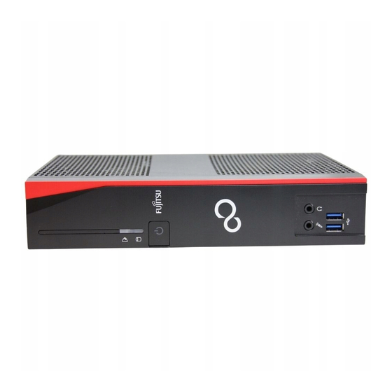
Page 10: Ports And Operating Elements
1 = SmartCard reader (optional) 5 = Microphone jack 2 = Indicator for SmartCard reader 6 = USB 3.1 Gen1 ports (USB Type-A) 3 = Flash memory or hard disk access 7 = Headphone port 4 = ON/OFF switch Fujitsu... -
Page 11: Rear View
5 = RJ45 socket (Local Area Network) with double screw security 6 = USB 2.0 ports (USB Type-A) 14 = PS/2 mouse port 7 = DisplayPort 15 = Audio input (Line In) 8 = Serial port 16 = PCI/PCIe slot Fujitsu... -
Page 12: Security Functions
If you are using the VESA sub-adapter, first connect the Kensington Lock Cable to the Security Lock device and then mount your device on the VESA sub-adapter. You can find more information in the manual for your FUJITSU FUTRO S monitor carrier. When using the Security Lock device, opening of the casing is also prevented. -
Page 13: Securing Usb Covers (Optional)
Please note that USB covers, once fitted, cannot be removed again! Ensure that you fit the USB covers the right way round. ► Insert the USB covers in the USB ports on the front of the device and push the USB covers in firmly. Fujitsu... - Page 14 ► Insert the USB covers in the USB ports on the rear side of the device and push the USB covers in firmly. In the BIOS Setup, under Advanced - USB Port Security, you can also deactivate the USB ports, in order to limit the use of USB devices. Fujitsu...
-
Page 15: Important Notes
Make sure that the rated current of the mains adapter is not higher than that of the power system to which you connect the mains adapter. ON/OFF switches do not disconnect the device from the mains voltage. To completely disconnect the mains voltage, remove the power plug from the power socket. Fujitsu... -
Page 16: Important Notes On Preparing Your Device For Use Via The Power Over Ethernet Module
IEEE 802.3at and shielded CAT 5 network cable or higher quality cable are required. Endspan devices will only be supported in conjunction with a hardware classification. Fujitsu recommends the use of the following midspan devices: • 1 port midspan from Microsemi PD-9501G: S26361-F1744-L10 •... -
Page 17: Cleaning The Device
26, on the Recovery DVD or on our website ("http://www.fujitsu.com/fts/about/fts/environment-care/"). The following sections apply to the FUJITSU Thin Client FUTRO only: Information about the "Eco-design directive": Regulation 1275/2008, based on the EU Eco-design Directive (2009/125/EU), defines requirements for the power consumption of electrical and electronic domestic and office devices in stand-by and off mode. -
Page 18: Getting Started
Proceed as follows to prepare the device for the vertical operating position: ► Disconnect the cables if required. ► Lay the device on its top (narrow side) as shown, on a stable, flat and clean surface. Fujitsu... - Page 19 To protect your device against unauthorised removal of the feet, the feet can also be secured with two screws each, of type M2.5x5 mm. These are not included in the delivery scope. ► Secure the feet with the screws (3). Fujitsu...
- Page 20 Getting started ► Stand the device on the feet. ► If necessary, reconnect any cables that were previously disconnected. Fujitsu...
-
Page 21: Horizontal Operating Position
To protect your device against unauthorised removal of the feet, the feet can also be secured with two screws each, of type M2.5x5 mm. These are not included in the delivery scope. ► Secure the feet with the screws (3). Fujitsu... - Page 22 Getting started ► Stand the device on the feet. ► If necessary, reconnect any cables that were previously disconnected. Fujitsu...
-
Page 23: Connecting External Devices
UniversalSerialBus DisplayPort PS/2 mouse port, green DisplayPort Mouseport PS/2mouseport PS/2 keyboard port, purple Keyboardport Some of the connected devices require special software (e.g. drivers) (refer to the documentation for the connected device and operating system). Fujitsu... -
Page 24: Connecting A Monitor
► Switch your device off. ► Plug the round plug of the keyboard cable into a keyboard port of the device. Keyboard, ► Switch your device on again. Fujitsu... -
Page 25: Connecting External Devices To The Serial Interface
External USB devices which you connect to one of the USB ports don’t usually need their own drivers because the software required is already included in the operating system. If the device requires separate software, please follow the instructions in the manufacturer’s documentation. Fujitsu... -
Page 26: Connecting Microphone, Headphones, Line-Out And Line-In Devices
► Connect the mains cable (1) to the mains adapter. ► Connect the mains adapter cable (2) to the DC jack (DC IN) of the device. ► Plug the mains cable (3) into a mains socket. Fujitsu... -
Page 27: Operation
Citrix and Microsoft clients as well as the optional VMware client. It has a user-friendly licence model, with the possibility of transferring licences to new devices. Updates for eLux® can be found on the Fujitsu support pages or on the Internet at "www.myelux.com". -
Page 28: Windows® 10 Iot Enterprise
The write protect filter is not enabled in the delivery state, to make it easier to adapt the thin client to your requirements. Fujitsu strongly advises that the write protect filter should be enabled during normal operation, because only then is the typical thin client high security of the device guaranteed. -
Page 29: Scout Enterprise Management Suite® - The Management Solution For Thin Clients
• Support of Wake-On-LAN and Remote Power On/Off Mirroring of desktops, encrypted and audit-proof • • Extensive diagnostic information For more information on Scout Enterprise, go to "http://www.unicon-software.com/produkte/scout-enterprise/". More information and manuals are available on the Internet at "http://www.unicon-software.com/udocs". Fujitsu... -
Page 30: Switching Off The Device
► When the system starts, press the ON/OFF switch for two to three seconds. ► Press (possibly several times) the key. BIOS Setup will be started. Select one of the tabs to access other setting options in BIOS Setup. Fujitsu... -
Page 31: Pxe System Boot
BIOS Update When should a BIOS update be performed? Fujitsu Technology Solutions makes new BIOS versions available to ensure compatibility with new operating systems, new software or new hardware. In addition, new BIOS functions can be integrated. A BIOS update should also always be performed if there is a problem that cannot be solved using new drivers or new software. -
Page 32: System Expansions
A component holder will be needed to install certain components. If the component holder is not pre-installed, follow the installation instructions in the enclosed supplement "System expansions for FUJITSU Thin Client FUTRO S940". The following illustrations may differ slightly from your device, depending on its configuration level. -
Page 33: Overview Of Optional System Components
— Parallel port — — — — — USB3.1 PCIEX4 Card — — — — — PCIe Dual Serial Card — — — — — PCIe graphics card (Low Power Version) — — USB3.1 (Type-C) with double screw security Fujitsu... -
Page 34: Information About Boards
The equipment and tools you use must be free of static charges. • Only touch or hold the boards by the edge or, if present, at the areas marked green (Touch Points). • Never touch pins or conductors on boards fitted with ESDs. Fujitsu... -
Page 35: Opening The Casing
► Remove any connected wires which are in the way. ► Loosen the screws at the rear (1). ► Slide the casing cover in the direction of the arrow (2) and swing out the casing cover towards the front (3). Fujitsu... -
Page 36: Adding Memory
(2). Removing memory modules ► Carefully push the two mounting clips outwards (1). Memory expansion Memory module The memory module snaps upwards (2). ► Pull the memory module out of its slot in the direction of the arrow (3). Fujitsu... -
Page 37: Install And Remove Smartcard Reader (Optional)
► If a PCIe board or power supply is installed, remove the cross piece and PCIe board or power supply (see "Removing the board", Page 47/"Remove power supply", Page 50). ► Carefully remove the cover of the SmartCard reader bay from the casing cover (1). Fujitsu... - Page 38 System expansions ► Place the carrier for the SmartCard reader in the casing (1). ► Fasten the carrier with the screw (2). Fujitsu...
- Page 39 ► When required, reinstall the cross piece and PCIe board or the power supply (see "Installing the board", Page 45/"Install power supply", Page 49). ► Close the casing (see "Closing the casing", Page 52). Make sure that the cables are not trapped between the casing and the components. Fujitsu...
-
Page 40: Removing The Smartcard Reader
► When required, reinstall the cross piece and PCIe board or power supply (see "Installing the board", Page 45/"Install power supply", Page 49). ► Close the casing (see "Closing the casing", Page 52). Ensure that cables are not trapped between the casing and the components. Fujitsu... -
Page 41: Install And Remove Usb Port
► Secure the USB port using the 2 x M2.5 screws provided (3), max. torque 0,4 Nm. ► Connect the cable of the USB port to the connector on the mainboard (3). ► Refit the casing cover on the casing (see chapter "Closing the casing", Page 52). Fujitsu... -
Page 42: Remove Usb Port
► Disconnect the cable of the USB port from the connector on the mainboard (1). ► Undo the screws (2) on the USB port. ► Remove the USB port (3). ► Refit the casing cover on the casing (see chapter "Closing the casing", Page 52). Fujitsu... -
Page 43: Install And Remove Loudspeaker (Optional)
► If a PCIe board or power supply is installed, remove the cross piece and PCIe board or power supply (see "Removing the board", Page 47/"Remove power supply", Page 50). ► Secure the hexagon head bolts provided into the screw holes (1). Fujitsu... - Page 44 ► When required, reinstall the cross piece and PCIe board or power supply (see "Installing the board", Page 45/"Install power supply", Page 49). ► Close the housing (see "Closing the casing", Page 52). Ensure that the cables are not trapped between the housing and the components. Fujitsu...
-
Page 45: Removing The Loudspeaker
► Lift the loudspeaker out of the casing and remove the two hexagon bolts. ► When required, reinstall the cross piece and PCIe board or power supply (see "Installing the board", Page 45/"Install power supply", Page 49). ► Close the housing (see "Closing the casing", Page 52). Fujitsu... -
Page 46: Installing And Removing A Power Over Ethernet Module (Optional)
"Removing the board", Page 47/"Remove power supply", Page 50). ► Break the cover (1) out of the casing. ► Place the Power over Ethernet module in the casing with the component side facing upwards (2). Ensure that it engages in the slot. Fujitsu... - Page 47 Make sure that the cables are not trapped between the casing and the components. Please note that no PCIe board may be installed when operating via the Power over Ethernet module (see "Important notes on preparing your device for use via the Power over Ethernet module", Page 12)! Fujitsu...
-
Page 48: Removing The Power Over Ethernet Module
► When required, reinstall the cross piece and the PCIe board (see "Installing the board", Page 45). ► Close the casing (see "Closing the casing", Page 52). Ensure that cables are not trapped between the casing and the components. Fujitsu... -
Page 49: Install And Remove Board (Optional)
► Enter the required settings for the board. ► Open the casing (see "Opening the casing", Page 31). ► Insert the riser card in its slot (1). ► Undo the screw (1) and remove the rear slot cover plate of the slot (2). Fujitsu... - Page 50 ► Install the cross piece (3). ► Secure the cross piece with the screw (4). ► Close the casing (see "Closing the casing", Page 52). Make sure that the cables do not become trapped between the casing and the components! Fujitsu...
-
Page 51: Removing The Board
► Reinstall the rear slot cover plate by inserting it in the installation slot from the inside and securing it with the screw. ► Close the casing (see "Closing the casing", Page 52). Make sure that the cables do not become trapped between the casing and the components! Fujitsu... -
Page 52: Install And Remove Power Supply (Psu, Power Supply Unit) (Optional)
Supply Unit) (optional) In addition to having power supplied via the DC input connector (DC IN) on the rear of the device, you can also operate the device via its own power supply. This will be installed in the PCI/PCIe slot. Fujitsu... -
Page 53: Install Power Supply
► Secure the power supply with the screws (2). ► Connect the cables on the mainboard (3). ► Close the casing (see "Closing the casing", Page 52). Make sure that the cables do not become trapped between the casing and the components! Fujitsu... -
Page 54: Remove Power Supply
Electromagnetic Compatibility (EMC) Directive). ► Reinstall the rear slot cover plate (see "Installing the board", Page 45). ► Close the casing (see "Closing the casing", Page 52). Make sure that the cables do not become trapped between the casing and the components! Fujitsu... -
Page 55: Replacing The Lithium Battery
► Press the catch in the direction of the arrow (1). The battery jumps out of the holder slightly. ► Remove the battery (2). ► Push the new lithium battery of the identical type into the holder (3) and press it down until it engages. Fujitsu... -
Page 56: Closing The Casing
► Replace the casing cover on the device and push it backwards. ► Secure the casing cover with the two screws on the rear of the device. Make sure that the cables are not trapped between the casing and the components. ► Connect all the cables removed before. Fujitsu... -
Page 57: Technical Data
Technical data Technical data Technicaldata FUJITSU Thin Client FUTRO S940 Electrical data Processor: Intel Pentium J5005, Gemini Lake Quad Core 1,5 GHz (max. 2,8 GHz Single Core Burst Freq.) with integrated Intel UHD Graphics 605 Rated voltage: With AC adapter: 19 – 20 V With internal PSU: 100 –... -
Page 58: Ac Adapter
• 65W: S26113-E623-V55 Model: ADP-65JH AB Internal AC adapter Electrical data Rated voltage: 100 - 240 V Max. rated current: 1,0 A 50 – 60 Hz Rated frequency: Only the following internal adapter may be used: S26113-E598-V50 Model: DPS-65AB-2A Fujitsu... -
Page 59: Index
LAN socket 7 serial interface 21 Line in 19 Device, Line out 19 opening 31 Line-out devices switching off 26 connecting 22 switching on 23 Lithium battery, transporting 12–13 replacing 51 upgrades 28 Loudspeaker Devices, installing 39 connecting 21 removing 41 Fujitsu... - Page 60 21 Property protection 8 connecting keyboard 20 Protection, property and data 8 connecting the mouse 20 PS/2 keyboard port 7 USB ports 7 PS/2 mouse port 7, 19 PS/2 mouse, connecting 20 port 20 Vertical operating position 14 Fujitsu...
Need help?
Do you have a question about the FUTRO S940 and is the answer not in the manual?
Questions and answers