Table of Contents
Advertisement
Quick Links
Operator's Manual
7-1/4 IN. SLIDING COMPOUND MITER SAW
WITH LASER TRAC
Model No. 137.322860
CAUTION:
Before using this Miter Saw,
read this manual and follow
all its Safety Rules and
Operating Instructions
For Technical Support and
Missing or Damaged Parts
1-800-843-1682
Sears Brands Management Corporation Hoffman Estates, IL 60179 USA
See the full line of Craftsman
Click on the Craftsman Club
Part No. 137322860001
®
products at craftsman.com
®
link and join today!
®
1
Safety Instructions
●
Assembly
●
Operation
●
Maintenance
●
Parts List
●
Español p. 53
●
Sears Parts &
Repair Center 1-888-
331-4569
Printed in China
Advertisement
Table of Contents

Related Manuals for Craftsman 137.322860


Summary of Contents for Craftsman 137.322860
- Page 1 Sears Parts & Missing or Damaged Parts Repair Center 1-888- 1-800-843-1682 331-4569 Sears Brands Management Corporation Hoffman Estates, IL 60179 USA See the full line of Craftsman products at craftsman.com ® Click on the Craftsman Club link and join today! ®...
-
Page 2: Table Of Contents
For 90 DAY commercial and rental terms, see the Craftsman warranty web page. This warranty gives you specific legal rights, and you may also have other rights which vary from state to state. -
Page 3: Product Specifications
PRODUCT SPECIFICATIONS MOTOR: Power Source ........120V AC, 60 Hz, 9 Amp Speed ............ 5000 RPM (No load) Electric Brake ........Yes Double Insulated ........Yes BLADE: Diameter ..........7-1/4 in. Arbor Hole ..........5/8 in. MITER SAW Rotating table: Miter Detent Stops ......... -
Page 4: Symbols
SYMBOLS WARNING ICONS Your power tool and its Operator’s Manual may contain “WARNING ICONS” (a picture symbol intended to alert you to, and/or instruct you how to avoid, a potentially hazardous condition). Understanding and heeding these symbols will help you operate your tool better and safer. Shown below are some of the symbols you may see. -
Page 5: Power Tool Safety
POWER TOOL SAFETY 7. MAKE WORKSHOP CHILD GENERAL SAFETY INSTRUCTIONS BEFORE USING THIS POWER TOOL PROOF with padlocks, master switches or by removing starter Safety is a combination of common keys. sense, staying alert and knowing how to use your power tool. 8. - Page 6 ALWAYS WEAR EYE 17. USE RECOMMENDED PROTECTION. Any power ACCESSORIES. Consult tool can throw foreign this Operator’s Manual for objects into the eyes and could recommended accessories. cause permanent eye damage. The use of improper accessories ALWAYS wear Safety Goggles (not may cause risk of injury to yourself glasses) that comply with ANSI or others.
- Page 7 22. MAINTAIN TOOLS WITH CARE. Keep tools sharp and clean for best and safest performance. Follow instructions for lubricating and changing accessories. 23. DO NOT use power tool in presence of flammable liquids or gases. 24. DO NOT operate the tool if you are under the influence of any drugs, alcohol or medicationn that could affect your ability to use the tool...
-
Page 8: Compound Miter Saw Safety
COMPOUND MITER SAW SAFETY SPECIFIC SAFETY INSTRUCTIONS 10. USE only blade collars specified for FOR THIS COMPOUND MITER SAW your saw. 1. DO NOT operate the miter saw 11. NEVER use blades larger in until it is completely assembled diameter than 7-1/4 inches. and installed according to these instructions. - Page 9 21. NEVER cut small pieces. If the immediately. Be alert at all times workpiece being cut would cause - especially during repetitive, your hand or fingers to be within monotonous operations. Don’t be 6-3/4 in. of the saw blade the lulled into carelessness due to a workpiece is too small.
-
Page 10: Electrical Requirements And Safety
ELECTRICAL REQUIREMENTS AND SAFETY POWER SUPPLY AND MOTOR To reduce the risk of electrical shock, SPECIFICATIONS this saw has a polarized plug (one The AC motor used in this saw is blade is wider than the other). This plug a universal, nonreversible type. will fit in a polarized outlet only one See “MOTOR”... - Page 11 3. If the tool suddenly stalls while Be sure your extension cord is cutting wood, release the trigger properly wired and in good condition. switch, unplug the tool, and free the Always replace a damaged extension blade from the wood. The saw may cord or have it repaired by a qualified now be started and the cut finished.
-
Page 12: Accessories And Attachments
ACCESSORIES AND ATTACHMENTS RECOMMENDED ACCESSORIES always visually examine the blade and tips for bent blade, cracks, WARNING breakage, missing or loose tips, or ● Use only accessories recommended other damage. Do not use if damage for this miter saw. Follow is suspected. -
Page 13: Tools Needed For Assembly
TOOLS NEEDED FOR ASSEMBLY Not supplied Supplied Phillips Screwdriver Blade Wrench Adjustable Wrench 8 mm, 10 mm Slotted Screwdriver Hex Wrench Combination Square COMBINATION SQUARE MUST BE TRUE Should not gap or overlap when square is flipped over (see dotted figure). Straight edge or a 3/4 in. -
Page 14: Carton Contents
CARTON CONTENTS 3. Separate all parts from the packing UNPACKING YOUR MITER SAW material. Check each one with the WARNING illustration to make certain all items are accounted for before discarding To avoid injury from unexpected any packing material. starting or electrical shock, do not plug the power cord into a source WARNING of power during unpacking and... -
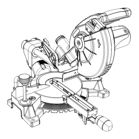
Page 15: Know Your Sliding Compound Miter Saw
KNOW YOUR SLIDING COMPOUND MITER SAW Laser horizontal Laser Trac ® adjustment knob laser guide Upper blade guard Dust bag Laser vertical adjustment knob Bevel lock knob Motor Hold-down clamp Mounting hole Base Table insert Miter handle Turntable Cutting depth stop knob Laser ON/OFF switch Hold-down latch... -
Page 16: Glossary Of Terms
GLOSSARY OF TERMS AMPERAGE (AMPS) – A measure FACE SHIELD – An impact resistant of the flow of electric current. Higher shield that helps to protect your face ratings generally means the tool is from chips, sparks, small debris. suited for heavier use. Should only be used in conjunction with additional eye protection. - Page 17 POSITIVE STOP LOCKING LEVER – KICKBACK – sudden and unintended Locks the miter saw at a preset positive movement of the tool or workpiece. It is stop for the desired miter angle. typically caused by binding or pinching of the workpiece. SWITCH HANDLE –...
-
Page 18: Assembly
ASSEMBLY Locking WARNING When transporting or storing the miter To avoid injury, do not connect this saw, the cutting head should always be miter saw to the power source until locked in the down position. it is completely assembled and 1. - Page 19 IMPORTANT: Check frequently and Fig. D-1 empty bag before it gets full. Do not use this saw to cut and/or sand metals. The hot chips or sparks may ignite sawdust from the bag material. Fig. C UNLOCKING THE SLIDE CARRIAGE (FIG.
- Page 20 NOTE: The miter saw comes with 8. Press the arbor lock (5), holding the saw blade already installed. it in firmly while turning the blade ● NEVER cut metals or masonry clockwise. The arbor lock (5) will products with this tool. This miter then engage and lock the arbor.
- Page 21 Installing the Blade (Fig. F, G, H) 6. Lower the blade guard (1) and verify the operation of the guard does not WARNING bind or stick (Fig. F). Un-plug the miter saw before 7. Be sure the arbor lock (5) is changing/installing the blade.
- Page 22 REMOVING AND INSTALLING THE MOUNTING THE MITER SAW TABLE INSERT (FIG. J) (FIG. K, L) WARNING WARNING To avoid injury from unexpected To avoid injury: saw movement: ● Always unplug the saw to avoid ● Before moving the miter saw, accidental starting.
- Page 23 Mounting instructions: Fig. L 1. For stationary use, place the saw in the desired location, directly on a 3/4 in. workbench where there is room for plywood handling and proper support of the workpiece. The base of the saw has four mounting holes.
-
Page 24: Adjustments
ADJUSTMENTS BEVEL STOP ADJUSTMENT Fig. M WARNING To avoid injury from an accidental start, make sure the switch is in the OFF position and the plug is not connected to the power source. 90° (0°) Bevel Adjustment (Fig. M) 1. Loosen bevel lock knob (1) and tilt the cutting arm completely to the right. - Page 25 45° Bevel Adjustment (Fig. M, O) has nine of the most common angle 1. Loosen the bevel lock knob (1) and setttings with positive stops at 0°, 15°, tilt the cutting head completely to 22.5°, 31.6°, and 45°. These positive the left.
- Page 26 3. Adjust the pointer (3) to the 0° mark SETTING CUTTING DEPTH (FIG. R) and retighten screw. The depth of cut can be preset for even and repetitive shallow cuts. ADJUSTING FENCE SQUARENESS 1. Adjust the cutting head down (See (FIG.
- Page 27 base or table. If the maximum depth directly through the power lead. needs readjusting: The saw must be connected to the 1. Loosen the stop knob (1) while power source and the laser on/off switch must be turned on for the moving the cutting head down until the blade extends just 1/4 in.
- Page 28 ● NOTE: All the adjustments for the normal wear and use, some occasional operation of this machine have readjustments may be necessary. been completed at the factory. WARNING Due to normal wear and use, some occasional readjustments To prevent serious injury, insert a may be necessary.
- Page 29 the “pattern line” please follow the Fig. U instructions listed below under TOP VIEW Front Line paragraph. Laser line 7. Looking at the top of the board, Cutting Blade if the laser line is not parallel to line the “pattern line” please follow the instructions listed below under Top Line paragraph.
-
Page 30: Operation
OPERATION SAFETY INSTRUCTIONS FOR BASIC adjustments, including set-up and SAW OPERATION blade changes. ● Compare the direction of rotation BEFORE USING THE MITER SAW arrow on the guard to the direction arrow on the blade. The blade teeth WARNING should always point downward at To avoid mistakes that could cause the front of the saw. - Page 31 ● Remove adjusting wrench from the ● Plan ahead to protect your eyes, tool before turning it on. hands, face and ears. ● To avoid injury from jams, slips, ● Know your miter saw. Read and or thrown pieces, use only understand this Operator’s Manual recommended accessories.
- Page 32 DRESS FOR SAFETY Never cut freehand: ● Brace your workpiece firmly against Any power tool can throw foreign objects into the eyes. the fence and table stop so it will This can result in permanent eye not rock or twist during the cut. ●...
- Page 33 ● When cutting odd shaped MAKING A BASIC CUT workpieces, plan your work so WARNING it will not bind in the blade and Body And Hand Position (Fig. Y) cause possible injury. Molding, for Never place hands near example, must lie flat or be held by the cutting area.
- Page 34 ● If the blade does not stop within NOTE: The miter saw is equipped 10 seconds, unplug the saw with an electric blade brake. When and follow the instructions in the trigger switch is released, the TROUBLESHOOTING GUIDE blade brake will stop the blade within section.
- Page 35 Fig. AA lock lever (2) and tighten the miter handle (1). The table is now locked at the desired angle. Positive stops are provided at 0°, 15°, 22.5°, 31.6° and 45°. IMPORTANT: Always tighten the miter table lock handle before performing every cutting operation.
- Page 36 Fig. CC SLIDE CUTTING WIDE BOARDS UP TO 8 IN. WIDE (FIG. EE) WARNING To avoid injury: ● Never pull the cutting head assembly and spinning blade toward you during the cut. The blade may try to climb up on the top of the workpiece, causing the cutting assembly and spinning blade to kick back forcefully.
- Page 37 8. Slowly move the switch handle (2) Fig. FF toward the fence, complete the cut. 9. Release the trigger and allow the blade to stop spinning before allowing the cutting head to raise. Fig. EE CUTTING GROOVES (FIG. GG) WARNING DO NOT USE A DADO BLADE, use only the standard saw blade for this CUTTING BOWED MATERIAL...
- Page 38 Fig. GG AUXILIARY WOOD FENCE (FIG. II) When making multiple or repetitive cuts that result in cut-off pieces of one inch or less, it is possible for the saw blade to catch the cut-off piece and throw it out of the saw or into the blade guard and housing, possibly causing damage or injury.
- Page 39 CUTTING BASE MOLDING (FIG. JJ) CUTTING CROWN MOLDING Base moldings and many other (FIG. KK, LL) moldings can be cut on a compound WARNING miter saw. The setup of the saw depends on molding characteristics Your compound miter saw is suited and application, as shown.
- Page 40 Fig. LL Settings for standard crown molding lying flat on compound miter saw table Inside corner Outside corner Compound cut crown moldings Bevel/Miter Settings NOTE: The chart below references a compound cut for crown molding ONLY WHEN THE ANGLE BETWEEN THE WALLS EQUALS 90°. BEVEL MITER TYPE OF CUT...
- Page 41 CROWN MOLDING CHART Compound Miter Saw Miter and Bevel Angle Settings Wall to Crown Molding Angle 52/38° Crown Molding 45/45° Crown Molding 52/38° Crown Molding 45/45° Crown Molding Angle Angle Miter Bevel Miter Bevel Miter Bevel Miter Bevel Between Between Setting Setting Setting...
-
Page 42: Maintenance
MAINTENANCE MAINTENANCE of the assembly go in the same hole the carbon part fits into. Tighten the DANGER cap snugly, but do not overtighten. To avoid injury, never put lubricants NOTE: To reinstall the same brushes, on the blade while it is spinning. first make sure the brushes go back in WARNING the way they came out. - Page 43 SAWDUST Fig. NN Periodically, sawdust will accumulate under the work table and base. This could cause difficulty in the movement of the worktable when setting up a miter cut. Frequently blow out or vacuum up the sawdust. WARNING Central pivot of Wear proper eye protection to keep plastic guard debris from entering eyes when...
-
Page 44: Troubleshooting Guide
TROUBLESHOOTING GUIDE WARNING To avoid injury from accidental starting, always turn switch OFF and unplug the tool before moving, replacing the blade or making adjustments. TROUBLESHOOTING GUIDE - MOTOR SUGGESTED CORRECTIVE PROBLEM PROBLEM CAUSE ACTION Brake does 1. Motor brushes not sealed or 1. - Page 45 TROUBLESHOOTING GUIDE - SAW OPERATION SUGGESTED CORRECTIVE PROBLEM PROBLEM CAUSE ACTION Blade hits table. 1. Misalignment. 1. See ADJUSTMENT- CUTTING ARM TRAVEL section. Angle of cut not 1. Miter table unlocked. 1. See OPERATION - MITER accurate. Can not 2. Sawdust under table. ANGLE ADJUSTMENT section.
-
Page 46: Parts List
MODEL NO. 137.322860 WARNING When servicing use only CRAFTSMAN replacement parts. Use of any other parts many create a HAZARD or cause product damage. Any attempt to repair or replace electrical parts on this Miter Saw may create a HAZARD unless repair is done by a qualified service technician. - Page 47 7-1/4 IN. SLIDING COMPOUND MITER SAW MODEL NO. 137.322860 PARTS LIST FOR MITER SAW (B) I.D. NO. Description Size Q’ty I.D. NO. Description Size Q’ty 3ADS HEX. NUT M6*1.0 T=5 3KXU HEX. SOC. HD. CAP BOLT M10*1.5-25 3CD5 CLAMP BOLT 3LBH CUTTER SHAFT GUARD 3DRT CLAMP BOLT 3LBJ PC-GUARD 3DWT...
- Page 48 7-1/4 IN. SLIDING COMPOUND MITER SAW MODEL NO. 137.322860 SCHEMATIC 26LU...
- Page 49 7-1/4 IN. SLIDING COMPOUND MITER SAW MODEL NO. 137.322860 PARTS LIST FOR MOTOR I.D NO. Description Size Q’ty 0HX7 NEEDLE ROLLER BEARING 0JE8 C-RING 0JX2 HEX. SOC SET SCREW M5*0.8-6 0KCQ CR. RE. PAN HD.TAPPING SCREW & WASHER M5*12-65 0KNE HEX. NUT M6*1.0 T=5 0QBE BRUSH HOLDER ASS’Y 0QBG CARBON BRUSH ASS’Y 0QBK BRUSH COVER 2BMS CUTTER SHAFT 2BMT...
-
Page 50: Repair Protection Agreements
REPAIR PROTECTION AGREEMENTS Congratulations on making a smart purchase. Your new Craftsman product ® is designed and manufactured for years of dependable operation. But like all products, it may require repair from time to time. That’s when having a Repair Protection Agreement can save you money and aggravation.