Table of Contents
Advertisement
For product information,
Owner's Manual translations,
and more, visit
www.MillerWelds.com
Big Blue 400 Pro
Kubota And Mitsubishi
Big Blue 400 PipePro
OM-278215B
Processes
Description
Engine Driven Welder/Generator
®
®
Mitsubishi
2017−02
Stick (SMAW) Welding
TIG (GTAW) Welding
MIG (GMAW) Welding
Flux Cored (FCAW) Welding
Air Carbon Arc (CAC-A)
Cutting and Gouging
®
File: Engine Drive
Advertisement
Table of Contents
Troubleshooting

Related Manuals for Miller Big Blue 400 Pro


Summary of Contents for Miller Big Blue 400 Pro
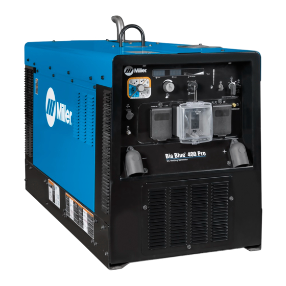
- Page 1 Stick (SMAW) Welding TIG (GTAW) Welding MIG (GMAW) Welding Flux Cored (FCAW) Welding Air Carbon Arc (CAC-A) Cutting and Gouging Description Engine Driven Welder/Generator Big Blue 400 Pro ® Kubota And Mitsubishi ® Big Blue 400 PipePro ® Mitsubishi For product information, File: Engine Drive Owner’s Manual translations,...
- Page 2 We know you don’t have time to do it any other way. That’s why when Niels Miller first started building arc welders in 1929, he made sure his products offered long-lasting value and superior quality.
-
Page 3: Table Of Contents
TABLE OF CONTENTS SECTION 1 − SAFETY PRECAUTIONS − READ BEFORE USING ....... . . 1-1. - Page 4 TABLE OF CONTENTS 6-7. Lift-Arct TIG With Auto-Stopt And Auto-Cratert ......... 6-8.
-
Page 5: Section 1 − Safety Precautions − Read Before Using
SECTION 1 − SAFETY PRECAUTIONS − READ BEFORE USING rom_2015−09 Protect yourself and others from injury — read, follow, and save these important safety precautions and operating instructions. 1-1. Symbol Usage DANGER! − Indicates a hazardous situation which, if Indicates special instructions. not avoided, will result in death or serious injury. - Page 6 D Be alert that welding sparks and hot materials from welding can FLYING METAL or DIRT can injure easily go through small cracks and openings to adjacent areas. eyes. D Watch for fire, and keep a fire extinguisher nearby. D Welding, chipping, wire brushing, and grinding D Be aware that welding on a ceiling, floor, bulkhead, or partition can cause sparks and flying metal.
-
Page 7: Engine Hazards
1-3. Engine Hazards EXHAUST SPARKS can cause fire. BATTERY EXPLOSION can injure. D Do not let engine exhaust sparks cause fire. D Always wear a face shield, rubber gloves, and D Use approved engine exhaust spark arrestor in protective clothing when working on a battery. required areas —... -
Page 8: Additional Symbols For Installation, Operation, And Maintenance
HOT METAL from air arc cutting and MOVING PARTS can injure. gouging can cause fire or explosion. D Keep away from moving parts such as fans, D Do not cut or gouge near flammables. belts and rotors. D Watch for fire; keep extinguisher nearby. D Keep all doors, panels, covers, and guards closed and securely in place. - Page 9 BATTERY CHARGING OUTPUT and BATTERY STATIC (ESD) can damage PC boards. EXPLOSION can injure. D Put on grounded wrist strap BEFORE handling Battery charging not present on all models. boards or parts. D Use proper static-proof bags and boxes to D Always wear a face shield, rubber gloves, and store, move, or ship PC boards.
-
Page 10: California Proposition 65 Warnings
1-6. California Proposition 65 Warnings For Gasoline Engines: Welding or cutting equipment produces fumes or gases which contain chemicals known to the State of California to Engine exhaust contains chemicals known to the State of cause birth defects and, in some cases, cancer. (California California to cause cancer, birth defects, or other reproduc- Health &... -
Page 11: Section 2 − Consignes De Sécurité − Lire Avant Utilisation
SECTION 2 CONSIGNES DE SÉCURITÉ − LIRE AVANT − UTILISATION fre_rom_2015−09 Pour écarter les risques de blessure pour vous−même et pour autrui — lire, appliquer et ranger en lieu sûr ces consignes relatives aux précautions de sécurité et au mode opératoire. 2-1. - Page 12 D Utiliser une protection différentielle lors de l’utilisation d’un équi- LES ACCUMULATIONS DE GAZ pement auxiliaire. Ne pas tester ni réarmer les prises femelles risquent de provoquer des blessures avec différentiel au régime de ralenti/en basse tension: cela ou même la mort. endommagerait le disjoncteur différentiel, qui ne remplirait plus son rôle de protection contre une électrocution causée par un D Fermer l’alimentation du gaz comprimé...
-
Page 13: Dangers Existant En Relation Avec Le Moteur
D Porter un équipement de protection pour le corps fait d’un matériau Si des BOUTEILLES sont endomma- résistant et ignifuge (cuir, coton robuste, laine). La protection du gées, elles pourront exploser. corps comporte des vêtements sans huile comme par ex. des gants de cuir, une chemise solide, des pantalons sans revers, des chaussures hautes et une casquette. -
Page 14: Dangers Liés À L'air Comprimé
D Pour empêcher tout démarrage accidentel pendant les travaux D Toujours vérifier le niveau de liquide de refroidissement dans le d’entretien, débrancher le câble négatif (−) de batterie de la borne. vase d’expansion (si présent), et non dans le radiateur (sauf si pré- cisé... -
Page 15: Dangers Supplémentaires En Relation Avec L'installation, Le Fonctionnement Et La Maintenance
D Pour rechercher des fuites, utiliser de l’eau savonneuse ou D Ne pas approcher les mains, cheveux, vêtements lâches et outils un détecteur à ultrasons, jamais les mains nues. En cas des organes mobiles. de détection de fuite, ne pas utiliser l’équipement. D Avant d’intervenir sur le circuit d’air comprimé, couper l’alimentation électrique, verrouiller et étiqueter l’appareil, D Remettre les portes, panneaux, recouvrements ou dispositifs... - Page 16 LA SORTIE DE RECHARGE et L’EXP- L’EMPLOI EXCESSIF peut LOSION DE LA BATTERIE peuvent SURCHAUFFER L’ÉQUIPEMENT. provoquer des blessures. D Laisser l’équipement refroidir ; respecter le fac- La recharge de batterie n’existe pas sur tous les teur de marche nominal. modèles.
-
Page 17: Proposition Californienne 65 Avertissements
D Veiller à ce que ce poste de soudage soit posé et mis à la terre il incombe à l’utilisateur de prendre des mesures supplémentaires conformément à ce mode d’emploi. telles que le déplacement du poste, l’utilisation de câbles blindés, l’utilisation de filtres de ligne ou la pose de protecteurs dans la zone D En cas d’interférences après avoir pris les mesures précédentes, de travail. - Page 18 OM-278215 Page 14...
-
Page 19: Section 3 − Definitions
Complete Parts List is available at www.MillerWelds.com SECTION 3 − DEFINITIONS 3-1. Additional Safety Symbols And Definitions Some symbols are found only on CE products. Warning! Watch Out! There are possible hazards as shown by the symbols. Safe1 2012−05 Do not discard product (where applicable) with general waste. Reuse or recycle Waste Electrical and Electronic Equipment (WEEE) by disposing at a designated collection facility. -
Page 20: Miscellaneous Symbols And Definitions
Complete Parts List is available at www.MillerWelds.com 50 h std After the first 50 hours of operation, change the engine oil and filter. Safe55 2012−05 Never use generator inside a home or garage, even if doors and win- dows are open. Safe87 2012−07 Only use generator outside and far away from windows, doors, and vents. - Page 21 Complete Parts List is available at www.MillerWelds.com Shielded Metal Arc Welding Run (Fast) Spark Arrestor (SMAW) Gas Metal Arc Engine Start Air Filter Welding (GMAW) (Engine RPM) Gas Tungsten Arc Welding (GTAW) / Engine Stop Check Air Cleaner Tungsten Inert Gas (TIG) Welding Engine Oil...
- Page 22 Complete Parts List is available at www.MillerWelds.com Notes OM-278215 Page 18...
-
Page 23: Section 4 − Specifications
Complete Parts List is available at www.MillerWelds.com SECTION 4 − SPECIFICATIONS 4-1. Serial Number And Rating Label Location The serial number and rating information for this product is located on the front. Use rating label to determine input power requirements and/or rated output. -
Page 24: Environmental Specifications
Complete Parts List is available at www.MillerWelds.com 4-4. Environmental Specifications A. IP Rating IP Rating IP23S This equipment is designed for outdoor use. It may be stored, but is not intended to be used when welding outside during precipitation unless sheltered. -
Page 25: Volt-Ampere Curves
Complete Parts List is available at www.MillerWelds.com 4-6. Volt-Ampere Curves The volt-ampere curves show the A. Stick Mode minimum and maximum voltage and amperage output capabilities of the welding generator. Curves of all other settings fall between the curves shown. 300A DC AMPERES B. -
Page 26: Ac Generator Power Curves
Complete Parts List is available at www.MillerWelds.com 4-7. AC Generator Power Curves The AC power curve shows the generator power in amperes. AC AMPERES IN 240V MODE 264 396-A 4-8. Fuel Consumption The curve shows typical fuel use under weld or power loads. 2.00 1.75 1.50... -
Page 27: Section 5 − Installation
Complete Parts List is available at www.MillerWelds.com SECTION 5 − INSTALLATION 5-1. Installing Welder/Generator Airflow Clearance 18 in. Movement (460 mm) 18 in. 18 in. (460 mm) (460 mm) 18 in. 18 in. (460 mm) (460 mm) Location/Mounting Bolting Welding Unit In Unit In Place... -
Page 28: Installing Exhaust Pipe
Complete Parts List is available at www.MillerWelds.com 5-2. Grounding Generator To Truck Or Trailer Frame GND/PE rot_grnd2 2014−11 − 800 652-D frame. Always connect a ground Equipment Grounding Terminal (On Always ground generator frame to wire from the generator equipment Front Panel) vehicle frame to prevent electric grounding terminal to bare metal on... -
Page 29: Connecting The Battery
Complete Parts List is available at www.MillerWelds.com 5-4. Connecting The Battery − Tools Needed: Shown with door 1/2 in. open and rocker panel removed. Conn_Batt2 2014−11 / S-0756-C / 161-002 NOTICE − Lead acid batteries discharge NOTICE − Wait two minutes after engine Never start the engine when the when stored in any temperature. -
Page 30: Mitsubishi Engine Oil Prestart Information
Automatic shutdown system stops engine Use fuel formulated for cold weather if oil pressure is too low or coolant tempera- NOTICE − Diesel engines in Miller equip- (diesel fuel can gel in cold weather). ture is too high. ment are meant to operate optimally at Contact local fuel supplier for fuel in- moderate to rated load. -
Page 31: Engine Fuel And Coolant Prestart Information
Complete Parts List is available at www.MillerWelds.com 5-8. Engine Fuel And Coolant Prestart Information Check radiator coolant level when fluid is low in Full recovery tank. Full Diesel Engine stops if fuel level is low. Capacity: 6 qt (5.7 L) Coolant Recovery Tank Full Cold... -
Page 32: Weld Output Terminals
Complete Parts List is available at www.MillerWelds.com 5-9. Weld Output Terminals Ref: 263 480-A For Stick and TIG welding Direct Current For Direct Current Electrode Negative Turn off power before connecting to Electrode Positive (DCEP), connect elec- (DCEN), reverse cable connections. weld output terminals. -
Page 33: Selecting Cable Sizes
**Weld cable size (AWG) is based on either a 4 volts or less drop or a current density of at least 300 circular mils per ampere. ( ) = mm for metric use ***For distances longer than those shown in this guide, call a factory applications rep. at 920-735-4505 (Miller) or 1-800-332-3281 (Hobart). Ref. S-0007-L 2015−02 5-12. Connecting To Remote Receptacle... -
Page 34: Section 6 − Operating Welder/Generator
Complete Parts List is available at www.MillerWelds.com SECTION 6 − OPERATING WELDER/GENERATOR 6-1. Front Panel Controls (See Section 6-2) 14 15 277091-A OM-278215 Page 30... -
Page 35: Description Of Front Panel Controls (See Section 6-1)
10 DC Ammeter If no remote control is connected to the Re- trol switch in Run position. mote receptacle, the front panel Voltage/Am- Ammeter displays preset amperage (Stick NOTICE − Diesel engines in Miller equipment perage control adjusts voltage and TIG only) when not welding, and actual are meant to operate optimally at moderate to amperage. -
Page 36: Process/Contactor Switch
Complete Parts List is available at www.MillerWelds.com 6-3. Process/Contactor Switch Process/Contactor Switch Weld output terminals are en- ergized when Process/Con- tactor switch is in an Elec- trode Hot position and the engine is running. Use switch to select weld process and weld output on/off control (see table below). -
Page 37: Service Menu
Complete Parts List is available at www.MillerWelds.com 6-4. Service Menu Adjust Control/Select Button Press and hold control for 5 seconds, then release to access the Service Menu. Rotate the knob to scroll through the menu items. Press and release the control to access the op- tions and information within each menu item. -
Page 38: Arc Control Settings
6-5. Arc Control Settings Arc Control is not active when the Process/Contactor switch is in the following positions: Electrode Hot − CAC-A (Air Carbon Arc Gouging) Remote ON/OFF GTAW (Remote TIG) Miller recommends Hobart filler metals. Process/Contactor Switch Arc Control SOFT Starting point for stainless steel wire (high inductance) (−25 to −1) - Page 39 Complete Parts List is available at www.MillerWelds.com Process/Contactor Switch Arc Control STOP Auto Crater on (see Section 6-4). More sensitive Auto-Crater (−5 to −1) initiation L (0) Starting point Less sensitive Auto-Crater initiation STOP (1 to 5) SOFT (−25 to −1) L (0) Starting point STIFF...
-
Page 40: Stick Start Procedure − Scratch Start Technique
Auto-Crater. Arc End With Auto-Crater While welding. Lift torch slightly to start Auto-Crater end (current is reduced). Lower torch. Weld current ramps down. Shielding gas continues until shut off. Miller recommends Hobart filler metals. WM Marketing OM-278215 Page 36... -
Page 41: Voltage/Amperage Control With 14-Pin Remote Accessory
Complete Parts List is available at www.MillerWelds.com 6-8. Voltage/Amperage Control With 14-Pin Remote Accessory Remote Receptacle Connect optional remote control to receptacle (see Section 5-12). When a remote control is con- nected to the Remote recep- tacle, the Auto Remote Sense feature automatically switches voltage/amperage control to the remote control. -
Page 42: Operating Engine Block Heater
Complete Parts List is available at www.MillerWelds.com 6-9. Operating Engine Block Heater Engine Block Heater Plug Use heater to maintain a constant engine coolant temperature. To turn on heater, connect heater plug to 120 volts AC receptacle. Mitsubishi Engine Coolant Heater Specifications Do not run engine while en- gine block heater is on. -
Page 43: Updating Software
Complete Parts List is available at www.MillerWelds.com 6-10. Updating Software Obtain the latest firmware to be loaded Confirm by rotating the Adjust Control/Se- load by rotating the Adjust Control/Select from MillerWelds.com. lect button clockwise to select YES. Then button clockwise to select YES. Then press the Select button. -
Page 44: Summary File
Complete Parts List is available at www.MillerWelds.com 6-11. Summary File Summary File Each time a USB stick is inserted in the USB receptacle, a summa- ry file is saved to the USB stick as SummaryFile.txt. The summary file provides diag- nostic and weld information. -
Page 45: Fuel/Hour Gauge Descriptions
Complete Parts List is available at www.MillerWelds.com 6-12. Fuel/Hour Gauge Descriptions OM-278215 Page 41... -
Page 46: Associating Arcreach Devices (Arcreach Models Only)
Complete Parts List is available at www.MillerWelds.com 6-13. Associating ArcReach Devices (ArcReach Models Only) Stop engine. NOTICE − Do not exceed machine duty cycle. Associating ArcReach Device To Engine Driven Welder/Generator Make connections between welder/generator and ArcReach device. See Owner’s Manual for ArcReach device for typical connection diagrams. -
Page 47: Section 7 − Operating Auxiliary Equipment
Complete Parts List is available at www.MillerWelds.com SECTION 7 − OPERATING AUXILIARY EQUIPMENT 7-1. Generator Power Receptacles 263 481-A overload. If CB5 opens, the receptacles do Use GFCI protection when operat- Test GFCI monthly. See Section 7-2 not work. Place CB5 switch in On position ing auxiliary equipment. -
Page 48: Gfci Receptacle Information, Resetting And Testing
Complete Parts List is available at www.MillerWelds.com 7-2. GFCI Receptacle Information, Resetting And Testing RotGFCI1 2016-12 If a ground fault is detected, the GFCI Reset Resetting GFCI Receptacles Use GFCI protection when operat- button pops out, and the circuit opens to ing auxiliary equipment. -
Page 49: Section 8 − Maintenance & Troubleshooting
Complete Parts List is available at www.MillerWelds.com SECTION 8 − MAINTENANCE & TROUBLESHOOTING 8-1. Mitsubishi Maintenance Label 239396-K OM-278215 Page 45... -
Page 50: Kubota Maintenance Label
Complete Parts List is available at www.MillerWelds.com 8-2. Kubota Maintenance Label 287 061-F OM-278215 Page 46... -
Page 51: Routine Maintenance
Complete Parts List is available at www.MillerWelds.com 8-3. Routine Maintenance Stop engine before maintaining. See Engine Manual and Maintenance Label Recycle engine for important start-up, service, and storage fluids. information. Service engine more often if used in severe conditions. n = Check Z = Change ~ = Clean l = Replace... -
Page 52: Servicing Air Cleaner
Complete Parts List is available at www.MillerWelds.com 8-4. Servicing Air Cleaner Stop engine. NOTICE − Do not run engine without air cleaner or with dirty element. Engine damage caused by using a damaged ele- ment is not covered by the warranty. The air cleaner primary element can be cleaned but the dirt holding capac- ity of the filter is reduced with each... -
Page 53: Checking Generator Brushes
Complete Parts List is available at www.MillerWelds.com 8-5. Checking Generator Brushes Stop engine and let cool. Generator Brush Assembly Mark and disconnect leads at brush hold- er assembly. Remove assembly. Press on brush to be sure springs compress. Replace assembly if brushes are dam- aged or if brush material is at or near mini- mum length. -
Page 54: Servicing Engine Cooling System
Complete Parts List is available at www.MillerWelds.com 8-7. Servicing Engine Cooling System Stop engine and let cool. Radiator Cap Cover Radiator Draincock Coolant Recovery Tank Change coolant according to engine manual. Add coolant according to engine maintenance label. Check coolant level in recovery tank daily. -
Page 55: Mitsubishi Engine Speed Adjustment
Complete Parts List is available at www.MillerWelds.com 8-8. Mitsubishi Engine Speed Adjustment NOTICE − Engine speed is not adjustable. Attempting engine speed adjustment may affect warranty. 8-9. Kubota Engine Speed Adjustment Engine Speed (No Load) 1890 RPM max (63 Hz) 1500 RPM (50 Hz) Stop... - Page 56 Complete Parts List is available at www.MillerWelds.com Notes OM-278215 Page 52...
-
Page 57: Overload Protection
Complete Parts List is available at www.MillerWelds.com 8-10. Overload Protection Stop engine. When a circuit breaker, supple- mentary protector, or fuse opens, it usually indicates a more serious problem exists. Contact Factory Authorized Service Agent. Fuse F1 F1 protects the stator exciter winding from overload. - Page 58 Complete Parts List is available at www.MillerWelds.com 8-11. Servicing Fuel And Lubrication Systems Stop engine and let cool. After servicing, start engine and check for fuel leaks. Stop en- gine, tighten connections as necessary, and wipe up spilled fuel. Oil Filter Oil Drain Valve And Hose Oil Fill Cap Primary Fuel Filter...
- Page 59 Complete Parts List is available at www.MillerWelds.com To replace primary fuel filter: For Kubota Engines: Turn filter counterclockwise. Remove filter. For Mitsubishi Engines: Turn filter Kubota Engine retaining ring counterclockwise to remove. Pull filter straight down to remove. Fill new filter with fresh fuel. Apply thin coat of fuel to gasket on new filter.
-
Page 60: Voltmeter/Ammeter Error Displays
Complete Parts List is available at www.MillerWelds.com 8-12. Voltmeter/Ammeter Error Displays IGBT TEMP Display Example Use the Voltmeter/Ammeter error displays to diagnose and correct fault conditions. When an error is displayed, normally weld output has stopped but generator power output may be okay. To reset error displays, stop unit and then restart. -
Page 61: Troubleshooting
Complete Parts List is available at www.MillerWelds.com 8-15. Troubleshooting Also see Voltmeter/Ammeter help displays to assist in troubleshooting weld problems (see Section 8-12). A. Welding Trouble Remedy No weld output; generator power output Place Process/Contactor switch in a Weld Terminals Always On position, or place switch in a Remote okay at AC receptacles. - Page 62 Complete Parts List is available at www.MillerWelds.com Trouble Remedy Low output at generator power AC Check engine speed, and adjust if necessary. receptacles. Check fuse F1, and replace if open (see Section 8-10). If F1 is open, have Factory Authorized Service Agent check the rotor.
-
Page 63: Section 9 − Parts List
Complete Parts List is available at www.MillerWelds.com SECTION 9 − PARTS LIST 9-1. Recommended Spare Parts Dia. Part Mkgs. Description Quantity ....276418 USB Flash Drive . -
Page 64: Section 10 − Electrical Diagrams
SECTION 10 − ELECTRICAL DIAGRAMS Figure 10-1. Circuit Diagram For Welder/Generator With Kubota Engine OM-264359 Page 60... - Page 65 276789-B OM-264359 Page 61...
- Page 66 Figure 10-2. Circuit Diagram For Welder/Generator With Mitsubishi Engine OM-264359 Page 62...
- Page 67 278214-B OM-264359 Page 63...
-
Page 68: Section 11 − Run-In Procedure
2014−09 NOTICE − Diesel engines in MILLER equipment are meant to operate optimally at moderate to rated load. Using light or no load for extended periods of time may cause wetstacking or other engine damage. Do not idle engine longer than necessary. -
Page 69: Run-In Procedure Using Load Bank Or Resistance Grid
11-2. Run-In Procedure Using Load Bank Or Resistance Grid S-0683 / S-0684 Stop engine. Weld Cables voltage and current of the generator (see nameplate, rating label, or the Resistance Grid Do not touch hot exhaust pipe, en- specifications section in this manual). gine parts, or load bank/grid. -
Page 70: Section 12 − Generator Power Guidelines
SECTION 12 − GENERATOR POWER GUIDELINES The views in this section are intended to be representative of all engine-driven welder/generators. Your unit may differ from those shown. 12-1. Selecting Equipment Generator Power Receptacles − Neutral Bonded To Frame 3-Prong Plug From Case Grounded Equipment 2-Prong Plug From Double Insulated Equipment... - Page 71 12-3. Grounding When Supplying Building Systems Equipment Grounding Terminal Grounding Cable Use #8 AWG or larger insulated copper wire. GND/PE Ground Device Use ground device as stated in electrical codes. Ground generator to system earth ground if supplying power to a premises (home, shop, farm) wiring system.
- Page 72 12-5. Approximate Power Requirements For Industrial Motors Industrial Motors Rating Starting Watts Running Watts Split Phase 1/8 HP 1/6 HP 1225 1/4 HP 1600 1/3 HP 2100 1/2 HP 3175 Capacitor Start-Induction Run 1/3 HP 2020 1/2 HP 3075 3/4 HP 4500 1400 1 HP...
- Page 73 12-7. Approximate Power Requirements For Contractor Equipment Contractor Equipment Rating Starting Watts Running Watts Hand Drill 1/4 in. 3/8 in. 1/2 in. Circular Saw 6-1/2 in. 7-1/4 in. 8-1/4 in. 1400 1400 Table Saw 9 in. 4500 1500 10 in. 6300 1800 Band Saw...
- Page 74 12-8. Power Required To Start Motor Single-Phase Induction Motor Starting Requirements Motor Start Code KVA/HP 10.0 11.2 12.5 14.0 Motor Start Code Running Amperage Motor HP Motor Voltage To find starting amperage: Step 1: Find code and use table to find kVA/HP.
- Page 75 12-10. Typical Connections To Supply Standby Power Have only qualified persons perform these connections according to all applicable codes and safety practices. Properly install, ground, and operate this equipment ac- cording Owner’s Manual and national, state, and local codes. Customer-supplied equipment is required if generator will sup- ply standby power during Fused...
- Page 76 12-11. Selecting Extension Cord (Use Shortest Cord Possible) Cord Lengths for 120 Volt Loads Use GFCI protection when operating auxiliary equipment. If unit does not have GFCI receptacles, use GFCI-protected exten- sion cord. Do not use GFCI receptacles to power life support equipment. Maximum Allowable Cord Length In ft (m) for Conductor Size In AWG (mm Current Load (Watts)
- Page 77 Notes...
- Page 78 Notes...
- Page 79 Effective January 1, 2017 (Equipment with a serial number preface of MH or newer) This limited warranty supersedes all previous Miller warranties and is exclusive with no other guarantees or warranties expressed or implied. Warranty Questions? LIMITED WARRANTY − Subject to the terms and conditions below, 6 Months —...
- Page 80 Contact the Delivering Carrier to: File a claim for loss or damage during shipment. For assistance in filing or settling claims, contact your distributor and/or equipment manufacturer’s Transportation Department. © ORIGINAL INSTRUCTIONS − PRINTED IN USA 2017 Miller Electric Mfg. Co. 2017−01...
Need help?
Do you have a question about the Big Blue 400 Pro and is the answer not in the manual?
Questions and answers