
Related Manuals for All American Scoreboards MP-4214


Summary of Contents for All American Scoreboards MP-4214
- Page 1 OPERATING INSTRUCTIONS AND SERVICE MANUAL BASKETBALL SCOREBOARD MODEL MP-4214 With MP-4000 Control EFFECTIVE S.N. 15425, MARCH 5, 1999...
-
Page 2: Table Of Contents
TABLE OF CONTENTS GENERAL INFORMATION DESCRIPTION IDENTIFICATION DAMAGE DAMAGE CLAIM PROCEDURE INSTALLATION GENERAL INFORMATION INSPECTION PRE-TEST DATA CABLE INSTALLATION ELECTRICAL CONNECTIONS CONTROL CONSOLE OPERATION SCOREBOARD POWER CONSOLE DISPLAY CONSOLE POWER TO USE SCOREBOARD TIME OF DAY OPERATION TIME SETTING AND CONTROL FINAL MINUTE 1/10 SECOND TIME OPTION TEAM SCORES HORN... - Page 3 DIAGRAMS CONTROL CONSOLE KEYBOARD AND SLIPSHEET LAYOUT SCOREBOARD SYSTEM LAYOUT SINGLE WALL JUNCTION BOX WIRING DIAGRAM (C-12675-2) DUAL WALL JUNCTION BOX WIRING DIAGRAM (C-12675-3) WIRING ORDER DIAGRAM POWER WIRING ORDER POWER SUPPLY DIAGRAM RECEIVER BOARD DIAGRAM MICROPROCESSOR 4 X 7 LED PATTERN (8 BIT) 6.10 INSTALLATION DRAWING...
-
Page 4: General Information
1. GENERAL INFORMATION 1.1 Description Your All-American scoreboard has been carefully inspected and tested before leaving the factory. It is possible, however, that components may be loosened or forced out of adjustment in transit. If this occurs, follow the troubleshooting guide (section 4). If equipment then fails to operate, contact immediately: ALL-AMERICAN Service Department EVERBRITE Corporation... -
Page 5: Installation
? ft Control Cable (if ordered) IMPORTANT! The MP-41 cable supplied by ALL AMERICAN SCOREBOARDS for use on the Microprocessor based scoreboards is specifically designed for this system. Use of a substitute cable may void the warranty on the scoreboard! 2.2 Inspection... -
Page 6: Data Cable Installation
Before installing the scoreboard, pre-test all functions. (A) Connect the scoreboard to a 15 AMP, 120 Volt AC circuit. (B) Plug the control console into the top of the scoreboard. (C) Test operate all functions on the scoreboard according to operating instructions in section 3 of this manual. -
Page 7: Console Display
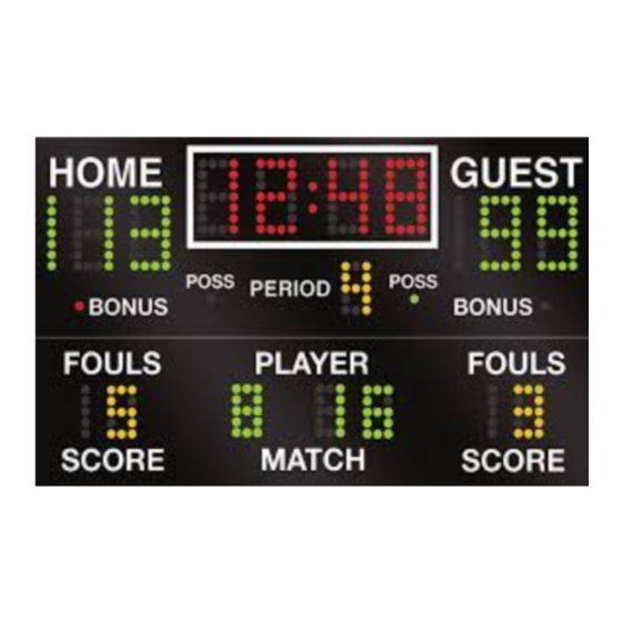
3.2 Console Display The 2 line by 20 character Liquid Crystal Display module displays the scoreboard information entered from the keyboard. The following information is displayed during normal operation: Time, Home and Guest scores, Home and Guest Team Fouls, Period, Home and Guest Bonus, Ball Possession, Auto Horn Enable, and 1/10 Second Enable. -
Page 8: Time Of Day Operation
TIME OF DAY = Push the keys for the current time, and then push ENTER . Now push DISPLAY TOD ENTER . The scoreboard will now display Time of Day. If desirable, you may disconnect the control console and put it away. If at this time you want to use the scoreboard for a ball game, input the code and it will be set for the game. -
Page 9: Team Scores
and 1/10 seconds are displayed. Push FINAL MIN 1/10 again to disable this function. 3.8 Team Scores The Home and Guest Scores can be changed in five different ways. (A) To add 1 to the existing score: Push +1 . (B) To add 2 to the existing score: Push +2 . -
Page 10: Time Outs Left
timer is not running. Push: TIME OUT TIMER to start the 1 minute timer. The LCD will show "TIME OUT = 1:00" and start to count down. When 1 minute has elapsed the internal beeper sounds, and the display returns to the current game time. If you want to return to play before the Time Out Timer gets back to zero, push: CLEAR... -
Page 11: Team Fouls
The three horizontal marks equals 3 Time Outs Left. The next time out, if you switch the time switch to time out, and push home or guest time Out, it will start the time out timer and subtract a time out from the home or guest team. -
Page 12: Wrestling Operation
CLEAR . 3.16 Wrestling Operation When using the MP-4214 scoreboard for wrestling, replace the basketball slipsheet with the wrestling slipsheet, The code is 60 for wrestling. All keyboard entries are made in the same way as for basketball, with the following exceptions: The console LCD display shows;... -
Page 13: Test Equipment
4.2 Test Equipment A simple analog or digital voltmeter will be sufficient for all user repairable problems. Printed circuit boards requiring troubleshooting should be returned to the factory. WARNING 120 VAC wires are exposed whenever the cover over the controller assembly is removed from the scoreboard. - Page 14 If the control works from the top of the scoreboard, recheck all cable connections and check continuity again. If the control still does not work, check the cable connections to the receiver board (white and green wires). If the voltage is less than 8 VAC consult the wiring instructions for long cable compensation.
- Page 15 (e) Check if LED D7 on the receiver board is on. If D7 is on, check if D5 and D6 are flashing and call customer service department. If D7 is not on, check that the receiver board is plugged into the power supply and call the customer service department.
-
Page 16: Replacement Parts List
5. REPLACEMENT PARTS LIST 5.1 Scoreboard Display Parts... - Page 17 1 DISPLAY ASSEMBLY REPLACEMENT PARTS LIST (MP-4214 Basketball) fig.& MFG PART VENDOR index NUMBER DESCRIPTION PART # 150827 Display Assembly 150826 EL00351P Receiver Board Assembly 1048-9101A BL00028P Power Supply, 100 Watt 1048-9401 BL00027P Power Supply, 200 Watt 1048-9402 EL00432P...
-
Page 18: Control Console Keyboard And Slipsheet Layout
WH009100 Ribbon Cable Assembly, 14C 8" WH009100 122763 Enclosure, 150994 Wall Junction Box, Single 150994 930895 Connector, 6 Pin Female RM12BRD6S 150500 Cable, MP-41 Control 8723 150993 Wall Junction Box, Dual 150993 930895 Connector, 6 Pin Female J1-J3 RM12BRD6S 150500 Cable, MP-41 Control 8723 6.1 Control Console Keyboard and Slipsheet Layout... - Page 19 for Wrestling Operation 6.1 Control Console Keyboard and Slipsheet Layout (cont.) for Volleyball Operation CONSOLE KEYBOARD...
-
Page 20: Scoreboard System Layout
6.2 Scoreboard System Layout... - Page 21 SYSTEM LAYOUT 6.3 Single Wall Junction Box Wiring...
- Page 22 SINGLE JUNCTION BOX WIRING 6.4 Dual Wall Junction Box Wiring...
- Page 23 DUAL JUNCTION BOX WIRING 6.5 Figuregram Data Wiring Sequence Diagram...
- Page 24 FIGURE WIRING SEQUENCE 6.6 Figuregram Power Wiring Diagram...
-
Page 25: Power Supply Diagram
FIGURE WIRING SEQUENCE 6.7 Power Supply Diagram... -
Page 26: Receiver Board Diagram
POWER SUPPLY 6.8 Receiver Board Diagram... - Page 27 DIP SWITCH SETTINGS: LED FUNCTIONS: 1 - On only when Rx is in SCBD D4 - Flashes very dimly with power up. 2 - On only when Rx is in shotclock (Indicates clock output on P1/channel 1.) 3 - Off (saved for future use) D5 - Flashes very dimly with power up.
-
Page 28: Microprocessor 4 X 7 Led Pattern (8 Bit)
6.9 Microprocessor 4 X 7 LED Pattern (8 Bit) MICROPROCESSOR 4 X 7 (8 BIT) LED PATTERN... -
Page 29: Installation Drawing
6.10 Installation Drawing INSTALLATION DRAWING...
Need help?
Do you have a question about the MP-4214 and is the answer not in the manual?
Questions and answers