Table of Contents
Advertisement
Available languages
Available languages
Quick Links
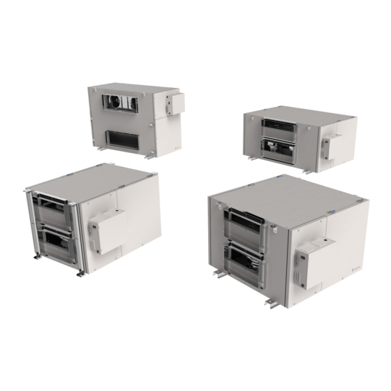
Light commercial models
Energy Recovery Ventilators
Your ventilation system should be installed in conformance with the appropriate provincial requirements or, in the absence of
such requirements, with the current edition of the National Building Code, and / or ASHRAE's "Good Engineering Practices".
United States
10048 Industrial Blvd., Lenexa, KS, 66215
Tel.: 800.747.1762 • Fax: 800.487.9915
Canada
50 Kanalflakt Way, Bouctouche, NB, E4S 3M5
Tel.: 800.565.3548 • Fax: 877.747.8116
Fantech reserves the right to modify, at any time and without notice, any or all of its products' features, designs,
components and specifications to maintain their technological leadership position.
Please visit our website www.fantech.net for more detailed technical information.
Installation Manual
SER 450 • SER 700 • SER 1100 • SER 1300
Item #: 444566
Rev Date: 2018-09-04
Advertisement
Chapters
Table of Contents

Related Manuals for Samsung SER 450


Summary of Contents for Samsung SER 450
- Page 1 Light commercial models Energy Recovery Ventilators SER 450 • SER 700 • SER 1100 • SER 1300 Your ventilation system should be installed in conformance with the appropriate provincial requirements or, in the absence of such requirements, with the current edition of the National Building Code, and / or ASHRAE’s “Good Engineering Practices”.
- Page 2 Note Warning/ Information Technical Practical tip Important information note PLEASE READ AND SAVE THESE INSTRUCTIONS Before installation, careful consideration must be given to how this system will operate if connected to any other piece of mechanical equipment, i.e. a forced air furnace or air handler, operating at a higher static. After installation, the compatibility of the two pieces of equipment must be confirmed by measuring the airflow’s of the Energy Recovery Ventilators.
-
Page 3: Table Of Contents
Table of content INSTALLATION Location ................4 Port Configuration . -
Page 4: Installation
• central vacuum system These appliances may cause lint, dust or grease to collect in the ERV , damaging the unit. Connecting any of these type of appliances to the ERV will invalidate your warranty Model SER 450 16.6 36.6 15.6 34.4... -
Page 5: Port Configuration
Port configuration The unit has access doors on the front and back. Also, the main control panel may be moved from front to back allowing for ducting layout. SER 450, SER 700 & SER 1100 WARM SIDE COLD SIDE WARM SIDE COLD SIDE Factory Setting. -
Page 6: Installing Duct Connections
Installing Drain Line Through normal operation and including defrost mode, the ERV may produce some condensation. This water should flow into a nearby drain, or be taken away by a condensate pump. The ERV and all condensate lines must be installed in a space where the temperature is maintained above the freezing point. -
Page 7: Airflow Balancing
Installing ducts to / from inside To maximize airflow in the ductwork system, all ducts should be kept short and have as few bends or elbows as possible. Forty-five degree are preferred to 90o elbows. Use “Y” tees instead of mitered tee whenever possible. All duct joints must be fastened with screws or duct sealant and wrapped with a quality duct tape to prevent leakage. -
Page 8: Installation Examples
Installation examples * Drawings are illustrations only and actual port locations and airflow directions may vary, consult unit spec sheets. It is the responsibility of the installer to ensure all ductwork is sized and installed as designed to ensure the system will perform as intended. The amount of air (CFM) that an ERV will deliver is directly related to the total external static pressure (E.S.P.) of the system. -
Page 9: Partially Dedicated Systems (Indirect Connections)
Installation examples (Cont'd) * Drawings are illustrations only and actual port locations and airflow directions may vary, consult unit spec sheets. It is the responsibility of the installer to ensure all ductwork is sized and installed as designed to ensure the system will perform as intended. The amount of air (CFM) that an ERV will deliver is directly related to the total external static pressure (E.S.P.) of the system. -
Page 10: Modes Of Operation
Modes of operation 1. Continuous / Ventilation Mode In this mode of operation both fans are operating and exchanging inside air for outside air. The energy recovery ventilator (ERV) will operate at the selected rate, either at low or medium speed, and switches to high speed when activated by an optional remote control. The "LOW (reduced)" and "HIGH (Normal)" fan speed selection will cause the unit to operate in continuous ventilation mode at a reduced exchange rate. -
Page 11: Speed Setting
Setting low speed (SER 1100 and SER 1300 ) CAUTION MAKE SURE THE POWER TO THE UNIT IS DISCONNECTED BEFORE MAKING ANY CHANGES The ERV is shipped from the factory on low speed, intermittent operation can be obtained by toggling switch located on outside of cabinet. The voltage selection for low (reduced) speed of the unit is done via jumpers shown in the illustration below. -
Page 12: Low Voltage Control System
Low Voltage Control Systems * Please see instruction manuals for individual controls for proper wiring and set up of control systems. CENTRAL CONTROLS These control options can only be used individually Ensure that unit is not CONTROLS FEATURES CONNECT TO plugged when connecting ECO-Touch®... -
Page 13: Maintenance
Maintenance CAUTION MAKE SURE UNIT IS UNPLUGGED BEFORE ATTEMPTING ANY MAINTENANCE WORK The following components should also be inspected regularly and well maintained. The motor - The motors are factory balanced and lubricated for life. They require no maintenance. The unit - The inside of the unit should be wiped clean as needed. Outside hoods - The outside hoods need to be checked every season to make sure there are no leaves or insects blocking the airflow. -
Page 14: Wiring Diagram
Wiring Diagram - SER 450 fantech... - Page 15 Wiring Diagram - SER 700 fantech...
- Page 16 Wiring Diagram - SER 1100 and SER 1300 fantech...
- Page 17 WIRING DIAGRAM (CONT'D) WIRING DIAGRAM TO Standard Furnace Interlock Wiring FURNACE THERMOSTAT TERMINALS FOUR WIRE TWO WIRE heating only RV-CTRL FOR A FURNACE CONNECTION TO 24VAC A COOLING SYSTEM: FURNACE 24-VOLT TERMINAL BLOCK COOLING SYSTEM WIRE Standard Furnace Interlock Wiring (w/Damper) THERMOSTAT TERMINALS FOUR...
- Page 18 WIRING DIAGRAM (CONT'D) WIRING DIAGRAM TO Alternate Furnace Interlock Wiring FURNACE THERMOSTAT TERMINALS FOUR WIRE TWO WIRE heating only RV-CTRL ALTERNATE FURNACE 24VAC CONNECTION: On some newer furnaces and older thermostats, energizing the R and G FURNACE terminal at the furnace has the effect 24-VOLT TERMINAL BLOCK of energizing the Y at the thermostat...
-
Page 19: Installation Verification Test
Installation Verification Test SER 450, SER 700, SER 1100, SER 1300 Models Without external control 1. Fan speed selector switch • Set fan Speed selector switch to Standby. 2. Start-up • Apply power to unit • Unit should enter Exhaust only defrost mode for a 10 second duration and the following should occur:... - Page 20 Limited Warranty • 3 Year Warranty. • Fantech ERV's have a warranty that is limited to 3 years on all parts from the date of purchase, including parts replaced during this time period. If there is no proof of purchase available, the date associated with the serial number will be used for the beginning of the warranty period. •...
- Page 21 Commerciaux Ventilateur récupérateur d'énergie SER 450 • SER 700 • SER 1100 • SER 1300 Votre système de ventilation doit être installé conformément aux exigences de la province où vous habitez ou, à défaut de telles exigences, conformément à l’édition actuelle du Code national du bâtiment du Canada ou aux « méthodes d’ingénierie appropriées »...
- Page 22 Note Avertissement/ Information Information Conseil Note importante technique pratique VEUILLEZ LIRE ET CONSERVER CES INSTRUCTIONS Avant de procéder à l’installation, examinez avec soin la façon dont le système fonctionnera s’il est relié à tout autre appareil mécanique, notamment une fournaise à air pulsé ou un appareil de traitement d’air dont la pression statique est plus élevée.
- Page 23 Table des matières INSTALLATION Emplacement ............... 24 Configuration des ports .
-
Page 24: Installation
Ces appareils peuvent produire de la poussière, des peluches ou de la graisse qui peuvent s'accumuler dans le ventilateur-récupérateur d'énergie et l'endommager. Le fait de brancher un de ces types d'appareils au VRE peut annuler la garantie. Modèles SER 450 16.6 36.6 15.6 34.4... -
Page 25: Configuration Des Ports
L'appareil possède des portes d'accès à l'avant et l'arrière. De plus, on peut déplacer le panneau de commande principal de l'avant vers l'arrière, afin de faciliter la configuration du système de gaines. SER 450 / SER 700 / SER 1100 Côté chaud Côté... -
Page 26: Installation Des Conduits
Installer la conduite de récupération des fluides Lors de son fonctionnement normal et lorsqu'il est en mode de dégivrage, le VRE peut produire de la condensation. L'eau ainsi produite doit être drainée ou retirée à l'aide d'une pompe à condensats. On doit installer le ventilateur-récupérateur de chaleur et tous les conduits de condensats dans un endroit où... -
Page 27: Équilibrage Du Débit D'air
Installation des conduits intérieurs Pour maximiser le débit d'air dans le système de gaines, on doit tenir ces dernières courtes et exemptes du plus de coudes possible. Les coudes à 45 degrés sont préférables à ceux à angle droit. Utiliser des raccords en « Y » plutôt que des T, lorsque cela est possible. On doit fixer tous les joints de gaines à... -
Page 28: Exemples D'installation
Exemples d'installation * Les dessins ne sont que des illustrations et les emplacements des entrées réelles et les directions des débits d'air peuvent varier. Consulter les fiches signalétiques des appareils. L'installateur doit s'assurer d'installer et de dimensionner tous les systèmes de gaines comme indiqué, afin que le système fonctionne comme prévu. La quantité... -
Page 29: Système Partiellement Dédidé (Connexion Indirecte)
Exemples d'installation (Suite) * Les dessins ne sont que des illustrations et les emplacements des entrées réelles et les directions des débits d'air peuvent varier. Consulter les fiches signalétiques des appareils. L'installateur doit s'assurer d'installer et de dimensionner tous les systèmes de gaines comme indiqué, afin que le système fonctionne comme prévu. -
Page 30: Modes D'opération
Modes d'opération 1. Mode continu / de ventilation Dans ce mode de fonctionnement, les deux ventilateur fonctionnent et échangent l'air avec l'extérieur. Le ventilateur récupérateur d'énergie (VRE) échange continuellement l'air à la vitesse que vous choisissez, soit à basse ou moyenne vitesse, et passe en haute vitesse lorsqu'il est activé par une télécommande en option. -
Page 31: Configurer La Vitesse
Configurer la vitesse (SER 1100 et SER 1300 ) AVERTISSEMENT ASSUREZ-VOUS QUE L'ALIMENTATION DE L'UNITÉ EST DÉCONNECTÉE AVANT DE FAIRE DES CHANGEMENTS Le VRE est expédié de l'usine à basse vitesse, un fonctionnement intermittent peut être obtenu par un commutateur de basculement situé à l'extérieur de l'armoire. -
Page 32: Systèmes De Contrôle À Basse Tension
SYSTÈME DE CONTRÔLE À BASSE TENSION * Veuillez voir les instructions individuelles des contrôles pour le câblage et la mise en pièce appropriée. CONTRÔLES CENTRALS Ces options de contrôle peuvent seulement être utilisé individuellement Assurez-vous que CONTRÔLE CARACTÉRISTIQUES CONNEXION À l'appareil n'est pas ECO-Touch®... -
Page 33: Entretien
Entretien AVERTISSEMENT S'ASSURER QUE L'APPAREIL EST DÉBRANCHÉ AVANT D'Y RÉALISER TOUT TRAVAIL D'ENTRETIEN On doit aussi inspecter les composants suivants régulièrement et les entretenir adéquatement. Moteur - Les moteurs sont équilibrés en usine et lubrifiés à vie. Ils ne nécessitent aucun entretien Appareil - On doit nettoyer l'intérieur de l'appareil à... -
Page 34: Connexions Électriques
Connexions électriques - SER 450 fantech... - Page 35 Connexions électriques - SER 700 fantech...
- Page 36 Connexions électriques - SER 1100 et SER 1300 fantech...
- Page 37 SCHÉMAS ÉLECTRONIQUES (SUITE) CONNEXION ÉLECTRIQUE Câblage standard de synchronisation avec une fournaise Standard Furnace Interlock Wiring À UNE FOURNAISE BORNES DU THERMOSTAT TERMINALS TERMINALS FOUR QUATRE FILS WIRE DEUX FILS TWO WIRE chauffage seulement heating only RV-CTRL DANS LE CAS D'UNE 24VAC FOURNAISE RACCORDÉE À...
- Page 38 SCHÉMAS ÉLECTRONIQUES (SUITE) CONNEXION ÉLECTRIQUE Contact de commande des accessoires secondaires Alternate Furnace Interlock Wiring À UNE FOURNAISE BORNES DU THERMOSTAT TERMINALS TERMINALS FOUR QUATRE FILS WIRE DEUX FILS TWO WIRE heating only chauffage seulement RV-CTRL CONNEXION ALTERNATIVE À 24VAC LA FOURNAISE Sur certaines nouvelles fournaises, et certains thermostats plus anciens,...
-
Page 39: Test De Vérification De L'installation
Test de vérification de l'installation Modèles SER 450, SER 700, SER 1100, SER 1300 Sans contrôle externe 1. Commutateur de sélection de vitesse du ventilateur • Réglez le sélecteur de vitesse du ventilateur en mode Attente (Standby) 2. Mise en service •... - Page 40 Garantie limitée • Garantie de 3 ans. • Les ventilateurs-récupérateurs d'énergie Fantech détiennent une garantie de trois (3) ans sur toutes les pièces à partir de la date d'achat, y compris les pièces remplacées pendant cette période. Si aucune preuve d'achat n'est disponible, on utilisera la date associée au numéro de série comme date d'entrée en vigueur de la garantie.
- Page 41 Parts list • Liste des composantes – SER 450 BOM # Description SER 450 (99266) Motor Assy, SHR450/700 427814 Electrostatic Filters Kit 11.5” x 15” 40328 Energy Recovery Cell 422712 x2 Kit Drain Plug 40315 x2 Drain, T 410788 Kit,RV-CTRL, Replacement,EC H:F...
- Page 42 Parts list • Liste des composantes – SER 700 BOM # Description SER 700 (99276) Motor Assy, SHR450/700 427814 Electrostatic Filters Kit 11.5” x 15” 40482 Energy Recovery Cell 422695 x2 Kit Drain Plug 40315 x2 Drain, T 410788 Kit,RV-CTRL, Replacement,EC H:F 428252 Rocker Switch 410213...
- Page 43 Parts list • Liste des composantes – SER 1100 BOM # Description SER 1100 (99277) Motor Assy, SHR450/700 427814 Electrostatic Filters Kit 11.5” x 15” 40459 Energy Recovery Cell 422695 x 3 Kit Drain Plug 40315 x2 Drain, T 410788 Kit,RV-CTRL, Replacement,EC H:F 428252 Rocker Switch...
- Page 44 Parts list • Liste des composantes – 1300 BOM # Description SER 1300 (99278) Motor Assy, R2E 250-AW-57 411728 Electrostatic Filters Kit 11.5” x 15” 40459 Heat Recovery Cell 422695 x3 Kit Drain Plug 40315 x2 Drain, T 410788 Kit,RV-CTRL, Replacement,EC H:F 428252 Rocker Switch 410213...
- Page 45 Notes fantech...
- Page 46 Notes fantech...
- Page 47 Notes fantech...
- Page 48 Fantech reserves the right to make technical changes. Fantech se réserve le droit de faire des changements For updated documentation please refer to www.fantech.net techniques. Pour de la documentation à jour, s'il vous plaît se référer au www.fantech.net Fantech® Fantech®...