
Related Manuals for MSI B650 CARBON WIFI


Summary of Contents for MSI B650 CARBON WIFI
- Page 1 MPG B650 CARBON WIFI Motherboard User Guide Benutzerhandbuch Manuel d’utilisation Руководство пользователя 取扱説明書 사용 명서 使用手冊 使用手册...
- Page 2 English...
-
Page 3: Table Of Contents
Contents Quick Start........................3 Case stand-off notification ..................5 Avoid collision notification ..................5 Specifications ......................16 Special Features ......................20 Package Contents ...................... 21 Back Panel Connectors ..................... 22 LAN Port LED Status Table .................. 23 Audio Jacks Connection ..................23 Overview of Components ................... - Page 4 Onboard LEDs ......................49 EZ Debug LED ....................... 49 LED_SW1: EZ LED Control ................... 49 JPWRLED1: LED power input ................49 Installing OS, Drivers & MSI Center ................50 MSI Center ......................53 UEFI BIOS ........................54 BIOS Setup ......................55 Resetting BIOS ......................
-
Page 5: Quick Start
Quick Start Thank you for purchasing a new motherboard from MSI®. This Quick Start section provides demonstration diagrams about how to install your computer. Some of the installations also provide video demonstrations. Please link to the URL to watch it with the web browser on your phone or tablet. - Page 6 Safety Information ∙ The components included in this package are prone to damage from electrostatic discharge (ESD). Please adhere to the following instructions to ensure successful computer assembly. ∙ Ensure that all components are securely connected. Loose connections may cause the computer to not recognize a component or fail to start.
-
Page 7: Case Stand-Off Notification
Case stand-off notification To prevent damage to the motherboard, any unnecessary mounting stand-off between the motherboard circuits and the computer case is prohibited. The Case standoff keep out zone signs will be marked on the backside of motherboard (as shown below) to serve as a warning to user. - Page 8 Installing a Processor ⚽ ∙ https://youtu.be/cltgIYiGtWY...
- Page 9 ⚠ Important If you are installing the screw-type CPU heatsink, please follow the figure below to remove the retention module first and then install the heatsink.
- Page 10 Installing DDR5 memory ⚽ ∙ https://youtu.be/XiNmkDNZcZk DIMMA1 DIMMA2 DIMMA2 DIMMA2 DIMMB2 DIMMB1 DIMMB2...
- Page 11 Connecting the Front Panel Header ⚽ ∙ http://youtu.be/DPELIdVNZUI Power LED Power Switch JFP1 Reserved HDD LED Reset Switch JFP1 HDD LED - HDD LED HDD LED + POWER LED - POWER LED POWER LED +...
- Page 12 Installing the Motherboard ⚽ ∙ https://youtu.be/wWI6Qt51Wnc Torque: 3 kgf·cm* *3 kgf·cm = 0.3 N·m BAT1 = 2.6 lbf·in...
- Page 13 Connecting the Power Connectors ⚽ ∙ http://youtu.be/gkDYyR_83I4 ATX_PWR1 CPU_PWR1~2...
- Page 14 Installing SATA Drives ⚽ ∙ http://youtu.be/RZsMpqxythc...
- Page 15 Installing a Graphics Card ⚽ ∙ http://youtu.be/mG0GZpr9w_A...
- Page 16 Connecting Peripheral Devices...
- Page 17 Power On...
-
Page 18: Specifications
Specifications ∙ Supports AMD Ryzen™ 7000 Series Desktop Processor* ∙ Supports Processor socket AM5 * Please go to www.msi.com to get the newest support status as new processors are released. Chipset AMD B650 chipset ∙ 4x DDR5 memory slots, supporting up to 128GB* ∙... - Page 19 Continued from previous column ∙ 4x M.2 slots (Key M) • M2_1 slot (From CPU) • Supports up to PCIe 5.0 x4 • Supports 2260/ 2280 storage devices • M2_2 & M2_3 slots (From CPU) M.2 SSD Slots • Supports up to PCIe 4.0 x4 •...
- Page 20 Continued from previous column ∙ 1x USB 3.2 Gen 2 10Gbps Type-C front panel connector (From B650 chipset) ∙ 1x USB 3.2 Gen 1 5Gbps connector (From B650 chipset) Internal USB Connectors • Supports additional 2 USB 3.2 Gen 1 5Gbps ports ∙...
- Page 21 ∙ UEFI AMI BIOS BIOS Features ∙ ACPI 6.4, SMBIOS 3.5 ∙ Multi-language ∙ Drivers ∙ MSI Center ∙ Realtek Console ∙ MSI App Player (BlueStacks) Software ∙ CPU-Z MSI GAMING ∙ Norton 360 Deluxe ∙ AIDA64 Extreme - MSI Edition ∙ 7-ZIP...
-
Page 22: Special Features
Special Features MSI Center Features • Front USB Type-C 10G • Gaming Mode • Server Grade PCB • Smart Priority • 2oz Copper thickened PCB • Game Highlights DIY Friendly • Mystic Light • PCI-E Steel Armor • Ambient Link •... -
Page 23: Package Contents
Package Contents Please check the contents of your motherboard package. It should contain: Board • 1x Motherboard Documentation • 1x Quick installation guide • 1x European Union regulatory notice Cables • 1x JARGB extension cable • 2x SATA 6G cables Accessories •... -
Page 24: Back Panel Connectors
Back Panel Connectors Item Description Clear CMOS button ∙ Power off your computer. Press and hold the Clear CMOS button for about 5-10 seconds to reset BIOS to default values. DisplayPort USB 3.2 Gen 2 10Gbps Type-A ports (From CPU) 2.5Gbps LAN (RJ45) port USB 2.0 Type-A ports (From B650 chipset) Wi-Fi antenna connectors... -
Page 25: Lan Port Led Status Table
LAN Port LED Status Table Speed LED Link/ Activity LED Status Speed Status Description 10 Mbps No link Green 100 Mbps/ 1 Gbps Yellow Linked Orange 2.5 Gbps Blinking Data activity Audio Jacks Connection Audio jacks to headphone and microphone diagram Audio jacks to stereo speakers diagram AUDIO INPUT... - Page 26 Audio jacks to 4-channel speakers diagram AUDIO INPUT Rear Front Audio jacks to 5.1-channel speakers diagram AUDIO INPUT Rear Front Center/ Subwoofer Audio jacks to 7.1-channel speakers diagram AUDIO INPUT Rear Front Side Center/ Subwoofer...
- Page 27 Installing antennas 1. Screw the antennas tight to the antenna connectors as shown below. 2. Orient the antennas.
-
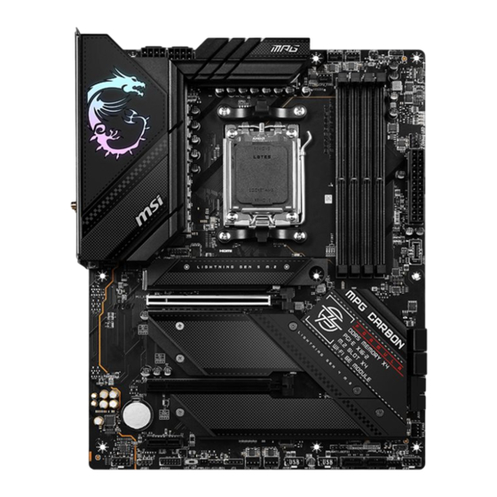
Page 28: Overview Of Components
Overview of Components JARGB_V2_2 SYS_FAN2 ATX_PWR1 JTPM1 JUSB1 M2_1 PCI_E1 M2_2 SATA ▼ _1 ▲ _2 M2_3 SATA ▼ _3 ▲ _4 PCI_E2 JUSB2 M2_4 BAT1 SYS_FAN3 JARGB_V2_1 PCI_E3 JOCFS1... -
Page 29: Cpu Socket
Always unplug the power cord from the power outlet before installing or removing ∙ the CPU. Please retain the CPU protective cap after installing the processor. MSI will deal ∙ with Return Merchandise Authorization (RMA) requests if only the motherboard comes with the protective cap on the CPU socket. -
Page 30: Dimm Slots
It is recommended to use a more efficient memory cooling system for full DIMMs ∙ installation or overclocking. The stability and compatibility of installed memory module depend on installed CPU ∙ and devices when overclocking. ∙ Please refer to www.msi.com for more information on compatible memory. -
Page 31: Pci_E1~3: Pcie Expansion Slots
PCI_E3: PCIe 3.0 x1 (From B650 Chipset) ⚠ Important If you install a large and heavy graphics card, you need to use a tool such as MSI ∙ Gaming Series Graphics Card Bolster to support its weight to prevent deformation of the slot. -
Page 32: M2_1~4: M.2 Slots (Key M)
M2_1~4: M.2 Slots (Key M) Watch the video to learn how to Install M.2 SSD with Screwless M.2 Shield Frozr heatsink. ⚽ M2_1 M2_2 M2_3 ∙ https://youtu.be/J88vcXeLido M2_4 ⚠ Important If your M.2 SSD equips its own heatsink, please remove the M.2 plates or rubber ∙... - Page 33 2. Slightly lift up the end part of Screwless M.2 Shield Frozr heatsink and move it forward to uninstall the heatsink. 3. Remove the protective films from the M.2 thermal pads on the M.2 plate. 4. If you install 2260 SSD, remove the screw from the M.2 plate and then install supplied EZ M.2 Clip kit on the M.2 plate.
- Page 34 5. Insert your M.2 SSD into the M.2 slot at a 30-degree angle. 6. Rotate the EZ M.2 Clip to fix the M.2 SSD. 30º 30º 30º 30º 2260 SSD 2280 SSD 7. Remove the protective films from the thermal pads under Screwless M.2 Shield Frozr heatsink.
- Page 35 Installing M.2 module into M2_2 & M2_3 slots 1. Loosen the screws of M.2 Shield Frozr heatsink. 2. Lift up the M.2 Shield Frozr heatsink and remove it. 3. If you want to install 2260 M.2 SSD, please install the supplied EZ M.2 Clip kit in the 2260 screw hole.
- Page 36 4. Insert your M.2 SSD into the M.2 slot at a 30-degree angle. 5. Rotate the EZ M.2 Clip to fix the M.2 SSD. 30º 30º 2260 SSD 30º 30º 2280 SSD 6. Remove the protective film from the thermal pad under the M.2 Shield Frozr heatsink.
- Page 37 Installing M.2 module into M2_4 slot 1. Loosen the screws of M.2 Shield Frozr heatsink. 2. Lift up the M.2 Shield Frozr heatsink and remove it. 3. Remove or exchange the screws according to your SSD length. Skip this step, if you install 2280 SSD.
- Page 38 4. Insert your M.2 SSD into the M.2 slot at a 30-degree angle. 5. Rotate the EZ M.2 Clip to fix the M.2 SSD. 30º 30º 30º 30º 2280/60 22110 6. Remove the protective film from the thermal pad under the M.2 Shield Frozr heatsink.
-
Page 39: Sata_1~4 & Sata_A1~2: Sata 6Gb/S Connectors
SATA_1~4 & SATA_A1~2: SATA 6Gb/s Connectors These connectors are SATA 6Gb/s interface ports. Each connector can connect to one SATA device. SATA_A2 SATA_2 SATA_1 SATA_A1 SATA_4 SATA_3 ⚠ Important ∙ Please do not fold the SATA cable at a 90-degree angle. Data loss may result during transmission otherwise. -
Page 40: Jfp1, Jfp2: Front Panel Connectors
JFP1, JFP2: Front Panel Connectors The JFP1 connector controls the power on, power reset, and the LEDs on your PC case/chassis. Power Switch/ Reset Switch headers allow you to connect power button/ reset button. Power LED header connects to LED light on the PC case, and HDD LED header indicates the activity of the hard disk. -
Page 41: Cpu_Pwr1~2, Atx_Pwr1: Power Connectors
CPU_PWR1~2, ATX_PWR1: Power Connectors These connectors allow you to connect an ATX power supply. CPU_PWR1~2 Signal Name Signal Name Ground Ground Ground Ground +12V +12V +12V +12V ATX_PWR1 Signal Name Signal Name +3.3V +3.3V Ground Ground CPU_PWR1~2 Ground PWR OK 5VSB +12V +12V... -
Page 42: Jci1: Chassis Intrusion Connector
JCI1: Chassis Intrusion Connector This connector allows you to connect the chassis intrusion switch cable. Normal Trigger the chassis (default) intrusion event Using chassis intrusion detector 1. Connect the JCI1 connector to the chassis intrusion switch/ sensor on the chassis. 2. -
Page 43: Jusb1: Usb 3.2 Gen 2 Type-C Front Panel Connector
JUSB1: USB 3.2 Gen 2 Type-C Front Panel Connector This connector allows you to connect USB 3.2 Gen 2 10Gbps Type-C connector on the front panel. The connector has a foolproof design. When you connect the cable, be sure to connect it with the corresponding orientation. USB Type-C cable JUSB1 USB Type-C port on... -
Page 44: Jusb3~4: Usb 2.0 Connectors
∙ In order to recharge your iPad, iPhone and iPod through USB ports, please install MSI Center utility. JTPM1: TPM Module Connector This connector is for TPM (Trusted Platform Module). Please refer to the TPM security platform manual for more details and usages. -
Page 45: Joc_Fs1: Safe Boot Jumper
JOC_FS1: Safe Boot Jumper This jumper is used for Safe Boot. Once enabled, the system will boot with default settings and lower PCIe (from CPU) mode. Normal Enabled (default) Apply the BIOS default settings and lower PCIe Boot with the saved (from CPU) mode for BIOS settings. -
Page 46: Cpu_Fan1, Pump_Fan1, Sys_Fan1~5: Fan Connectors
CPU_FAN1, PUMP_FAN1, SYS_FAN1~5: Fan Connectors Fan connectors can be classified as PWM (Pulse Width Modulation) Mode or DC Mode. PWM Mode fan connectors provide constant 12V output and adjust fan speed with speed control signal. DC Mode fan connectors control fan speed by changing voltage. The auto mode fan connectors can automatically detect PWM and DC mode. -
Page 47: Jbat1: Clear Cmos (Reset Bios) Jumper
JBAT1: Clear CMOS (Reset BIOS) Jumper There is CMOS memory onboard that is external powered from a battery located on the motherboard to save system configuration data. If you want to clear the system configuration, set the jumpers to clear the CMOS memory. Keep Data Clear CMOS/ (default) -
Page 48: Jrgb1: Rgb Led Connector
(12V/G/R/B) with the maximum power rating of 3A (12V). Always turn off the power supply and unplug the power cord from the power outlet ∙ before installing or removing the RGB LED strip. Please use MSI’s software to control the extended LED strip. ∙... -
Page 49: Jargb_V2_1~3: A-Rainbow V2 (Argb Gen2) Led Connectors
JARGB_V2_1~3: A-RAINBOW V2 (ARGB Gen2) LED Connectors The JARGB_V2 connectors allow you to connect the ARGB Gen2 and the ARGB-based LED strips. The JARGB_V2 connector supports up to 240 individually addressable RGB LEDs with maximum power rating of 3A (5V). Signal Name Signal Name Data... - Page 50 It is recommended that you install LED strips with the same specification to achieve the best effects. Always turn off the power supply and unplug the power cord from the power outlet ∙ before installing or removing the addressable RGB LED strip. Please use MSI’s software to control the extended LED strip. ∙...
-
Page 51: Onboard Leds
Onboard LEDs EZ Debug LED These LEDs indicate the debug status of the motherboard. CPU - indicates CPU is not detected or fail. DRAM - indicates DRAM is not detected or fail. VGA - indicates GPU is not detected or fail. BOOT - indicates the booting device is not detected or fail. -
Page 52: Installing Os, Drivers & Msi Center
Installing OS, Drivers & MSI Center Please download and update the latest utilities and drivers at www.msi.com Installing Windows 10/ Windows 11 1. Power on the computer. 2. Insert the Windows 10/ Windows 11 installation disc/USB into your computer. 3. Press the Restart button on the computer case. - Page 53 2. Select Start > Settings > Windows Update, and then select Check for updates. 3. MSI Driver Utility Installer will pop up automatically. 4. Select the I have read and agree to the MSI Terms of Use check box, and then click Next.
- Page 54 5. Check the Select All checkbox in the lower-left corner and click Install to install MSI Center and drivers. The installation progress will be shown at the bottom. 6. Once the progress has completed, click Finish.
-
Page 55: Msi Center
MSI Center is an application that helps you easily optimize game settings and smoothly use content creation softwares. It also allows you to control and synchronize LED light effects on PCs and other MSI products. With MSI Center, you can customize ideal modes, monitor system performance, and adjust fan speed. -
Page 56: Uefi Bios
UEFI has many new functions and advantages that traditional BIOS cannot achieve, and it will completely replace BIOS in the future. The MSI UEFI BIOS uses UEFI as the default boot mode to take full advantage of the new chipset capabilities. -
Page 57: Bios Setup
* When you press F10, a confirmation window appears and it provides the modification information. Select between Yes or No to confirm your choice. BIOS User Guide If you’d like to know more instructions on setting up the BIOS, please refer to https://download.msi.com/archive/mnu_exe/mb/AMDAM5BIOS.pdf or scan the QR code to access. ⚠ Important... -
Page 58: Resetting Bios
Updating BIOS Updating BIOS with M-FLASH Before updating: Please download the latest BIOS file that matches your motherboard model from MSI website. And then save the BIOS file into the USB flash drive. Updating BIOS: 1. Insert the USB flash drive that contains the update file into the USB port. - Page 59 1. Please download the latest BIOS file that matches your motherboard model from the MSI® website. 2. Rename the BIOS file to MSI.ROM, and save it to the root of the USB storage device. 3. Connect the power supply to CPU_PWR1 and ATX_PWR1. (No need to install CPU and memory.)
- Page 60 Block Diagram MPG B650 CARBON WIFI DDR5 PCIe 4x16 PCI_E1 DIMM A1/A2 PCIe 4.0 x16, x8 /x4 /x4 DIMM B1/B2 PCIe 4.0 x8 GEN5 x4 M.2_1 (PCIe Only) GEN4 x4 M.2_2,M.2_3 (PCIe Only) USB3.2 Gen2 10Gbps (Type-A) PCIe 4.0 x4 PCIe 4.0x4 PCI_E2...
- Page 61 ∙ This device may not cause harmful interference. ∙ This device must accept any interference received, including interference that may cause undesired operation. MSI Computer Corp. 901 Canada Court, City of Industry, CA 91748, USA (626)913-0828 www.msi.com...
- Page 62 ∙ ErP Directive 2009/125/EC Compliance with these directives is assessed using applicable European Harmonized Standards. The point of contact for regulatory matters is MSI-Europe: Eindhoven 5706 5692 ER Son. Products with Radio Functionality (EMF) This product incorporates a radio transmitting and receiving device. For computers in normal use, a separation distance of 20 cm ensures that radio frequency exposure levels comply with EU requirements.
- Page 63 20 cm ensures that radio frequency exposure levels comply with the Australian and New Zealand Standards. クラスB情報技術装置 この装置は 、 クラスB情報技術装置です 。 この装置は 、 家庭環境で使用することを目的とし ていますが 、 この装置がラジオやテレビジョン受信機に近接して使用されると 、 受信障害を 引き起こすことがあります 。 取扱説明書に従って正しい取り扱いをして下さい 。 VCCI-B KC인증서 상호: (주)엠에스아이코리아 제품명: 메인보드 모델명: 10-7D74 제조년월: 2022년 R-R-MSI-10-7D74 제조자 및 제조국가: MSI/중국...
- Page 64 ∙ Users should contact the local authorized point of collection for recycling and disposing of their end-of-life products. ∙ Visit the MSI website and locate a nearby distributor for further recycling information. ∙ Users may also reach us at gpcontdev@msi.com for information regarding proper Disposal, Take-back, Recycling, and Disassembly of MSI products.
- Page 65 MSI will comply with the product take back requirements at the end of life of MSI- branded products that are sold into the EU. You can return these products to local collection points.
- Page 66 MSI će poštovati zahtev o preuzimanju ovakvih proizvoda kojima je istekao vek trajanja, koji imaju MSI oznaku i koji su prodati u EU. Ove proizvode možete vratiti na lokalnim mestima za prikupljanje.
- Page 67 MSI si adeguerà a tale Direttiva ritirando tutti i prodotti marchiati MSI che sono stati venduti all’interno dell’Unione Europea alla fine del loro ciclo di vita.
- Page 68 Việt Nam RoHS Kể từ ngày 01/12/2012, tất cả các sản phẩm do công ty MSI sản xuất tuân thủ Thông tư số 30/2011/TT-BCT quy định tạm thời về giới hạn hàm lượng cho phép của một số hóa chất độc hại có trong các sản phẩm điện, điện tử”...
- Page 69 Alternatively, please try the following help resources for further guidance. ∙ Visit the MSI website for technical guide, BIOS updates, driver updates, and other information: http://www.msi.com ∙ Register your product at: http://register.msi.com Revision History ∙...
Need help?
Do you have a question about the B650 CARBON WIFI and is the answer not in the manual?
Questions and answers