Table of Contents
Advertisement
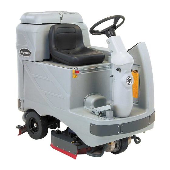
Adgressor
™
Adgressor
™
BR 850S, BR 1050S
BR 850S EDS
BR 850S EcoFlex
SERVICE MANUAL
Advance MODELS: 56390900(2820D), 56390904(3220D), 56390902(2820C), 56390906(3220C)
56390908(3520D), 56390912(3820D), 56390910(3520C), 56390914(3820C),
56390903(2820C-AXP), 56390901(2820D-AXP), 56390907(3220C-AXP), 56390905(3220D-AXP),
56390911(3520C-AXP), 56390909(3520D-AXP), 56390915(3820C-AXP), 56390913(3820D-AXP)
56381000(X2820D), 56381002(X3220D), 56381004(X3520D), 56381006(X3820D)
56381001(X2820C), 56381003(X3220C), 56381005(X3520C), 56381007(X3820C)
Nilfisk MODELS: 56390916(850S), 56390919(850SC), 56390921(1050S), 56390923(1050SC)
56390924(1050SC EDS), 56390922(1050S EDS), 56390920(850SC EDS), 56390918(850S EDS)
56381008(850S X), 56381010(1050S X), 56381009(850SC X), 56381011(1050SC X)
AXP
, Adgressor
™
, BR 1050S EDS
™
, BR 1050S EcoFlex
™
5/10 Revised 12/17 FORM NO. 56043136
EcoFlex
™
™
™
™
Advertisement
Table of Contents
Troubleshooting

Related Manuals for Nilfisk-Advance 56390900


Summary of Contents for Nilfisk-Advance 56390900
- Page 1 ™ BR 850S EcoFlex , BR 1050S EcoFlex ™ ™ SERVICE MANUAL Advance MODELS: 56390900(2820D), 56390904(3220D), 56390902(2820C), 56390906(3220C) 56390908(3520D), 56390912(3820D), 56390910(3520C), 56390914(3820C), 56390903(2820C-AXP), 56390901(2820D-AXP), 56390907(3220C-AXP), 56390905(3220D-AXP), 56390911(3520C-AXP), 56390909(3520D-AXP), 56390915(3820C-AXP), 56390913(3820D-AXP) 56381000(X2820D), 56381002(X3220D), 56381004(X3520D), 56381006(X3820D) 56381001(X2820C), 56381003(X3220C), 56381005(X3520C), 56381007(X3820C) Nilfisk MODELS: 56390916(850S), 56390919(850SC), 56390921(1050S), 56390923(1050SC)
-
Page 2: Table Of Contents
CONTENTS General Information Introduction Parts and Service Name Plate Transporting The Machine Towing Other Manuals Available Cautions And Warnings Symbols General Safety Instructions Specifications General Specifications Common to All Models Specifications Common to Deck Size Maintenance Schedule Lubricating the Machine Batteries and Chargers Wheel Drive Motor Grease Specification Know Your Machine... - Page 3 Scrub Brush System Maintenance Scrub Brush Removal and Installation (Cylindrical) Side Skirt Maintenance & Adjustment (Cylindrical) Correct Scrub Motor Wiring Connections Correct Brush Rotation Directions Solution System Functional Overview Solution Solenoid Circuit Overview Troubleshooting Guide Solution System Maintenance Solution Solenoid Removal Solenoid Valve Disassembly and Cleaning Disc Machine Solution Plumbing Detail Recovery System...
- Page 4 Main Control Board Special Program Options Low Voltage Cutout Threshold: Scrub Deck Motor Type Selection: Single or Dual Vacuum Motor Selection: Scrub Switch Operation and Scrub Pressure Limits: Restoring the Scrub Modes and Pressures to Factory Default Settings: Automatic Vacuum Shutoff Option On/Off: Vacuum Automatic Shut-off Threshold Adjustment: High Speed Scrub Option On/Off: Back-up Alarm Volume Control:...
-
Page 5: General Information
Repairs, when required, should be performed by your Authorized Nilfisk-Advance Service Center, who employs factory trained service personnel, and maintains an inventory of Nilfisk-Advance original replacement parts and accessories. Call the NILFISK-ADVANCE DEALER named below for repair parts or service. Please specify the Model and Serial Number when discussing your machine. -
Page 6: Cautions And Warnings
This machine is not suitable for picking up hazardous dust. • Do not use scarifier discs and grinding stones. Nilfisk-Advance will not be held responsible for any damage to floor surfaces caused by scarifiers or grinding stones (can also cause damage to the brush drive system). -
Page 7: Specifications
General Information SPECIFICATIONS GENERAL SPECIFICATIONS COMMON TO ALL MODELS Machine Length 61 in. (155cm) Machine Height 54in. (137.5cm) Machine Chassis Width 32 in. (82cm) Solution Tank Capacity 42 gal. (157l.) Recovery Tank Capacity 42 gal. (157l.) Sound pressure level as per IEC 60704-1 (at operator) 68 dB(A) Vibrations at the Hand Controls (ISO 5349-1) 1.12 m/s... -
Page 8: Specifications Common To Deck Size
General Information SPECIFICATIONS COMMON TO DECK SIZE Model designation: (28”)=Adgressor 2820 D and 2820 C (BR 850S / 32”)=Adgressor 3220 D and 3220 C / BR 850S, (35”)=Adgressor 3520 D and 3520 C (BR 1050S / 38”)=Adgressor 3820 D and 3820 C / BR 1050S 28”... -
Page 9: Maintenance Schedule
• Note: See the individual machine system sections for maintenance information. * Have Nilfisk-Advance: Check vacuum motor carbon brushes (Qty 2) once a year or after 300 operating hours. Check brush motor carbon brushes (Qty 4) once a year or after 500 operating hours. - Page 10 Recovery Tank Cover Gasket C D L Recovery Tank Drain Hose & Cap Flush Squeegee Pick-Up Tool & Hose Back flush Page 1 of 2 Copyright 2004 Nilfisk-Advance. 10/21/2004 10 - FORM NO. 56043136 - Adgressor / BR 850S, BR 1050S ™...
- Page 11 W worn out leaks WORK COMPLETED BY: ACKNOWLEDGED BY: Service Technician Signature Date Customer Signature Date Page 2 of 2 Copyright 2004 Nilfisk-Advance. 10/21/2004 / BR 850S, BR 1050S - 11 FORM NO. 56043136 - Adgressor ™...
-
Page 12: Know Your Machine
General Information KNOW YOUR MACHINE OVERALL MACHINE Recovery Tank Cover 10 Drive and Steer Wheel 18 Vacuum Motor Filter Housing Solution Tank Fill Cover 11 Wheel Drive Circuit Breaker 19 Squeegee Assembly Operator’s Seat 12 Control Circuit Circuit Breaker 20 Solution Filter Solution Tank Drain Hose 13 Emergency Stop Switch / Battery 21 Recovery Tank Drain Hose... -
Page 13: Control Panel
General Information CONTROL PANEL Scrub OFF Indicator Key Switch Scrub OFF Switch Battery Condition Indicator Scrub Pressure Decrease Indicator Speed Select Switch Scrub Pressure Decrease Switch Speed Select Indicator Scrub Pressure Increase Indicator Horn Switch Scrub Pressure Increase Switch Vacuum Switch Scrub Pressure / Hourmeter Display Vacuum System Indicator Wand Switch Indicator... -
Page 14: Functional Description Of Control Buttons
General Information FUNCTIONAL DESCRIPTION OF CONTROL BUTTONS: The controls on the Adgressor / BR 850S, 1050S were designed with one touch operation in mind. For single pass scrubbing the user can simply depress one switch and all systems on the machine will be ready to go. For most single-pass scrubbing operations, the operator should only need to use the top three switches on the control panel. - Page 15 General Information Scrub Pressure Increase Switch (F) – If the scrub system is off, pressing this switch will cause the following to occur: Pressure Increase / Decrease Mode (Factory Default) • The scrub system will be enabled with the scrub pressure set to the last used setting and the scrub deck will be lowered The vacuum system will be enabled and the squeegee will be lowered The solution system will be enabled The travel speed will be limited to the scrub speed setting...
-
Page 16: Description Of Indicators On The Control Panel
General Information DESCRIPTION OF INDICATORS ON THE CONTROL PANEL: In general, the following guidelines apply to the control panel indicators: A steady red indicator means that the function is inhibited for some reason. For example, if the scrub system is off and the operator is not on the seat, the scrub system indicator will be red indicating that the system cannot be turned on until the operator is on the seat. -
Page 17: Description Of The Battery Condition Indicators
General Information DESCRIPTION OF THE BATTERY CONDITION INDICATORS The battery condition indicator (J) consists of three lights, a green (G), a yellow (Y), and a red (R). The voltage indication will change based on the cutoff level (standard or alternate) selected in the control unit. The battery voltage ranges for the various indications are listed below: Standard Alternate Green... -
Page 18: Steering System
Steering System STEERING SYSTEM STEERING COLUMN ASSEMBLY SHROUD REMOVAL Upper Column See Figure 1. Remove the center Wheel Adapter (A) from the steering wheel. Pry it off using a flat bladed screwdriver. Remove the steering shaft retainer Hex Nut (B) (use a 3/4” socket wrench) and the two Washers (C & D). Next pull straight back on the steering wheel to remove it from the metal Wheel Adapter (E). -
Page 19: Steering Chain Removal And Tensioning
Steering System STEERING CHAIN REMOVAL AND TENSIONING Turn the master key switch off and separate the battery pack emergency disconnect (13). See Figure 2. From underneath the front of the machine loosen the (4) (M) Screws and push the lower steering column to the rear of the machine. -
Page 20: Wheel Drive System
Wheel Drive System WHEEL DRIVE SYSTEM GENERAL FUNCTIONAL OVERVIEW See Figures 1 & 2. An 1100-watt 1.5 HP (permanent magnet) 36V motor/gear transmission combination wheel (M3) unit is used to propel all machines. A Curtis model 1237 PMC solid state speed controller (A1) regulates (outputs) the variable speed Fwd/Rev wheel drive motor functions. - Page 21 Wheel Drive System FIGURE 1 FIGURE 2 BRN/BLK CIRCUIT BREAKER, 70 AMP CONTACT N.O. BRN/YEL CIRCUIT BREAKER, 10 AMP SW, SEAT FUSE, 1 A. SPST KEY MAIN CONTACTOR ORN/BLU RED/BLK BLU/BLK RED/GRN THERMISTOR J4-1 HORN + INTERFACE WHT/YEL YEL/BLK J4-7 J2-9 S P E E D L I M I T HORN -...
- Page 22 Wheel Drive System FIGURE 3 A1 Speed Control Pin Connection 5.75K Ohms 250 Ohms Main Control Resistance Board (Partial) WHT/YEL J2-9 Speed Limit WIPER J4-9 Pot. LO J4-3 Pot. HI Approximate R1 Voltage Values 0.87 – 2.19V Reverse 2.19 – 4.1V Forward This drawing shows additional controller input circuit detail.
-
Page 23: Low Current A1 Speed Control Pin Key Detail
Wheel Drive System LOW CURRENT A1 SPEED CONTROL PIN KEY DETAIL Pin # Wire Color Controller Pin Description & Function Throttle Pot R1 pot high input Throttle Pot R1 pot wiper input Throttle Pot R1 pot low input Wht/Yel Speed limit pot input Tied to Pot High –... -
Page 24: Steering Spindle And Wheel Drive Motor Assembly Removal
Wheel Drive System STEERING SPINDLE AND WHEEL DRIVE MOTOR ASSEMBLY REMOVAL WARNING! Turn the main key switch (J) to the off position and disconnect the battery pack by pushing in the emergency disconnect lever (13). Next block both rear wheels so machine can’t roll. See Figure 5. - Page 25 Wheel Drive System FIGURE 5 FRONT / BR 850S, BR 1050S - 25 FORM NO. 56043136 - Adgressor ™...
-
Page 26: Brake Adjustment
Wheel Drive System BRAKE ADJUSTMENT See Figure 6. Adjust the (E) brake rod’s length to eliminate any foot pedal free play (space between the pedal and rod end) when the pedal is at rest (not being engaged). The rod length can be changed by loosening the jam nut (S) and threading the adjustment screw (T) In or Out. To access the brake rod remove the front pedal mounting hardware items (B &... -
Page 27: Drive Wheel Brake Strap Replacement
Wheel Drive System DRIVE WHEEL BRAKE STRAP REPLACEMENT WARNING! Turn the key switch to the off position and then disconnect the battery pack by activating the emergency stop switch/battery disconnect lever (13). See Figure 7. Remove from the brake band (U) the front lower outside retainer ring (V) (external type). Service Tip: Use retaining pliers (tip size .038 inches/1 mm) to prevent damage when removing all retainer rings. -
Page 28: Potentiometer Testing
Wheel Drive System POTENTIOMETER TESTING The Potentiometer is part of the drive pedal assembly. It is not serviced separately and does not require adjustment Testing the Potentiometer Note: The pot doesn’t have to be removed from the drive pedal assembly to test. Jack the front drive wheel off the floor and support the machine with jack stands and wheel chocks. -
Page 29: Potentiometer Adjustment
Wheel Drive System POTENTIOMETER ADJUSTMENT WARNING! The potentiometer should not normally need adjustment because it is pre-set by the factory when it is mounted on the drive pedal However, if the potentiometer is loosened or removed it can be readjusted using an ohmmeter. The wiper should be perfectly “centered” when in the neutral position. -
Page 30: Scrub Brush System
Scrub Brush System SCRUB BRUSH SYSTEM FUNCTIONAL OVERVIEW • Disc Brush System Overview See Figure 2. The Adgressor 2820D, 3220D, 3520D, 3820D / BR 850S, 1050S use the disc type scrub system. A single 1, 1-1/2HP 36V DC permanent magnet motor is connected at both ends with (2) 90-degree gearboxes that drive the two disc (rotary) brushes. The 3520D – 3820D models use the disc type scrub system also but with (3) .6HP 36V horizontally mounted DC permanent magnet motor gearbox assemblies. -
Page 31: Scrub Brush System Troubleshooting
Scrub Brush System SCRUB BRUSH SYSTEM TROUBLESHOOTING On all models (disc & cylindrical) the scrub system’s major electrical components are monitored by the main controller (E1) to detect any system function failures (error codes). The system components covered are the brush motor(s) (M7 & M8), brush solenoid (K1) and brush lift actuator motor (M1). -
Page 32: Scrub Brush Deck Removal (Disc & Cylindrical)
Scrub Brush System SCRUB BRUSH DECK REMOVAL (DISC & CYLINDRICAL) Remove both deck side skirt assemblies. NOTE: This step is optional, you may find deck removal easier with the skirts removed. Lower the scrub deck with brushes (pads) installed. ATTENTION: Don’t turn the key switch off until after disconnecting the battery pack by pushing in (activating) the Emergency Disconnect (13). -
Page 33: Scrub Brush Motor Assembly Removal (Disc)
Service Tip: Apply a small amount of grease or “Never Seize” to the gearbox output shafts when reinstalling the drive Hub(s) (I). Note: The gearbox output shafts rotate the brush holders in the opposite direction of other Nilfisk-Advance automatic scrubbers (see below). FRONT... -
Page 34: Scrub Brush Side Skirt Replacement (Disc)
Scrub Brush System SCRUB BRUSH SIDE SKIRT REPLACEMENT (DISC) See Figure 4. Loosen the (4) side skirt Retainer Knobs (V) (2 per side) and pull the Skirt Assemblies (W) off from the scrub deck. Remove all the hardware that holds the blade and retainer to the skirt housing. Each of the (2) blades has 2 working edges. -
Page 35: Brush Deck Actuator Removal (Disc & Cylindrical)
Scrub Brush System BRUSH DECK ACTUATOR REMOVAL (DISC & CYLINDRICAL) Lower the scrub deck with the scrub brushes installed. Don’t turn the key switch off until disconnecting the battery pack by using the emergency disconnect lever (13). This procedure is done to prevent the scrub deck from automatically raising when the key is turned off. See Figure 5. -
Page 36: Scrub Brush Motor Removal (Cylindrical)
Scrub Brush System SCRUB BRUSH MOTOR REMOVAL (CYLINDRICAL) See Figure 6. Remove the Hairpin (AM) from both the scrub deck skirt assemblies and swing them open. Next remove the Belt Guards (AN) (4 screws per side). With an operator in the driver’s seat with the key switch ON and the increase scrub function selected press the drive pedal to start the scrub brushes and observe which brush motor needs to be removed. -
Page 37: Scrub Brush Removal And Installation (Cylindrical)
Scrub Brush System SCRUB BRUSH REMOVAL AND INSTALLATION (CYLINDRICAL) FIGURE 8 Make sure the key switch is off and disconnect the battery pack before servicing. To access the brushes, swing open both the Brush Left Motor Right Motor side skirt assemblies. See Figure 6. Note: FRONT The skirts are held in place by Hairpins (AM) on each side, remove the pins and... -
Page 38: Correct Scrub Motor Wiring Connections
Scrub Brush System CORRECT SCRUB MOTOR WIRING CONNECTIONS FIGURE 10 38 - FORM NO. 56043136 - Adgressor / BR 850S, BR 1050S ™... -
Page 39: Correct Brush Rotation Directions
Scrub Brush System CORRECT BRUSH ROTATION DIRECTIONS FIGURE 11 / BR 850S, BR 1050S - 39 FORM NO. 56043136 - Adgressor ™... -
Page 40: Solution System
Solution System SOLUTION SYSTEM FUNCTIONAL OVERVIEW See Figure 1. The plastic (polyethylene) molded main body structure fulfills three (design) functional uses. They are the platform for the operator’s seat, mount cavity for the electrical panel and as the storage tank for the machine’s scrubbing solution. The solution tank fill capacity is 42 gallons (157L). -
Page 41: Solution Solenoid Circuit Overview
Solution System SOLUTION SOLENOID CIRCUIT OVERVIEW Auto Mode + Positive battery circuit inputs and outputs Inputs: • A Solenoid circuit control coil (+) voltage input to control board E1 connector J2 pin #’s 6 & 7 (wire colors Brn/Yel). • A closed S1 key switch supplies (+) input voltage to the E1 terminal J2 pin #10 (wire Brn). -
Page 42: Troubleshooting Guide
Solution System TROUBLESHOOTING GUIDE Problem Possible Cause Inadequate or no solution flow No solution in the tank Main solution flow control valve lever is in the off position Clogged solution filter, valves, hoses & solution delivery trough (cyl.) Defective solution solenoid valve (L1) Solution system fault in the main controller E1* *Reference the Main Control Board Troubleshooting Guide in the Electrical System of this manual for further information. -
Page 43: Solenoid Valve Disassembly And Cleaning
Solution System SOLENOID VALVE DISASSEMBLY AND CLEANING Remove the solenoid valve. See the Solenoid Valve Removal section for instructions. See Figure 3. Remove the (4) (I) Screws and disassemble the valve (be careful not to lose any internal parts). Thoroughly wash dirt from block (J) and diaphragm (K). After reassembling, test the solenoid valve for proper operation. -
Page 44: Recovery System
Recovery System RECOVERY SYSTEM FUNCTIONAL OVERVIEW Vacuum / Recovery System General Dirt and water are lifted off the floor into the recovery tank by airflow, created by a 3-Stage 36V vacuum motor. The wastewater and air enter the vacuum system at the squeegee tool, through small openings (notches) located in the front squeegee blade. The small openings are the entrance points for the water and air, and help speed up the airflow producing the suction to lift the wastewater off of the floor. -
Page 45: Vacuum Motor Circuit Overview
Recovery System VACUUM MOTOR CIRCUIT OVERVIEW Auto Mode (See Figure 2) + Positive battery circuit inputs and outputs Inputs: • A Solenoid circuit control coil (+) voltage input to control board E1 connector J2 pin #’s 6 & 7 (wire colors Brn/Yel). Note: This input voltage supplies all the machine’s accessory and solenoid coil circuits (solution, vacuum, brush, headlight, warning beacon etc.). -
Page 46: Troubleshooting Guide
Recovery System TROUBLESHOOTING GUIDE If water flows around the ends of the squeegee tool, instead of being pulled into the tool, the vacuum system is not working properly. When a vacuum system performs poorly, it is usually because of one of the following problems: Vacuum Leak(s) –... -
Page 47: Recovery Tank Removal
Recovery System RECOVERY TANK REMOVAL FIGURE 3 Drain the recovery tank using the recovery tank drain hose. Disconnect the squeegee hose from the squeegee tool and remove the tool from its mount. See Figure 3. Open the hinged recovery tank Cover (D) and grip the top inside edge of the tank then pull straight up to separate it from the solution tank/seat platform. -
Page 48: Squeegee System
Squeegee System SQUEEGEE SYSTEM LIFT MOTOR OVERVIEW See Figure 2. The squeegee pickup tool is raised and lowered by a 36V actuator motor assembly mounted horizontally in the center rear of the chassis underneath the recovery tank. The main control board assembly E1 regulates (manages) the machine’s squeegee tool system input and output operating functions. -
Page 49: Squeegee Lift Actuator Motor Removal
Squeegee System SQUEEGEE LIFT ACTUATOR MOTOR REMOVAL Lower the squeegee tool to the floor and then disconnect the battery pack by pushing in the emergency disconnect lever (13). This procedure is done to prevent the squeegee mount from automatically raising when the key is turned off. Drain the recovery tank using the recovery tank drain hose. - Page 50 Squeegee System SQUEEGEE MAINTENANCE If the squeegee leaves narrow streaks or water, the blades may be dirty or damaged. Remove the squeegee, rinse it under warm water and inspect the blades. Reverse or replace the blades if they are cut, torn, wavy or worn. To Reverse or Replace the Rear Squeegee Wiping Blade...
-
Page 51: Electrical System
- Use a combination of multiple 2-volt cell units (wired in series) to construct a 36 Volt DC battery pack system. - Nilfisk-Advance recommended battery pack capacity is a 305 or 395 AH @ 20 Hour Rate deep cycle battery system (six 6V-batteries). Note: The battery pack must fit the battery compartment size listed in Specifications. -
Page 52: Description Of The Battery Low Voltage Cutout Feature
Electrical System DESCRIPTION OF THE BATTERY LOW VOLTAGE CUTOUT FEATURE All models discussed in this manual are equipped with a low voltage cutout feature to prevent over-discharging of the batteries. When a machine’s battery pack voltage falls below specifically defined thresholds (voltage settings) the scrub system is automatically shut down. The cutout level is adjustable. -
Page 53: Battery Maintenance
Electrical System BATTERY MAINTENANCE Proper maintenance of electric vehicle batteries can greatly extend their life. Well-maintained batteries may last up to 3 years, but failure after 1 year is common if maintenance has been poor. There are 3 simple rules for good battery maintenance: Maintain Proper Electrolyte Level (Weekly) - Use distilled water in batteries whenever possible. -
Page 54: Actuator Drive Nut Adjustment
Electrical System ACTUATOR DRIVE NUT ADJUSTMENT This manual section explains the steps for adjusting the drive nut (housing assembly) setting for the machine’s two actuator motors. Reference the chart below to find the IN & OUT dimensional specification for the specific actuator motor needing adjustment. Part # Actuator Motor Drive Nut Housing Assy IN... -
Page 55: Instructions For Scrub Brush Lift Actuator Drive Nut Adjustment
Electrical System INSTRUCTIONS FOR SCRUB BRUSH LIFT ACTUATOR DRIVE NUT ADJUSTMENT FIGURE 4 See Figures 4 and 5. On a new scrub lift actuator motor remove (spin-off) the Drive Nut (C) and install the short compression Spring (D) onto the actuator (lead screw) shaft first. -
Page 56: Curtis Controller Diagnostics
Electrical System CURTIS CONTROLLER DIAGNOSTICS Diagnostics Method A: Uses the machine’s control panel hourmeter display and wand switch indicator. FUNCTION OF THE SPEED CONTROLLER STATUS LIGHT AND DISPLAY The Curtis 1237 speed control will output a fault code if there is a problem associated with the speed control and wheel drive system. See Figure 6. -
Page 57: Status Led Fault Codes (Table 1)
Electrical System STATUS LED FAULT CODES (TABLE 1) STATUS LIGHT LED CODE EXPLANATION POSSIBLE CAUSE DISPLAY 1. Short in motor or in motor wiring. Output fault 2. Controller failure. 1. Short in motor or in motor wiring. Overcurrent fault 2. Controller failure. EEPROM fault 1. -
Page 58: Installation Checkout For The Curtis Speed Controller
Electrical System INSTALLATION CHECKOUT FOR THE CURTIS SPEED CONTROLLER SAFETY! The 1237 controller is inherently a high power device. When working around any battery powered vehicle, proper safety precautions should be taken. These include, but are not limited to: proper training, wearing eye protection, avoiding loose clothing and jewelry, and using insulated wrenches. -
Page 59: Functional Overview Of Main Control Board
Electrical System FUNCTIONAL OVERVIEW OF MAIN CONTROL BOARD The primary function of the main control board E1 is to position the scrubbing brush(s) with respect to the floor surface using a lift actuator motor to maintain the correct brush pressure and current draw of the brush motor(s). When either the decrease or increase scrub pressure switch is depressed this will lower the scrub deck to the operating position and by activating the foot pedal start the brush motor. - Page 60 Electrical System MAIN CONTROL BOARD ERROR CODES Error Code Fault Description Troubleshooting Action Scrub deck lift actuator circuit open (**) 1. Check for disconnected actuator wiring, open in wiring or defective actuator motor. Repair or replace. 2. Check controller output voltage should be 36V if 0V controller failure (replace).
-
Page 61: Service Test Mode
Electrical System SERVICE TEST MODE: The service test mode allows the service repair person to check that certain inputs are recognized by the main control board and to request that the main control board operate a specific output for test purposes. The controller will ignore all other input parameters and attempt to operate the output. -
Page 62: Input Tests
Electrical System INPUT TESTS: See Figure 5 for button locations. Speed control forward signal test With the seat switch closed, moving the drive pedal forward will cause the battery status red indicator (K) to light. Speed control forward/reverse signal test With the seat switch closed, moving the drive pedal off of neutral, either forward or reverse will cause the battery status yellow indicator (S) to light. - Page 63 Electrical System Squeegee Lift Actuator The Scrub ON/Pressure Increase Switch (F) is used to control the output to the squeegee lift actuator. Pressing and releasing this switch will cycle the actuator output through 4 states. These are: 1 - output off, direction = up 2 - output on, direction = down 3 - output off, direction = down 4 - output on, direction = up...
-
Page 64: Main Control Board Special Program Options
Electrical System MAIN CONTROL BOARD SPECIAL PROGRAM OPTIONS Main control board special program options allow the service repair person to match the control board to the specific model equipment and to user preferences. They also allow adjustments to some machine functions, and provide a way to see the controller’s revision level. These options must be matched to the machine and should be checked and set correctly anytime the main controller is replaced: LOW VOLTAGE CUTOUT THRESHOLD:... -
Page 65: Single Or Dual Vacuum Motor Selection
Electrical System SINGLE OR DUAL VACUUM MOTOR SELECTION: FACTORY DEFAULT: 1 (SINGLE VACUUM MOTOR) The Adgressor / BR 850S, 1050S comes with a standard single vacuum motor. A dual vacuum motor option is available. The control unit must be programmed for the number of vacuum motors installed to provide the proper overload protection and fault setting parameter.. To program the control for the number of vacuum motors perform the following steps: Turn the main power key switch to the off position. - Page 66 Electrical System Fixed Pressure Mode Turn the main power key switch to the off position. Press and hold the scrub pressure decrease switch. While holding the pressure decrease switch turn the main power key switch to the on position. Continue to hold the pressure decrease switch until the scrub pressure decrease indicator is green. Release the pressure decrease switch.
-
Page 67: Restoring The Scrub Modes And Pressures To Factory Default Settings
Electrical System RESTORING THE SCRUB MODES AND PRESSURES TO FACTORY DEFAULT SETTINGS: FACTORY DEFAULT: MODE = 3 (PRESSURE INCREASE/DECREASE MODE), LIMIT = 3 (MAXIMUM) If it is desired to restore the scrub switch operating mode and pressure limit to the default setting, perform the following steps: Turn the main power key switch to the off position. -
Page 68: High Speed Scrub Option On/Off
Electrical System HIGH SPEED SCRUB OPTION ON/OFF: FACTORY DEFAULT: ON The control system on the Adgressor / BR 850S, 1050S is programmed to limit the maximum speed while scrubbing to a value less than that allowed for driving when not scrubbing. The speed select switch on the control panel will override this speed limit feature and allow scrubbing at maximum speed. -
Page 69: Control Unit Revision Level
Electrical System CONTROL UNIT REVISION LEVEL: If it is desired to view the revision level of the control unit perform the following steps: Turn the main power key switch to the off position. Press and hold the scrub system off switch and the speed select switch. While holding both switches turn the main power key switch to the on position. -
Page 70: Control Unit Sleep Delay Period
Electrical System CONTROL UNIT SLEEP DELAY PERIOD: FACTORY DEFAULT: 1 (10 MINUTES) If the Adgressor / BR 850S, 1050S is left in an idle state for a period determined by the sleep delay setting the control unit will automatically raise the scrub deck, raise the squeegee, and turn off any accessories. -
Page 71: Component Locations
Electrical System COMPONENT LOCATIONS A1 Controller, Speed M3 Motor, Drive Wheel M10 Motor, Gearbox Assy (Disc only) H3 Strobe Light (Optional) E1 Control Panel Assembly M4 Motor, Pump (Optional) M11 Pump, Solution (AXP) K1 Contactor, Brush Motor M12 Pump, Chemical (AXP) E2 Control Assembly M5 Motor, Vacuum K2 Contactor, Vacuum Motor... -
Page 72: Drive Motor Breakdown
Electrical System DRIVE MOTOR BREAKDOWN 72 - FORM NO. 56043136 - Adgressor / BR 850S, BR 1050S ™... -
Page 73: Electrical Input/Output Table
Electrical System ELECTRICAL INPUT/OUTPUT TABLE Main Machine Controller Wire Nominal Reference Pin ID Type Pin Assignment Signal Type Range Comments Color Voltage J2-1 Output Wht/Red Brush Contactor DC Voltage 36V B- (Gnd) 31.5-38V Scrub Mode J2-2 Output Gra/Blk Vaccum Contactor DC Voltage 36V B- (Gnd) 31.5-38V Scrub Mode... - Page 74 Electrical System AXP / EcoFlex Control Board Wire Nominal Reference Pin ID Type Pin Assignment Signal Type Range Comments Color Voltage Line Alternates Between 0V And 24V When Chemical Pump Is J1-1 Output Blu/Gra Chemical Pump ( - ) J1-4 0V-24V Active.
-
Page 75: Electrical Schematic
Electrical System ELECTRICAL SCHEMATIC 56015807 REV F FUSE, 150 A. BATTERY, 36 Vdc BRN/BLK CONTACT N.O. CIRCUIT BREAKER, 70 AMP X004 BRN/YEL X002 SW, SPST KEY SW, SEAT FUSE, 1 A. CIRCUIT BREAKER, 10 AMP MAIN CONTACTOR BRUSH LIFT ACTUATOR SQUEEGEE LIFT ACTUATOR ORN/BLU X001... -
Page 76: Wiring Harness Diagram
Electrical System WIRING HARNESS DIAGRAM 56314967 REV D ORN/RED 20-1 BRN/W HT 20-1 BRN 18-1 VIO 20-2 CONTROL BOARD BRN 16-1 BLU/BLK 20-1 SW , SPST KEY ORN/BLU 20-1 BRN/RED 18-1 BRN/YEL 16-1 YEL/VIO 18-1 ORN 20-2 RED/BLK 20-1 YEL 20-2 GRN/YEL 16-3 BLK 16-1 GRN/BLK 20-1... -
Page 77: Options
Options OPTIONS DETERGENT (CHEMICAL) MIXING SYSTEM Some models are equipped with automatic detergent mixing systems that do not require the operator to mix detergent with water in the solution tank. Instead the operator puts only water in the solution tank and detergent in a separate tank. The system then automatically mixes the detergent with the water to match the operator’s request. -
Page 78: Detergent System Preparation And Use (Axp Models Only)
Options DETERGENT SYSTEM PREPARATION AND USE (AXP MODELS ONLY) COMMON INSTRUCTIONS: The system should be purged of previous detergent when switching to a different detergent. SERVICE NOTE: Move machine over floor drain before purging because a small amount of detergent will be dispensed in the process. To Purge When Changing Chemicals: Disconnect and remove the detergent cartridge. -
Page 79: Ecoflex
Options ECOFLEX OPERATIONAL DESCRIPTION: The system automatically mixes the correct amount of detergent to go with the water that is being called for from the solution tank. To accomplish this, there is a separate controller (E2) that calculates the amount of water and detergent to use. -
Page 80: Ecoflex Service Test Mode
Options ECOFLEX SERVICE TEST MODE The service test mode allows the service technician to “ask” the controller to operate a specific output for test purposes. To enter the service test mode: Turn the machine key switch off Press and hold the solution and detergent switches While continuing to hold both switches, turn the machine key switch on Continue to hold both switches until all indicators turn off (approximately 2 seconds) Release both switches... -
Page 81: Ecoflex Service Notes
Options To check and or change default detergent ratio used: Turn the machine key switch off Press and hold the detergent switch While continuing to hold the detergent switch, turn the machine key switch on Continue to hold the detergent switch for approximately 6 seconds. During this time the panel indicators will turn on, turn off, and turn back on. Release the detergent switch At this point only the detergent switch indicator should be lit along with a number (0-9) in the display.
Need help?
Do you have a question about the 56390900 and is the answer not in the manual?
Questions and answers