Table of Contents
Advertisement
Advertisement
Table of Contents

Related Manuals for Autel MaxiCharger AC Compact


Summary of Contents for Autel MaxiCharger AC Compact
- Page 1 User Manual MaxiCharger AC Compact (EU)
- Page 2 All information, specifications and illustrations in this manual are based on the latest information available at the time of printing. Autel reserves the right to make changes at any time without notice. While information of this manual has been carefully checked for accuracy, no guarantee is given for the completeness and correctness of the contents, including but not limited to the product specifications, functions, and illustrations.
-
Page 3: Table Of Contents
CONTENTS ......................1 USING THIS MANUAL ......................... 1 ONVENTIONS ........................... 2 SAFETY ........................2 AFETY ESSAGES ......................... 2 AFETY NSTRUCTIONS ......................3 ISPOSAL NSTRUCTIONS ....................4 GENERAL INTRODUCTION ........................5 RODUCT VERVIEW ........................7 PECIFICATIONS ........................ 10 INSTALLATION ......................... 10 EFORE EGIN .................... -
Page 4: Using This Manual
Using This Manual This manual describes the installation and operation of the MaxiCharger AC Compact. Prior to installation and operation, read through this manual and familiarize yourself with the instructions of this charger to ensure a successful installation and smooth operations. -
Page 5: Safety
Safety Instructions The safety messages herein cover situations Autel is aware of. Autel cannot know, evaluate or advise you as to all of the possible hazards. You must be certain that any condition or service procedure encountered does not jeopardize your personal safety. -
Page 6: Disposal Instructions
Do not operate the equipment outside its operating temperature range of -30 to 50 °C. Incorrect installation and testing of the equipment could potentially damage the vehicle's battery, components, and/or the equipment itself. Handle the equipment with care during transportation. Do not subject it to strong force or impact or pull, twist, tangle, drag or step on the equipment, to prevent damage to it or any components. -
Page 7: General Introduction
Our chargers provide safe, reliable, fast, and smart charging solutions. This manual will instruct you how to install and use this charger. Intended Use The MaxiCharger AC Compact is intended for the AC charging of EVs. It is intended for both indoor and outdoor use. DANGER 1. -
Page 8: Product Overview
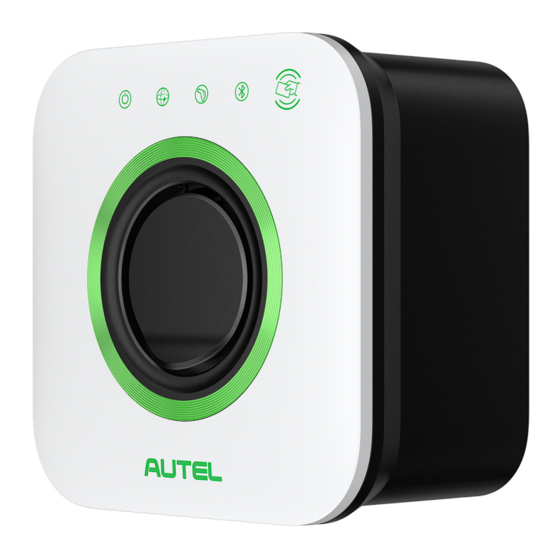
Product Overview 1. LED Indicators (from left to right): Power LED Internet Connection LED Charging LED Bluetooth Connection LED 2. RFID Card Reader 3. Socket 4. Product Label 5. Terminal Block 6. Built-in Spirit Level 7. Back Entry Location for AC Input Cable 8. - Page 9 LED Description Description Solid Green: The charger is on. Not Illuminated: The charger is off. Power LED Flashing Yellow: Data are being transmitted and/or firmware is upgrading. Solid Yellow: Firmware upgrade has failed. Solid Blue: Data transmission has failed; will illuminate green in five seconds. ...
-
Page 10: Specifications
Specifications 3.2.1 Technical Specifications AC Power Output Rating Maximum 7 kW/22 kW Output Current Maximum 32 A 230 V AC, 50 Hz, single-phase AC Power Input Rating 400 V AC, 50 Hz, three-phase 3 wires Input Wiring Scheme ... - Page 11 Bluetooth (Frequency: 2.4 G; Transmit power: 6 dBm) Wi-Fi (Frequency: 2.4 G; Transmit power: 18.5 dBm) Connectivity RFID (Frequency: 13.56 MHz; Transmit power: 2.72 dBuA/m @3 m) Ethernet (Optional) RS485 (Optional) Communications Protocols OCPP 1.6J Mounting Wall-mounted or floor using a pedestal ...
- Page 12 3.2.2 Cable Specifications Cable Type Specification AC Input Cable (Single-phase, 32 A) Cross section: 3 x 6–10 mm Cross section: AC Input Cable (Three-phase, 32 A) TN/TT: 5 x 6–10 mm IT: 4 x 6–10 mm RS485 Cable Cross section: 2 x 0.2–1.5 mm...
-
Page 13: Installation
Installation Before You Begin 4.1.1 Checking the Box Ensure all the items below can be found in the packing box. Some items are packed inside the wirebox. Main Unit (x 1) Wirebox (x 1) Self-tapping Screw Screw (Φ5 x 40) (x 3) (M5 x 10) (x 3) Wall Anchor Self-tapping Screw... - Page 14 4.1.2 Preparing Installation Tools You may need the following tools during installation: Scissors Power Drill Drill Bit (8 mm) Step Bit (30 mm) Phillips Bit (PH2) Marker Tape Measure Wire Stripper Torque Driver Multimeter (2 N·m) Flathead Screwdriver NOTE The tools listed above are excluded from the package. 4.1.3 Location Requirements ...
- Page 15 4.1.4 Cable Entry Options The MaxiCharger AC Compact supports three cable entry options for AC input cables and Ethernet and/or RS485 cable: from the top, from the bottom, and from the back. Depending on AC input cable entry, the Ethernet and/or RS485 cable entry will vary accordingly. The cable entry options are as follows: A —...
-
Page 16: Installing The Maxicharger
Installing the MaxiCharger Step 1 Place the MaxiCharger face down on a table. Hold the main unit (A) and pull up on the strap to release the wirebox (B). Step 2 (Back Entry Only) 1. Use the power drill with a 30 mm step bit to drill two holes at the designated locations. - Page 17 Step 3 1. Place the wirebox against the wall with an appropriate height and level it using the built-in spirit level (A). Recommended height: 850–1150 mm For ADA Accessibility: 700–800 mm 2. Make three marks at the designated location. Remove the wirebox temporarily.
- Page 18 Step 4 Use a pair of scissors to cut two sealing plugs referring to the diagrams to fit the AC input cable and Ethernet cable. Make the holes smaller than the cables to ensure a good fit. Option 1 (AC Input Cable — Top; Ethernet Cable — Bottom) 1.
- Page 19 Option 2 (AC Input Cable — Bottom; Ethernet Cable — Bottom) 1. Route the AC input cable and the Ethernet cable into the wirebox from the bottom. 2. Push the sealing plugs (A) to cling to the entries. 3. Install a strain relief (B) by inserting the two Φ3 x 10 mm self-tapping screws (C).
- Page 20 4.2.1 AC Input Wiring The MaxiCharger supports single-phase and three-phase wiring. Please connect the wires depending on your order. Connect the Wires 1. Strip the wires by 13 mm. 2. Insert the exposed core into the corresponding terminal port. 3. Use a torque driver with a Phillips bit (PH2) to tighten the screws to 2 Nm. Single-phase Wiring Three-phase Wiring...
- Page 21 4.2.2 Connecting the Ethernet Cable Connect the Ethernet cable to the port inside the main unit. 4.2.3 Connecting the RS485 Cable If RS485 communications is needed, the RS485 cable can be routed into the wirebox from the same Ethernet cable entry. 1.
-
Page 22: Completing The Installation
Completing the Installation 1. Attach the main unit onto the wirebox by pushing it forcefully to tightly fit the wirebox. Ensure the internal seal is compressed. 2. Insert the four M5 x 10 screws and fully tighten them using the T25 screwdriver. 3. -
Page 23: Operation
The Autel Charge app displays that your EV is fully charged. — End the charging session via the Autel Charge app or by tapping your RFID card on the RFID card reader again. 2. Remove the charging handle from the charger socket outlet and the EV charge port. -
Page 24: Troubleshooting And Service
Troubleshooting and Service Troubleshooting Table Item Problems Solutions Check whether the QR code on the charger is The charger is successfully consistent with the QR code in the Quick Reference added, but the Bluetooth Guide. If so, make sure that Bluetooth is enabled on connection fails. -
Page 25: Service
If the problem persists, contact customer support. Service If you cannot find solutions to your problems with the aid from the table above, please contact our technical support. AUTEL Website: www.autelenergy.com; www.autelenergy.eu Phone: +49 (0) 89 540299608 (Monday-Friday, 9:00AM-6:00PM Berlin Time) ... -
Page 26: Compliance
Compliance The product is in conformity with the following standards and/or other normative documents: EN 301 489-1 V2.2.3 EN 301 489-3 V2.1.1 EN 301 489-17 V3.2.4 EN 301 489-52 V2.1.1 EN 300 328 V2.2.2 EN 300 330 V2.1.1 EN 301 908-1 V13.1.1 EN 301 908-2 V13.1.1 EN 301 908 -13 V13.1.1 EN 301 511 V12.5.1... -
Page 27: Appendix
Appendix Fault Code List The table below contains the fault codes on the Autel Charge Cloud and their descriptions on the Autel Charge app. Fault Codes Descriptions Mains overvoltage Mains undervoltage Mains over-frequency Mains under-frequency Phase loss Line/Neutral reverse connection... - Page 28 Fault Codes Descriptions 4000000 Output ground fault 8000000 Ground self-test fault 10000000 Microelectronics fault 20000000 Temperature sensor abnormal 40000000 Power System abnormal...
- Page 29 www.autelenergy.com...
Need help?
Do you have a question about the MaxiCharger AC Compact and is the answer not in the manual?
Questions and answers