
Related Manuals for WEG RUW-01


Summary of Contents for WEG RUW-01
- Page 1 Motors | Automation | Energy I Transmission & Distribution | Coatings Remote Unit CANopen RUW-01 Installation Guide, Configuration and Operation...
-
Page 3: Safety Instructions
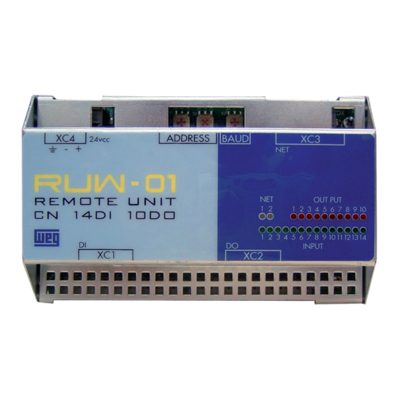
RUW-01 CN14DI10DO: 14 digitals inputs and 10 digitals outputs. It will be referred in this guide for RUW-01.00. RUW-01 CN13DI:i 13 digitals inputs without digitals outputs. It will be referred in this guide for RUW-01.01. OBS: For the both versions will be used RUW-01. -
Page 4: Mechanical Installation
InstalL thea RUW-01 on rail DIN 35 mm, follow figure 1. Figure 1: Setting RUW-01 4.2 ELECTRICAL INSTALLATION The RUW-01 needs external supply of 24 Vdc +/-15 % with capacity of at least 500 mA.. The grounding connection is important. The connections are made through the XC4 connector. - Page 5 CANopen Remote Unit 4.3 NETWORK CONNECTION CANOPEN There is a green LED to indicate that the interface is powered RUW-01 . The communication module CAN has a 5 way connector plug-in (XC3) with the following pinouts: Tabela 1: Pinagem do conector XC3 para interface CAN...
- Page 6 CANopen Remote Unit 4.4 DIGITAL INPUTS CONECTIONS Use cables AWG30-16 for this connection. RUW-01.00: The RUW-01.00 has 14 digital inputs bidiretionais which can be driven through an external 24 Vcc voltage source, as shown in Figure 3 a. - (+) 24 Vcc + (-) (a) XC1: Activation digital inputs RUW-01.00...
-
Page 7: Digital Outputs Connections
+ (-) 24 Vcc - (+) Figura 4: XC2: Connection digital outputs RUW-01.00 5 CONFIGURATION The RUW-01 configuration is made by hex keys with the following functions: S1 and S2: CANopen network address configuration. S3: Selecting the communication rate. - Page 8 The CANopen´s address is configured with two hexagonal keys S1 and S2 as shown in figure 6. This address is used to identify the RUW-01 in the CANopen network. It is necessary that each network equipament has a different address form the others.
- Page 9 This Rate must be the same for all connected equipaments in the network. The RUW-01 present the apresenta hexadecimal key S3 for selection of the communication ratem as shown in figure 6. The communication rate options are: ...
-
Page 10: Communication Diagnostic
CANopen Remote Unit 6 DIAGNOSTIC The RUW-01 features a dianostic by LEDs that indicate he status of each digital input or output and the communication status. Communication LEDs Input LEDs Figure 7: LEDs communication RUW-01 6.1 COMMUNICATION DIAGNOSTIC The communication features 2 LEDs: CAN (NET 1) e ERROR (NET 2). - Page 11 CANopen network, usually associate with problems in BUS OFF Error INSTALATION or wrong configuration of communication rate. It is necessary turn on the RUW-01 again. Erro de BUS Indica que a interface CAN não possui alimentação Vermelho POWER OFF entre os pinos 1 e 5 do conector ...
- Page 12 CANopen Remote Unit ms ms LED flashes 50 ms LED flashes 200 ms 1000 LED flashes once per second 1000 LED flashes twice per second Figure 8: Diagram for signaling behavior RUW-01 English...
Need help?
Do you have a question about the RUW-01 and is the answer not in the manual?
Questions and answers