Table of Contents
Advertisement
Quick Start
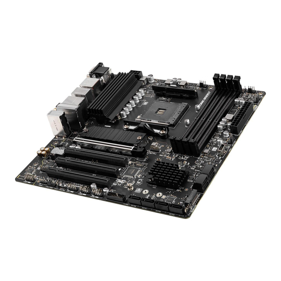
Thank you for purchasing the MSI®
PRO B550M-VC WIFI
motherboard. This Quick
Start section provides demonstration diagrams about how to install your computer.
Some of the installations also provide video demonstrations. Please link to the URL to
watch it with the web browser on your phone or tablet. You may have even link to the
URL by scanning the QR code.
Preparing Tools and Components
AMD® AM4 CPU
CPU Fan
Chassis
DDR4 Memory
Power Supply Unit
Graphics Card
Thermal Paste
SATA Hard Disk Drive
SATA DVD Drive
A Package of Screws
Phillips Screwdriver
1
Quick Start
Advertisement
Table of Contents

Related Manuals for MSI PRO B550M-VC WIFI


Summary of Contents for MSI PRO B550M-VC WIFI
-
Page 1: Quick Start
Quick Start Thank you for purchasing the MSI® PRO B550M-VC WIFI motherboard. This Quick Start section provides demonstration diagrams about how to install your computer. Some of the installations also provide video demonstrations. Please link to the URL to watch it with the web browser on your phone or tablet. You may have even link to the URL by scanning the QR code. -
Page 2: Safety Information
Safety Information ∙ The components included in this package are prone to damage from electrostatic discharge (ESD). Please adhere to the following instructions to ensure successful computer assembly. ∙ Ensure that all components are securely connected. Loose connections may cause the computer to not recognize a component or fail to start. -
Page 3: Installing A Processor
Installing a Processor https://youtu.be/Xv89nhFk1vc Quick Start... - Page 4 ⚠ Important If you are installing the screw-type CPU heatsink, please follow the figure below to remove the retention module first and then install the heatsink. Quick Start...
-
Page 5: Installing Ddr4 Memory
Installing DDR4 memory http://youtu.be/T03aDrJPyQs DIMMA1 DIMMA2 DIMMA2 DIMMA2 DIMMB1 DIMMB2 DIMMB2 Quick Start... -
Page 6: Connecting The Front Panel Header
Connecting the Front Panel Header http://youtu.be/DPELIdVNZUI Power LED Power Switch JFP1 Reserved HDD LED Reset Switch HDD LED + Power LED + HDD LED - Power LED - Reset Switch Power Switch JFP1 Reset Switch Power Switch Reserved No Pin HDD LED - HDD LED HDD LED +... -
Page 7: Installing The Motherboard
Installing the Motherboard https://youtu.be/wWI6Qt51Wnc Torque: 3 kgf·cm* BAT1 *3 kgf·cm = 0.3 N·m = 2.6 lbf·in Quick Start... -
Page 8: Connecting The Power Connectors
Connecting the Power Connectors http://youtu.be/gkDYyR_83I4 ATX_PWR1 CPU_PWR1 Quick Start... -
Page 9: Installing Sata Drives
Installing SATA Drives http://youtu.be/RZsMpqxythc Quick Start... -
Page 10: Installing A Graphics Card
Installing a Graphics Card http://youtu.be/mG0GZpr9w_A Quick Start... -
Page 11: Connecting Peripheral Devices
Connecting Peripheral Devices Quick Start... -
Page 12: Power On
Power On Quick Start... -
Page 13: Table Of Contents
Contents Quick Start ......................1 Preparing Tools and Components................1 Safety Information ....................2 Installing a Processor .................... 3 Installing DDR4 memory ..................5 Connecting the Front Panel Header ..............6 Installing the Motherboard ..................7 Connecting the Power Connectors ................ 8 Installing SATA Drives .................... - Page 14 EZ Debug LED ....................... 41 LED_SW1: EZ LED Control ................... 41 Installing OS, Drivers & MSI Center ..............42 Installing Windows® 10 ..................42 Installing Drivers ....................42 MSI Center ......................42 UEFI BIOS ......................43 BIOS Setup ......................44 Entering BIOS Setup .....................
-
Page 15: Specifications
∙ Supports non-ECC UDIMM memory ∙ Supports ECC UDIMM memory ∙ Supports un-buffered memory * Please refer www.msi.com for more information on compatible memory. ∙ 1x PCIe 3.0/ 4.0 x16 slot (PCI_E1)* Expansion Slot ∙ 3x PCIe 3.0 x16 slots, support PCIe x1 speed * The supported specification depends on installed processor. - Page 16 Continued from previous page ASMedia AM1064 Chipset ∙ 4x SATA 6Gb/s ports AMD B550 Chipset ∙ 4x SATA 6Gb/s ports ∙ 2x M.2 slots (Key M) ▪ M2_1 slot (from AMD processor) Storage ▫ Supports PCIe 4.0/ 3.0 x4 * ▫...
- Page 17 Continued from previous page AMD Wi-Fi 6E ∙ The Wireless module is pre-installed in the M.2 (Key-E) slot ∙ Supports MU-MIMO TX/RX ∙ Supports 20MHz, 40MHz, 80MHz,160MHz bandwidth in Wireless LAN & 2.4GHz/ 5GHz or 6GHz* bands Bluetooth® ∙ Supports 802.11 a/ b/ g/ n/ ac/ ax ∙...
- Page 18 ∙ UEFI AMI BIOS BIOS Features ∙ ACPI 6.0, SMBIOS 2.8 ∙ Multi-language ∙ Drivers ∙ MSI Center Software ∙ CPU-Z MSI GAMING ∙ Google Chrome™, Google Toolbar, Google Drive ∙ Norton™ Internet Security Solution Continued on next page Specifications...
- Page 19 ∙ Live Update MSI Center Features ∙ Hardware Monitor ∙ Super Charger ∙ Speed Up ∙ Smart Image Finder ∙ MSI Companion ∙ Audio ▪ Audio Boost ∙ Network ▪ Intel WiFi ∙ Cooling ▪ Pump Fan ▪ Smart Fan Control ∙...
-
Page 20: Package Contents
Package contents Please check the contents of your motherboard package. It should contain: Motherboard PRO B550M-VC WIFI SATA 6G cables Cable (2 cables/pack) Wi-Fi antenna M.2 screws (3 pcs./pack) Accessories Case badge Product registration card Application Driver DVD Documentation Quick installation guide ⚠... -
Page 21: Block Diagram
Block Diagram 2 Channel DDR4 Memory Processor 1x M.2 PCI Express Bus 2x USB 3.2 Gen1 1x M.2 +2x USB 3.2 Gen2 PCIE Front Audio Jacks Realtek ALC892/ 4x SATA 6Gb/s ALC897 Rear Audio Jacks Asmedia 4x SATA 6Gb/s AM1064 NUVOTON 6687 Chipset... -
Page 22: Rear I/O Panel
Rear I/O Panel Wi-Fi Antenna PS/2 Combo connectors Line-In USB 3.2 Gen 2 1 Gbps LAN (10Gbps) Type-A Mic-In USB 2.0 Flash BIOS Button Type-A Line-Out DisplayPort Flash BIOS USB 3.2 Gen 1 Port (5Gbps) Type-A ∙ Flash BIOS Port/ Button - Please refer to page 46 for Updating BIOS with Flash BIOS Button. - Page 23 ∙ Device Selection - allows you to select a audio output source to change the related options. The check sign indicates the devices as default. ∙ Application Enhancement - the array of options will provide you a complete guidance of anticipated sound effect for both output and input device. ∙...
- Page 24 Installing antennas 1. Screw the antennas tight to the antenna connectors as shown below. 2. Orient the antennas. Rear I/O Panel...
-
Page 25: Overview Of Components
Overview of Components Processor Socket DIMMA1 DIMMA2 DIMMB1 CPU_FAN1 CPU_PWR1 DIMMB2 PUMP_FAN1 JRAINBOW1 SYS_FAN1 ATX_PWR1 JTPM1 SYS_FAN2 JUSB1 M2_1 PCI_E1 SATA▼1▲2 PCI_E2 BAT1 JBAT1 SATA▼3▲4 PCI_E3 M2_2 PCI_E4 JFP2 JAUD1 JRGB1 SATA5 SYS_FAN3 SATA6 JCI1 SATA7 LED_SW1 SATA8 JFP1 JUSB4 JUSB2 JUSB3 Overview of Components... - Page 26 Component Contents Port Name Port Type Page CPU_FAN1, PUMP_FAN1, Fan Connectors SYS_FAN1~3 CPU_PWR1, ATX_PWR1 Power Connectors DIMMA1, DIMMA2, DIMMB1, DIMM Slots DIMMB2 JAUD1 Front Audio Connector JBAT1 Clear CMOS Jumper JCI1 Chassis Intrusion Connector JFP1, JFP2 Front Panel Connectors JRAINBOW1 Addressable RGB LED connector JRGB1 RGB LED connector...
-
Page 27: Processor Socket
This motherboard is designed to support overclocking. Before attempting to ∙ overclock, please make sure that all other system components can tolerate overclocking. Any attempt to operate beyond product specifications is not recommended. MSI does not guarantee the damages or risks caused by inadequate ® operation beyond product specifications. -
Page 28: Dimm Slots
It is recommended to use a more efficient memory cooling system for full DIMMs installation or overclocking. The stability and compatibility of installed memory module depend on installed CPU ∙ and devices when overclocking. Please refer www.msi.com for more information on compatible memory. ∙ Overview of Components... -
Page 29: Pci_E1~4: Pcie Expansion Slots
PCIe 3.0 x1 (PCH) ⚠ Important If you install a large and heavy graphics card, you need to use a tool such as MSI ∙ Gaming Series Graphics Card Bolster to support its weight to prevent deformation of the slot. -
Page 30: M2_1~2: M.2 Slots (Key M)
M2_1~2: M.2 Slots (Key M) ⚽ Video Demonstration Watch the video to learn how to Install M.2 module. http://youtu.be/JCTFABytrYA M2_1 M2_2 M2_1 slot installation 1. Loosen the screws of M.2 SHIELD FROZR heatsink. 2. Remove the M.2 SHIELD FROZR and remove the protective films from the thermal pads. - Page 31 3. Move and fasten the M.2 standoff to the appropriate position for your M.2 SSD, or remove the M.2 standoff if your M.2 SSD length is same as the length of M.2 heatsink to avoid damage to the M.2 SSD. 4.
-
Page 32: Jfp1, Jfp2: Front Panel Connectors
JFP1, JFP2: Front Panel Connectors These connectors connect to the switches and LEDs on the front panel. Power LED Power Switch JFP1 Reserved HDD LED Reset Switch HDD LED + Power LED + HDD LED - Power LED - Reset Switch Power Switch Reset Switch Power Switch... -
Page 33: Cpu_Pwr1, Atx_Pwr1: Power Connectors
CPU_PWR1, ATX_PWR1: Power Connectors These connectors allow you to connect an ATX power supply. CPU_PWR1 Ground +12V Ground +12V Ground +12V Ground +12V +3.3V +3.3V +3.3V -12V Ground Ground PS-ON# Ground Ground Ground ATX_PWR1 Ground Ground PWR OK 5VSB +12V +12V +3.3V Ground... -
Page 34: Jusb1: Usb 3.2 Gen 1 5Gbps Type-C Connector
JUSB1: USB 3.2 Gen 1 5Gbps Type-C Connector This connector allows you to connect USB 3.2 Gen 1 5Gbps Type-C connector on the front panel. The connector possesses a foolproof design. When you connect the cable, be sure to connect it with the corresponding orientation. USB Type-C Cable JUSB1 USB Type-C port on... -
Page 35: Jusb3~4: Usb 2.0 Connectors
In order to recharge your iPad,iPhone and iPod through USB ports, please install ∙ MSI Center utility. JTPM1: TPM Module Connector This connector is for TPM (Trusted Platform Module). Please refer to the TPM security platform manual for more details and usages. -
Page 36: Cpu_Fan1, Pump_Fan1, Sys_Fan1~3: Fan Connectors
CPU_FAN1, PUMP_FAN1, SYS_FAN1~3: Fan Connectors Fan connectors can be classified as PWM (Pulse Width Modulation) Mode or DC Mode. PWM Mode fan connectors provide constant 12V output and adjust fan speed with speed control signal. DC Mode fan connectors control fan speed by changing voltage. The auto mode fan connectors can automatically detect PWM and DC mode. -
Page 37: Jci1: Chassis Intrusion Connector
JCI1: Chassis Intrusion Connector This connector allows you to connect the chassis intrusion switch cable. Normal Trigger the chassis (default) intrusion event Using chassis intrusion detector 1. Connect the JCI1 connector to the chassis intrusion switch/ sensor on the chassis. 2. -
Page 38: Jbat1: Clear Cmos (Reset Bios) Jumper
JBAT1: Clear CMOS (Reset BIOS) Jumper There is CMOS memory onboard that is external powered from a battery located on the motherboard to save system configuration data. If you want to clear the system configuration, set the jumpers to clear the CMOS memory. Keep Data Clear CMOS/ (default) -
Page 39: Jrgb1: Rgb Led Connector
(12V/G/R/B) with the maximum power rating of 3A (12V). Always turn off the power supply and unplug the power cord from the power outlet ∙ before installing or removing the RGB LED strip. ∙ Please use MSI’s software to control the extended LED strip. Overview of Components... -
Page 40: Jrainbow1: Addressable Rgb Led Connector
(5V). In the case of 20% brightness, the connector supports up to 200 LEDs. ∙ Always turn off the power supply and unplug the power cord from the power outlet before installing or removing the RGB LED strip. Please use MSI’s software to control the extended LED strip. ∙ Overview of Components... -
Page 41: Ez Debug Led
EZ Debug LED These LEDs indicate the debug status of the motherboard. CPU - indicates CPU is not detected or fail. DRAM - indicates DRAM is not detected or fail. VGA - indicates GPU/ PCIE/ M.2 device is not detected or fail. -
Page 42: Installing Os, Drivers & Msi Center
MSI Center is an application that helps you easily optimize game settings and smoothly use content creation softwares. It also allows you to control and synchronize LED light effects on PCs and other MSI products. With MSI Center, you can customize ideal modes, monitor system performance, and adjust fan speed. -
Page 43: Uefi Bios
UEFI has many new functions and advantages that traditional BIOS cannot achieve, and it will completely replace BIOS in the future. The MSI UEFI BIOS uses UEFI as the default boot mode to take full advantage of the new chipset’s capabilities. -
Page 44: Bios Setup
BIOS Setup The default settings offer the optimal performance for system stability in normal conditions. You should always keep the default settings to avoid possible system damage or failure booting unless you are familiar with BIOS. ⚠ Important BIOS items are continuously update for better system performance. Therefore, the ∙... -
Page 45: Resetting Bios
Updating BIOS Updating BIOS with M-FLASH Before updating: Please download the latest BIOS file that matches your motherboard model from MSI website. And then save the BIOS file into the USB flash drive. Updating BIOS: 1. Insert the USB flash drive that contains the update file into the USB port. - Page 46 1. Please download the latest BIOS file that matches your motherboard model from the MSI® website. 2. Rename the BIOS file to MSI.ROM, and save it to the root of your USB flash drive. 3. Connect the power supply to CPU_PWR1 and ATX_PWR1. (No need to install CPU and memory.)
-
Page 47: Ez Mode
EZ Mode At EZ mode, it provides the basic system information and allows you to configure the basic setting. To configure the advanced BIOS settings, please enter the Advanced Mode by pressing the Setup Mode switch or F7 function key. Screenshot A-XMP Profile Setup Mode switch... - Page 48 ∙ System information - shows the CPU/ DDR speed, CPU/ MB temperature, MB/ CPU type, memory size, CPU/ DDR voltage, BIOS version and build date. ∙ Boot device priority bar - you can move the device icons to change the boot priority. The boot priority from high to low is left to right.
- Page 49 ▪ To add a BIOS item to a favorite menu 1. Select a BIOS item not only on BIOS menu but also on search page. 2. Right-click or press F2 key. 3. Choose a favorite page and click on OK. ▪...
-
Page 50: Advanced Mode
Advanced Mode Press Setup Mode switch or F7 function key can switch between EZ Mode and Advanced Mode in BIOS setup. BIOS menu BIOS menu selection selection Menu display ∙ BIOS menu selection - the following options are available: ▪ SETTINGS - allows you to specify the parameters for chipset and boot devices. ▪... -
Page 51: Settings Menu
SETTINGS Menu This menu allows you to specify the parameters for system, chipset and boot devices. ▶ System Status sub-menu The System Status sub-menu allows you to set the system clock and view system information. ▶ System Date Sets the system date. Use tab key to switch between date elements. The format is <day>... - Page 52 ▶ Integrated Graphics Configuration sub-menu (optional) Adjusts integrated graphics settings for optimum system. This sub-menu is only available when using the CPU which integrate with IGP. ▶ USB Configuration sub-menu Sets the onboard USB controller and device function. Press Enter to enter the sub-menu.
-
Page 53: Oc Menu
OC Menu This menu allows you to configure the frequencies and voltages for overclocking. Please note that, higher frequency and voltage may benefit overclocking capability but cause system un-stability. ⚠ Important Overclocking your PC manually is only recommended for advanced users. ∙... - Page 54 ▶ FCLK Frequency [Auto] Sets the FCLK frequency (Internal Data Fabric clock of DRAM). Please note the overclocking behavior is not guaranteed. ▶ UCLK DIV1 Mode [Auto] Sets UCLK (Internal memory controller clock) mode. ▶ Memory Try It ! [Disabled] It can improve memory compatibility or performance by choosing optimized memory preset.
- Page 55 ▶ Memory Changed Detect [Enabled]* Enables or disables the system to issue a warning message during boot when the memory has been replaced. [Enabled] The system will issue a warning message during boot and then you have to load the default settings for new devices. [Disabled] Disables this function and keeps the current BIOS settings.
-
Page 56: M-Flash Menu
M-FLASH provides the way to update BIOS with a USB flash drive. Please download the latest BIOS file that matches your motherboard model from MSI website, save the BIOS file into your USB flash drive. And then follow the steps below to update BIOS. -
Page 57: Oc Profile Menu
OC PROFILE Menu ▶ Overclocking Profile 1/ 2/ 3/ 4/ 5/ 6 Overclocking Profile 1/ 2/ 3/ 4/ 5/ 6 management. Press Enter to enter the sub-menu. ▶ Set Name for Overclocking Profile 1/ 2/ 3/ 4/ 5/ 6 Name the current overclocking profile. ▶... -
Page 58: Hardware Monitor Menu
HARDWARE MONITOR Menu This menu allows you to adjust the fan speed manually and monitor CPU/ system voltage. Select a temperature curve line (white) to be showed in Fan operating window Select a fan to be configured Select a fan mode for target fan Click to enable the Smart Fan Smart Fan duty... - Page 59 Adjusting fans 1. Selects a fan that you want to adjust and to display the fan duty curve line (yellow) in fan operating windows. 2. Click and drag the duty points to adjust the fan speed. Select a fan to be adjusted Duty points ⚠...
-
Page 60: Amd Raid Configuration
AMD RAID Configuration The following are the RAID levels supported by RAIDXpert2. RAID 0 (Striping) breaks the data into blocks which are written to separate hard drives. Spreading the hard drive I/O load across independent channels greatly improves I/O performance. RAID 1 (Mirroring) provides data redundancy by mirroring data between the hard drives and provides enhanced read performance. -
Page 61: Initializing Disks
Initializing Disks New disks and legacy disks must be initialized before they can be used to create an AMD-RAID array. Initialization writes AMD-RAID configuration information (metadata) to a disk. ⚠ Important ∙ If a disk is part of an AMD-RAID array, the disk cannot be selected for initialization. To initial the disk anyway, delete the AMD-RAID array. -
Page 62: Creating Arrays
Creating Arrays Arrays can be created after the disks are initialized. ⚠ Important For redundant arrays, the Create process is not started until after the operating ∙ system and AMD-RAID OS drivers have been installed and the system has booted to the operating system. -
Page 63: Deleting Arrays
Deleting Arrays ⚠ Important Deleting an array permanently destroys all data that is on the array. This action ∙ cannot be undone and it is very unlikely that the data can be recovered. ∙ Do not delete the first array listed in the Arrays section, if it is the AMD-RAID bootable array. -
Page 64: Installing Raid Driver
2. When prompted, insert the USB flash drive with AMD RAID Drivers and then click Browse. ▪ To make an AMD RAID Drivers USB flash drive. Insert the MSI Driver Disc into the optical drive. Copy all the contents in \\Storage\AMD\ 3. -
Page 65: Troubleshooting
Troubleshooting Lost BIOS password Before sending the motherboard for RMA repair, try to go over troubleshooting ∙ Clear the CMOS, but that will cause guide first to see if your got similar you to lose all customized settings in the symptoms as mentioned below. - Page 66 제조년월: 2022년 disposing of their end-of-life products. R-R-MSI-30-7C95 제조자 및 제조국가: MSI/중국 • Visit the MSI website and locate a nearby distributor for further recycling information. • Users may also reach us at gpcontdev@msi.com for information regarding proper Disposal, Take-back, Recycling, and Disassembly of MSI products.
- Page 67 MSI will comply with the product take establecido por el ayuntamiento de su localidad o back requirements at the end of life of MSI-branded entregar a una empresa autorizada para la recogida de products that are sold into the EU.
- Page 68 MSI si adeguerà a tale Direttiva indicated in instructions specific to the product. ritirando tutti i prodotti marchiati MSI che sono stati venduti all’interno dell’Unione Europea alla fine del...
- Page 69 Copyright © 2022 All rights reserved. contact your place of purchase or local distributor. The MSI logo used is a registered trademark of Alternatively, please try the following help resources Micro-Star Int’l Co., Ltd. All other marks and names for further guidance.
Need help?
Do you have a question about the PRO B550M-VC WIFI and is the answer not in the manual?
Questions and answers