Table of Contents
Advertisement
Quick Links
S
TREAM
ADCP G
Information included herein is controlled by the Export Administration Regulations (EAR) and may
require an export license, license exception or other approval from the appropriate U.S. Government
agency before being exported from the United States or provided to any foreign person. Diversion
contrary to U.S. law is prohibited.
P
RO
UIDE
P/N 95B-6003-00 (April 2022)
© 2022 Teledyne RD Instruments, Inc. All rights reserved.
www.teledynemarine.com/rdi
Advertisement
Table of Contents

Related Manuals for Teledyne STREAMPRO


Summary of Contents for Teledyne STREAMPRO
- Page 1 ADCP G UIDE P/N 95B-6003-00 (April 2022) © 2022 Teledyne RD Instruments, Inc. All rights reserved. Information included herein is controlled by the Export Administration Regulations (EAR) and may www.teledynemarine.com/rdi require an export license, license exception or other approval from the appropriate U.S. Government agency before being exported from the United States or provided to any foreign person.
- Page 2 Page ii EAR-Controlled Technology Subject to Restrictions Contained on the Cover Page.
-
Page 3: Table Of Contents
Spare Parts ..............................17 Replacing Batteries ............................17 Periodic Maintenance ..........................19 Calibration Items ..........................19 Visual Inspection of the StreamPro ...................... 20 Removing Biofouling ..........................21 Replacing the Battery Compartment O-Ring ..................22 Replacing the Electronic Housing O-Ring ..................... 23 Transducer Cable Connector Repair ..................... - Page 4 Q/Z 1250 Power Trimaran ......................4 Figure 4. SXBlue II GPS with Mounting Kit ....................5 Figure 5. StreamPro ADCP Assembly – Boom in Extended Position ............8 Page iv EAR-Controlled Technology Subject to Restrictions Contained on the Cover Page.
- Page 5 Figure 6. StreamPro ADCP Assembly – Boom in in-hull Position ............... 8 Figure 7. M6 Standoff Bolt on Electronic Housing Cover Plate ..............9 Figure 8. In-Hull Position ......................... 10 Figure 9. Extended Position........................11 Figure 10. Forward Mark on Transducer ....................12 Figure 11.
- Page 6 • Updated inventory section April 2012 • Changed name of manual from StreamPro ADCP Operation Manual to StreamPro ADCP Guide. • Update fonts and styles used throughout the manual. Page vi EAR-Controlled Technology Subject to Restrictions Contained on the Cover Page.
- Page 7 Corrected Velocity Profiling Specifications: The 1 Cell start specification and velocity range was corrected and the wording revised to be consistent with the StreamPro brochure (see ICN 133). • Corrected EX command default (with compass) from EX10xx0 to EX101x1 (See ICN 136).
- Page 8 (this can take up to 24 hours). Once you have secured an account, use the Teledyne Marine software portal to access this data with your unique username and password.
- Page 9 SED IN THIS ANUAL Conventions used in the StreamPro documentation have been established to help you learn how to use the StreamPro quickly and easily. Software menu items are printed in bold: File menu, Collect Data. Items that need to be typed by the user or keys to press will be shown as F1.
- Page 10 OTES Page x EAR-Controlled Technology Subject to Restrictions Contained on the Cover Page.
-
Page 11: Chapter 1 - A T A Glance
P/N 95B-6003-00 (April 2022) Chapter LANCE This chapter includes: • StreamPro ADCP overview • Inventory of parts • StreamPro ADCP options • StreamPro ADCP assembly • Caring for your StreamPro ADCP Page 1 EAR-Controlled Technology Subject to Restrictions Contained on the Cover Page. -
Page 12: Streampro Adcp Overview
P/N 95B-6003-00 (April 2022) StreamPro ADCP Guide StreamPro ADCP Overview The StreamPro ADCP is designed to measure real-time velocity and discharge measurements in shallow streams. The StreamPro system consists of a transducer, electronics housing, tethered trimaran, and soft- ware. Transducer Assembly –... -
Page 13: Inventory
Although this is its primary func- tion, it can be used for general coastal survey applications. TRDI Toolz Software Utility and testing software that can be used to test the StreamPro. Section-by-Section (SxS) Pro is a stationary ADCP discharge data collec- SxS Pro Software... -
Page 14: Streampro Adcp Options
StreamPro ADCP Options The StreamPro has several options: Riverboat SP – The Oceanscience Riverboat SP provides a stable platform for the StreamPro ADCP in high- flow water. The standard StreamPro tethered trimaran works well in flows to 1.5 meters/second. The Riverboat SP can be used in flows to approximately 4.5 meters/second (condition... -
Page 15: Figure 4. Sxblue Ii Gps With Mounting Kit
– The GPS mounting kit is designed to hold the GENEQ unit to either the standard StreamPro tethered trimaran or the Riverboat SP. The mounting kit is available from TRDI. The SXBlue II GPS system may be purchased separately from TRDI or other sources. -
Page 16: Streampro Adcp Care
Loose, missing, stripped hard- Read the Maintenance section for details on StreamPro assembly. ware, or damaged O-rings can lead to water ingress and damage to the StreamPro ADCP. • Do not connect or disconnect the transducer cable with power applied. When you connect the The connector pins may become pitted and cable with power applied, you may see a small spark. -
Page 17: Chapter 2 - Stream Pro Adcp Assembly
• Attaching the electronics housing to the tethered trimaran • Attaching and removing the solar shield • Assembling the boom arm • Adjusting the towing harness angle • Storing the StreamPro ADCP Page 7 EAR-Controlled Technology Subject to Restrictions Contained on the Cover Page. -
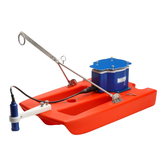
Page 18: Figure 5. Streampro Adcp Assembly - Boom In Extended Position
P/N 95B-6003-00 (April 2022) StreamPro ADCP Guide This section shows how to assemble the StreamPro tethered trimaran and attach the transducer to the deployment boom. Figure 5. StreamPro ADCP Assembly – Boom in Extended Position Figure 6. StreamPro ADCP Assembly – Boom in in-hull Position The StreamPro’s compass is located in the Electronic Chassis. -
Page 19: Attaching The Electronic Housing
StreamPro ADCP Guide P/N 95B-6003-00 (April 2022) Attaching the Electronic Housing To attach the electronic housing to the tethered trimaran: 1. Attach the mounting plates to the electronic housing using the four flat head screws. 2. Attach the mounting plates to the tethered trimaran using the four flat head screws. The I/O cable connector should be facing toward the front of the tethered trimaran. -
Page 20: Assembling The Boom
P/N 95B-6003-00 (April 2022) StreamPro ADCP Guide Assembling the Boom To attach the boom to the tethered trimaran: 1. Loosen the clamp thumbscrew on the boom. Feed the transducer cable up through the bottom of the clamp. 2. Attach the transducer cable to the electronics housing. To make the connection, remove the pro- tective cap from the receptacle on the electronics housing. -
Page 21: Adjusting The Streampro Transducer
Rotate the transducer so that Beam 3 is forward and at a 45 degree angle to the tethered trimaran. The StreamPro’s compass is located in the Electronic Chassis. Beam 3 orientation is toward the power switch and the connector should be facing forward if the Electronic Chassis is mounted on a different tethered trimaran/boat. -
Page 22: Figure 10. Forward Mark On Transducer
P/N 95B-6003-00 (April 2022) StreamPro ADCP Guide Forward Arrow Figure 10. Forward Mark on Transducer Make sure the arrow is pointing to the front of the tethered trimaran to ensure that Beam 3 is pointed forward and at the 45-degrees angle for both the in-hull and extended positions. -
Page 23: Adjusting The Towing Harness Angle
The towing harness may be pre-installed. Storing the StreamPro ADCP Store the StreamPro in the original shipping crate whenever possible: 1. Remove the batteries from the battery holder. 2. Remove the transducer from the boom arm and disconnect the transducer cable. Place the protec- tive cap on the electronic housing transducer cable connector. - Page 24 P/N 95B-6003-00 (April 2022) StreamPro ADCP Guide Always dry the StreamPro before placing it in the storage case to avoid fungus or mold growth. Do not store the StreamPro ADCP in wet or damp locations. Do not leave the batteries inside the StreamPro ADCP for extended periods. The batteries may leak, causing damage to the electronics.
-
Page 25: Stream Pro Adcp Maintenance
StreamPro ADCP Guide P/N 95B-6003-00 (April 2022) Chapter ADCP M TREAM AINTENANCE This chapter includes: • StreamPro ADCP Parts location • Visual inspection • Replacing the batteries • Periodic maintenance Page 15 EAR-Controlled Technology Subject to Restrictions Contained on the Cover Page. -
Page 26: Streampro Adcp Parts Locations
P/N 95B-6003-00 (April 2022) StreamPro ADCP Guide StreamPro ADCP Parts Locations Figure 14. StreamPro ADCP Electronic Housing Assembly Page 16 EAR-Controlled Technology Subject to Restrictions Contained on the Cover Page. -
Page 27: Spare Parts
Store the batteries in a cool, dry location (0 to 21 degrees C). When using eight AA cells, check that the battery voltage is above 11.5 Volts DC. StreamPro ADCPs will work at 11.5 volts; however, batteries with voltages below 11.5 volts are at or near their end of life and are approaching uselessness. -
Page 28: Figure 15. Streampro Battery Replacement
P/N 95B-6003-00 (April 2022) StreamPro ADCP Guide 5. Remove all of the old batteries. 6. Replace with eight new Alkaline AA batteries. Match the battery polarity as shown on the battery holder. 7. Observe that the inside of the battery housing area is dry and clean. Thoroughly clean both the cover plate and the blue surface area around the O-ring. -
Page 29: Periodic Maintenance
Factory Maintenance Service. At the same time, TRDI will make any necessary upgrades to boards, as- semblies, and firmware. With proper care, general maintenance, and this routine service period, you will ensure that the StreamPro ADCP lasts for a minimum of 10 years with no loss in performance. Calibration Items... -
Page 30: Visual Inspection Of The Streampro
StreamPro ADCP Guide Visual Inspection of the StreamPro Inspect the StreamPro using Table 2 and Figure 1. If you find any discrepancies, call TRDI for instruc- tions. Repair of the transducer faces or connector should only be done by TRDI. -
Page 31: Removing Biofouling
The cable connector is keyed to ensure proper connection. The protective cap should be installed on the connector any time the cable is removed from the electronic housing. Use the cap when the StreamPro is in storage or is being handled. Removing Biofouling Before storing or shipping the StreamPro, remove all foreign matter and biofouling. -
Page 32: Replacing The Battery Compartment O-Ring
Defects must be less than 0.1 mm (0.004 in.). If the O-ring appears compressed from prior use, replace it. Weak or damaged O-rings will cause the StreamPro to flood. 5. Clean and inspect the O-ring groove and the surface around the O-ring. Be sure the groove is free of foreign matter, scratches, indentations, corrosion, and pitting. -
Page 33: Replacing The Electronic Housing O-Ring
The electronic housing O-Ring should be replaced whenever the electronic housing is opened or every three years. Follow all the steps for the electronic housing O-Ring replacement. The watertight integrity of the StreamPro depends on this seal. To Remove the Cover Plate: 1. Turn the power switch OFF. - Page 34 Check that no wires or any other object is pinched between the cover and the housing. If the O-ring is not in the groove or if a wire or other object is pinched, the StreamPro will flood. 2. Examine the housing assembly standoff bolts, split washer, and flat washers (M6) for corrosion: replace if necessary.
-
Page 35: Transducer Cable Connector Repair
The locking teeth on the transducer cable coupling ring can become stripped, making it difficult or impos- sible to make a watertight connection to the StreamPro electronic housing. Spare coupling rings are avail- able for purchase: AMP/Tyco Electronics, Coupling Ring Shell size 17, part number 925485-1 (CPC- KUPPLUNGSRING). - Page 36 P/N 95B-6003-00 (April 2022) StreamPro ADCP Guide OTES Page 26 EAR-Controlled Technology Subject to Restrictions Contained on the Cover Page.
-
Page 37: Returning
StreamPro ADCP Guide P/N 95B-6003-00 (April 2022) Chapter TRDI ETURNING YSTEMS TO ERVICE This chapter includes • How to pack and ship the ADCP • How to get a RMA number • Where to send your ADCP for repair Page 27... -
Page 38: Shipping The Adcp
TRDI strongly recommends using the original shipping crate whenever transporting the StreamPro ADCP. If you need to ship the StreamPro ADCP, use the original shipping crate whenever possible. If the original packaging material is unavailable or unserviceable, additional material is available through TRDI. -
Page 39: Returning Systems To The Trdi Factory
When shipping the system to TRDI from either inside or outside the United States, the following instruc- tions will help ensure the StreamPro ADCP arrives with the minimum possible delay. Any deviation from these instructions increases the potential for delay. -
Page 40: Returning Systems To Trdi Europe Factory
Carrier route and flight numbers for all flights the package will take Returning Systems to TRDI Europe Factory When shipping the system to TRDI Europe, the following instructions will help ensure the StreamPro ADCP arrives with the minimum possible delay. Any deviation from these instructions increases the po- tential for delay. - Page 41 StreamPro ADCP Guide P/N 95B-6003-00 (April 2022) Step 4 - Include Proper Customs Documentation The Customs statement must be completed. It should be accurate and truthfully contain the following in- formation. • Contents of the shipment • Value • Purpose of shipment (example: “American made goods returned for repair”) •...
- Page 42 P/N 95B-6003-00 (April 2022) StreamPro ADCP Guide OTES Page 32 EAR-Controlled Technology Subject to Restrictions Contained on the Cover Page.
-
Page 43: Chapter 5 - Stream Pro Adcp Commands
StreamPro ADCP Guide P/N 95B-6003-00 (April 2022) Chapter ADCP C TREAM OMMANDS This chapter includes: • Data communication and command format • Command descriptions Page 33 EAR-Controlled Technology Subject to Restrictions Contained on the Cover Page. -
Page 44: Data Communication And Command Format
TRDI’s BBTalk. The StreamPro communicates with the computer through the Bluetooth interface. Immediately after you apply power to the StreamPro, it enters the standby mode. Send a = = = signal us- ing BBTalk. When the StreamPro receives a = = = signal, it responds with a wake-up message similar to the one shown below. -
Page 45: Data Output Processing
P/N 95B-6003-00 (April 2022) Data Output Processing After the StreamPro completes a data collection cycle, it sends a block of data called a data ensemble. A data ensemble consists of the data collected and averaged during the ensemble interval. A data ensemble can contain header, leader, velocity, correlation magnitude, echo intensity, and percent good. -
Page 46: Display Banner
Lists the special firmware upgrades that are installed. Format Recommended Setting. Use as needed. Description Lists special features that are installed. See the StreamPro Software User's Guide for in- formation on how to install additional capability in your StreamPro. Examples See below. -
Page 47: Control System Commands
Use CS to tell the StreamPro to start pinging its transducers and collecting data as pro- grammed by the other commands. After a CS-command is sent to the StreamPro, no changes to the commands can occur until a = = = is sent. -
Page 48: Environmental Commands
P/N 95B-6003-00 (April 2022) StreamPro ADCP Guide Environmental Commands The StreamPro uses the following commands to control the environmental and positional information that affects internal data processing. EB - Heading Bias Purpose Corrects for electrical/magnetic bias between the ADCP heading value and the heading reference. -
Page 49: Eh - Heading
StreamPro ADCP Guide P/N 95B-6003-00 (April 2022) Description ED sets the ADCP transducer depth. This measurement is taken from water level to the transducer faces. The ADCP uses ED in its speed of sound calculations. The ADCP as- sumes the speed of sound reading is taken at the transducer head. See the primer for in- formation on speed of sound calculations. -
Page 50: Er - Roll (Tilt 2)
Recommended Setting. The default setting for this command is recommended for most applications. Description ES sets the water’s salinity value. The StreamPro uses ES in its speed of sound calcula- tions. The StreamPro assumes the speed of sound reading is taken at the transducer head. -
Page 51: Ex - Coordinate Transformation
EXxxxx1 Allow bin mapping. Each StreamPro uses its own beam calibration matrix to correct data for beam pointing errors (e.g., if the beams erroneously point toward 21 degrees instead of 20 degrees). Correction is applied when the data are converted from beam coordinates to instrument coordinates. If you output beam-coordinate data, you will need to apply the beam corrections yourself if you want the best possible data. -
Page 52: Ez - Sensor Source
Manual ES Manual ES Temperature Manual ET Internal Transducer Sensor The EZ command will only allow the HPR fields to be enabled if the StreamPro has a compass. Page 42 EAR-Controlled Technology Subject to Restrictions Contained on the Cover Page. -
Page 53: Fault Log Commands
StreamPro ADCP Guide P/N 95B-6003-00 (April 2022) Fault Log Commands The StreamPro ADCP uses the following commands to aid in troubleshooting and testing. LC – Clear Fault Log Purpose Clears the fault log. Format Description Use this command to clear the fault log of all previous entries. -
Page 54: Performance And Testing Commands
P/N 95B-6003-00 (April 2022) StreamPro ADCP Guide Performance and Testing Commands The StreamPro uses the following commands for calibration and testing. PC – Built-in Tests Purpose Sends/displays results of user-interactive system diagnostic tests. Format PCnnn Range nnn = 0, 2 (PC0 = Help menu; see below for others) Recommended Setting. -
Page 55: Ps - Display System Parameters
1.0337 1.0337 1.0337 If the StreamPro has beam angle errors, they are reflected in the instrument transformation matrix. This matrix, when multiplied by the raw beam data gives currents in the x, y, z, and e directions. Page 45 EAR-Controlled Technology Subject to Restrictions Contained on the Cover Page. -
Page 56: Pt - Built-In Tests
The PT0 command displays the test menu (shown below). As implied by the note, adding 100 to the test number repeats the test continually until the StreamPro receives a = = =. Sending PT200 runs all tests continually until the StreamPro receives a = = =. -
Page 57: Sensor Commands
= 0, 1, 2 (0 = help, 1 = Pass through Mode, 2 = ISM Module Info) Default SA0002 Recommended Setting. The default setting for this command is recommended for most applications. This command is used by the StreamPro and WinRiver II software programs. Description Example See below >sa? -
Page 58: Timing Commands
2. The internal clock does account for leap years. 3. If the entry is not valid, the StreamPro sends an error message and does not update the real-time clock. -
Page 59: Water Profiling Commands
The ping type depends on how much the water-current is changing from ping-to-ping and from cell-to-cell. Using the StreamPro software, if the Maximum Stream Depth is ≤ 1.0 meters and the Maximum Stream Velocity is < 0.25 m/s, a new option is displayed called Low Noise Mode. -
Page 60: Wn - Number Of Bins
Default WN020 Recommended Setting. Set using StreamPro or WinRiver II software. Description The range of the StreamPro is set by the number of depth cells (WN) times the size of each depth cell (WS). WP – Pings per Ensemble Purpose Sets the number of pings to average in each data ensemble. -
Page 61: Chapter 6 - Output Data Format
StreamPro ADCP Guide P/N 95B-6003-00 (April 2022) Chapter UTPUT ORMAT This chapter includes: • PD0 StreamPro output data format Page 51 EAR-Controlled Technology Subject to Restrictions Contained on the Cover Page. -
Page 62: Introduction To Output Data Format
StreamPro output data ensemble and the number of bytes required for each data type. The StreamPro sends all the data for a given type for all depth cells and all beams before the next data type begins. -
Page 63: Figure 18. Pd0 Standard Output Data Buffer Format
In order to keep PD0 compatibility with TRDI’s software, some commands are listed in the tables, even though they are not adjustable for the StreamPro. For a full description of the commands, see the WorkHorse Commands and Output Data Format guide. -
Page 64: Header Data Format
P/N 95B-6003-00 (April 2022) StreamPro ADCP Guide Header Data Format BIT POSITIONS BYTE HEADER ID (7Fh) DATA SOURCE ID (7Fh) NUMBER OF BYTES IN ENSEMBLE SPARE NUMBER OF DATA TYPES OFFSET FOR DATA TYPE #1 OFFSET FOR DATA TYPE #2 OFFSET FOR DATA TYPE #3 ↓... -
Page 65: Table 9: Header Data Format
StreamPro ADCP Guide P/N 95B-6003-00 (April 2022) Header information is the first item sent by the ADCP to the output buffer. The StreamPro always sends the Least Significant Byte (LSB) first. Table 9: Header Data Format Hex Digit Binary Field... -
Page 66: Fixed Leader Data Format
P/N 95B-6003-00 (April 2022) StreamPro ADCP Guide Fixed Leader Data Format BIT POSITIONS BYTE FIXED LEADER ID = 0000 LSB 00h MSB 00h CPU F/W VER. CPU F/W REV. SYSTEM CONFIGURATION REAL/SIM FLAG SPARE NUMBER OF BEAMS NUMBER OF CELLS {WN}... -
Page 67: Figure 20. Fixed Leader Data Format
In order to keep PD0 compatibility with TRDI’s software, some commands are listed in the tables, even though they are not adjustable for the StreamPro. For a full description of the commands, see the WorkHorse Commands and Output Data Format guide. - Page 68 P/N 95B-6003-00 (April 2022) StreamPro ADCP Guide Fixed Leader data refers to the non-dynamic StreamPro data that only changes when you change certain commands. Fixed Leader data also contain hardware information. The StreamPro always sends Fixed Leader data as output data (LSBs first).
- Page 69 Binary Field Description Byte 19,20 WN / Number Contains the number of depth cells over which the StreamPro col- of Cells lects data (WN-command). Scaling: LSD = 1 depth cell; Range = 1 to 128 depth cells 21-24 11,12 WP / Pings Per...
-
Page 70: Table 10: Fixed Leader Data Format
SENSOR NOTE: If the field = 0, or if the sensor is not available, the StreamPro uses the manual command setting. If the field = 1, the StreamPro uses the reading from the internal sensor or an exter- nal synchro sensor (only applicable to heading, roll, and pitch). Alt- hough you can enter a “2”... - Page 71 This field, set by the WT-command, contains the length of the length transmit pulse. When the StreamPro receives a <BREAK> signal, it sets the transmit pulse length as close as possible to the depth cell length (WS-command). This means the StreamPro uses a WT com- mand of zero.
-
Page 72: Variable Leader Data Format
P/N 95B-6003-00 (April 2022) StreamPro ADCP Guide Variable Leader Data Format BIT POSITIONS BYTE VARIABLE LEADER ID = 0080 LSB 80h MSB 00h ENSEMBLE NUMBER RTC YEAR {TS} RTC MONTH {TS} RTC DAY {TS} RTC HOUR {TS} RTC MINUTE {TS}... -
Page 73: Figure 21. Variable Leader Data Format
StreamPro ADCP Guide P/N 95B-6003-00 (April 2022) BIT POSITIONS BYTE HDG STD DEV PITCH STD DEV ROLL STD DEV ADC CHANNEL 0 ADC CHANNEL 1 ADC CHANNEL 2 ADC CHANNEL 3 ADC CHANNEL 4 ADC CHANNEL 5 ADC CHANNEL 6... - Page 74 P/N 95B-6003-00 (April 2022) StreamPro ADCP Guide Variable Leader data refers to the dynamic StreamPro data (from clocks/sensors) that change with each ping. The StreamPro always sends Variable Leader data as output data (LSBs first). Table 11: Variable Leader Data Format...
-
Page 75: Table 11: Variable Leader Data Format
StreamPro ADCP Guide P/N 95B-6003-00 (April 2022) Table 11: Variable Leader Data Format Hex Digit Binary Field Description Byte 49-52 25,26 ES / Salinity Contains the salinity value of the water at the transducer head (ES- command). This value may be a manual setting or a reading from a con- ductivity sensor. - Page 76 P/N 95B-6003-00 (April 2022) StreamPro ADCP Guide Table 11: Variable Leader Data Format Hex Digit Binary Field Description Byte High 16 BITS 89-90 BITS 24 23 22 21 20 19 18 17 Clock Read Error Not Used Not Used Not Used...
-
Page 77: Velocity Data Format
StreamPro ADCP Guide P/N 95B-6003-00 (April 2022) Velocity Data Format BIT POSITIONS BYTE LSB 00h VELOCITY ID = 0100 MSB 01h DEPTH CELL #1, VELOCITY 1 DEPTH CELL #1, VELOCITY 2 DEPTH CELL #1, VELOCITY 3 DEPTH CELL #1, VELOCITY 4... -
Page 78: Table 12: Velocity Data Format
The StreamPro packs velocity data for each depth cell of each beam into a two-byte, two’s-complement integer [-32768, 32767] with the LSB sent first. The StreamPro scales velocity data in millimeters per sec- ond (mm/s). A value of –32768 (8000h) indicates bad velocity values. -
Page 79: Correlation Magnitude, Echo Intensity, And Percent-Good Data Format
StreamPro ADCP Guide P/N 95B-6003-00 (April 2022) Correlation Magnitude, Echo Intensity, and Percent-Good Data Format BIT POSITIONS BYTE ID CODE DEPTH CELL #1, FIELD #1 DEPTH CELL #1, FIELD #2 DEPTH CELL #1, FIELD #3 DEPTH CELL #1, FIELD #4... -
Page 80: Table 13: Correlation Magnitude Data Format
(depending on the WN-command) for all four beams. These fields follow the same format as listed above for depth cell 1. The echo intensity scale factor is about 0.45 dB per StreamPro count. The StreamPro does not directly check for the validity of echo intensity data. -
Page 81: Table 15: Percent-Good Data Format
StreamPro ADCP Guide P/N 95B-6003-00 (April 2022) The percent-good data field is a data-quality indicator that reports the percentage (0% or 100%) of good data collected for each depth cell of the velocity profile. Table 15: Percent-Good Data Format Hex Digit... -
Page 82: Bottom-Track Data Format
P/N 95B-6003-00 (April 2022) StreamPro ADCP Guide Bottom-Track Data Format BIT POSITIONS BYTE LSB 00h BOTTOM-TRACK ID = 0600 MSB 06h BT PINGS PER ENSEMBLE {BP} RESERVED BT CORR MAG MIN {BC} BT EVAL AMP MIN {BA} RESERVED ↓ ↓... -
Page 83: Figure 24. Binary Bottom-Track Data Format
StreamPro ADCP Guide P/N 95B-6003-00 (April 2022) BIT POSITIONS BYTE BEAM#1 EVAL AMP BEAM#2 EVAL AMP BEAM#3 EVAL AMP BEAM#4 EVAL AMP BEAM#1 BT %GOOD BEAM#2 BT %GOOD BEAM#3 BT %GOOD BEAM#4 BT %GOOD ↓ RESERVED ↓ BT MAX. DEPTH {BX}... -
Page 84: Table 16: Bottom-Track Data Format
P/N 95B-6003-00 (April 2022) StreamPro ADCP Guide The PD0 output data format assumes that the instrument is stationary and the bottom is moving. The LSB is always sent first. Table 16: Bottom-Track Data Format Binary Hex Digit Field Description Byte ID Code Stores the Bottom-Track data identification word 0600 (06 00h). - Page 85 StreamPro ADCP Guide P/N 95B-6003-00 (April 2022) Table 16: Bottom-Track Data Format Hex Digit Binary Field Description Byte 81-88 41-44 BTPG/Beam #1-4 Contains bottom-track percent-good data for each beam, which in- BT %Good dicate the reliability of bottom-track data. It is the percentage of bottom-track pings that have passed the ADCP’s bottom-track va-...
-
Page 86: Streampro Leader Format
P/N 95B-6003-00 (April 2022) StreamPro ADCP Guide StreamPro Leader Format BIT POSITIONS BYTE LSB 00h STREAMPRO LEADER ID = 5000 MSB 50h LONG LAG SHORT LAG PERCENT GOOD SUB PINGS LAST BIN CORRELATION THRESHOLD BIN MID BIN SIZE BIN SPACING... -
Page 87: Table 17: Streampro Leader Format
Hex Digit Binary Field Description Byte ID Code Stores the StreamPro Leader data identification word 5000 (50 00h). LSB is sent first. LLag Long Lag Length. The lag is the time period between sound pulses. 10-14 SLag Short Lag Length. The lag is the time period between sound pulses. -
Page 88: Instrument Transformation Matrix Format
P/N 95B-6003-00 (April 2022) StreamPro ADCP Guide Instrument Transformation Matrix Format BIT POSITIONS BYTE LSB 00h INSTRUMENT TRANSFORMATION MATRIX ID = 3200 MSB 32h X COMPONENT FOR BEAM#1 X COMPONENT FOR BEAM#2 X COMPONENT FOR BEAM#3 X COMPONENT FOR BEAM#4... -
Page 89: Compass Bit Status Word Format
RESERVED FOR TRDI USE ↓ Figure 27. Compass BIT Status Word Format The data is output only if the StreamPro includes a compass. See Table 19 for a description of the fields. Table 19: Compass BIT Status Word Format Hex Digit... -
Page 90: Reserved Bit Data Format
Field Description Byte Checksum Data This field contains a modulo 65535 checksum. The StreamPro computes the checksum by summing all the bytes in the output buffer excluding the checksum. Page 80 EAR-Controlled Technology Subject to Restrictions Contained on the Cover Page. -
Page 91: Pddecoder Library In C Language
P/N 95B-6003-00 (April 2022) PDDecoder Library in C language The Teledyne Marine PDDecoder library is an open source library written in C language to decode the PD0 data formats that are commonly output by Teledyne Marine/Teledyne RD Instruments ADCPs. Available for download from the Teledyne Marine GitHub site at: https://github.com/Teledyne-Marine/PDDecoder... - Page 92 P/N 95B-6003-00 (April 2022) StreamPro ADCP Guide OTES Page 82 EAR-Controlled Technology Subject to Restrictions Contained on the Cover Page.
-
Page 93: Chapter 7 - Stream Pro Adcp Specifications
StreamPro ADCP Guide P/N 95B-6003-00 (April 2022) Chapter ADCP S TREAM PECIFICATIONS This chapter includes: • StreamPro ADCP specifications • StreamPro outline installation drawings Page 83 EAR-Controlled Technology Subject to Restrictions Contained on the Cover Page. -
Page 94: Table 22: Velocity Profiling Specifications
P/N 95B-6003-00 (April 2022) StreamPro ADCP Guide Table 22: Velocity Profiling Specifications Water Velocity Profiling Profiling range 0.1m to 2m standard or 6m with upgrade Velocity range ±5m/s Accuracy ±1% of water velocity relative to ADCP, ±2mm/s Resolution 1mm/s Number of cells 1–20 standard or 1–30 with upgrade... -
Page 95: Table 24: Transducer Specifications
StreamPro ADCP Guide P/N 95B-6003-00 (April 2022) Table 24: Transducer Specifications Parameter Specification Frequency: 2.0 MHz Geometry: 4 beams, ±20° beam angle Beam Width: 3.0 degrees Material: Cast polyurethane with stainless hardware Table 25: Standard Sensors Specifications Parameter Specification Temperature:... -
Page 96: Streampro Adcp Environmental Specifications
Energizer Alkaline and Duracell Procell ≈7.5 hours Battery tests were done pinging in air, five meters separation between the StreamPro ADCP and laptop (direct line of sight), and using the default setup for WinRiver II. Battery temperature was between 2° C ± 2° and the system temperature was at 20 to 22° C. -
Page 97: Figure 30. Outline Installation Drawing 96B-6034 - Sheet 1 Of 3
StreamPro ADCP Guide P/N 95B-6003-00 (April 2022) Figure 30. Outline Installation Drawing 96B-6034 – Sheet 1 of 3 Page 87 EAR-Controlled Technology Subject to Restrictions Contained on the Cover Page. -
Page 98: Figure 31. Outline Installation Drawing 96B-6034 - Sheet 2 Of 3
P/N 95B-6003-00 (April 2022) StreamPro ADCP Guide Figure 31. Outline Installation Drawing 96B-6034 – Sheet 2 of 3 Page 88 EAR-Controlled Technology Subject to Restrictions Contained on the Cover Page. -
Page 99: Figure 32. Outline Installation Drawing 96B-6034 - Sheet 3 Of 3
StreamPro ADCP Guide P/N 95B-6003-00 (April 2022) Figure 32. Outline Installation Drawing 96B-6034 – Sheet 3 of 3 Page 89 EAR-Controlled Technology Subject to Restrictions Contained on the Cover Page. - Page 100 P/N 95B-6003-00 (April 2022) StreamPro ADCP Guide OTES Page 90 EAR-Controlled Technology Subject to Restrictions Contained on the Cover Page.
-
Page 101: Appendix -A - Using The Riverboat Sp-C
StreamPro ADCP Guide P/N 95B-6003-00 (April 2022) Appendix SP-C SING THE IVERBOAT This chapter includes: • How to mount the StreamPro transducer and electronics chassis on the Oceanscience tethered trimaran Page 91 EAR-Controlled Technology Subject to Restrictions Contained on the Cover Page. - Page 102 P/N 95B-6003-00 (April 2022) StreamPro ADCP Guide This appendix shows how to assemble the StreamPro SP-C. The Riverboat SP-C is a rugged corrosion- re- sistant boat for easy measurement of discharge with acoustic Doppler profilers. Designed especially for the TRDI StreamPro with compass, the Riverboat SP-C is light, stable and capable of operation in very high flows.
- Page 103 StreamPro ADCP Guide P/N 95B-6003-00 (April 2022) Transducer Assembly Required Components: • (1) Main hull with instrument well • (1) Crossbar • (1) Instrument plate • (1) SP-C instrument clamp hardware bag Step 1 Begin by attaching the SP-C instrument clamp assembly to the instrument plate using three 8-32 x ½-in.
- Page 104 P/N 95B-6003-00 (April 2022) StreamPro ADCP Guide Step 2 Loosen the three tensioning screws on the instrument clamp assembly using Tensioning screws the 7/64- in. hex driver (provided), al- lowing the transducer to slide in easily. Threaded release holes Step 3 Slide the transducer into the instrument clamp.
- Page 105 StreamPro ADCP Guide P/N 95B-6003-00 (April 2022) Step 4 Attach the crossbar and instrument plate to the main hull using the ¼-20 x 1-in. button head screws and flat wash- ers in the front two holes and the ¼-20 x 1-in. flat head screws in rear.
- Page 106 P/N 95B-6003-00 (April 2022) StreamPro ADCP Guide Step 6 Adjust the transducer to the desired height and tighten the three tensioning screws. The transducer is now locked in position. Step 7 To remove the transducer, loosen the three tensioning screws, then thread the extra 6-32 x 1-in.
- Page 107 StreamPro ADCP Guide P/N 95B-6003-00 (April 2022) Step 2 Install the outriggers by attaching the crossbar at the four outermost threaded inserts using the ¼-20 x 1-in. button head screws and flat washers provided in the Riverboat SP hardware bag.
- Page 108 P/N 95B-6003-00 (April 2022) StreamPro ADCP Guide Drag Fin Assembly Required Components: • (2) Drag Fins • (1) Fin assembly hardware bag Step 1 Attach the drag fins to the outriggers at the inner threaded inserts using the ¼- 20 x ¾ - in. patch screws, flat, and lock washers.
-
Page 109: Appendix -B - Using The Gps Mounting Kits
StreamPro ADCP Guide P/N 95B-6003-00 (April 2022) Appendix GPS M SING THE OUNTING This chapter includes: • Attaching the GPS mounting kit to the tethered trimaran Page 99 EAR-Controlled Technology Subject to Restrictions Contained on the Cover Page. - Page 110 Newer SXBlue II battery packs have a curved back and require spacers to attach it to the sunshield. 2. Attach the SXBlue II GPS unit to the StreamPro sunshield using the two 6-32 panel screws and spacers. The GPS LEDs and power switch should be facing the front of the tethered trimaran.
- Page 111 4. Remove the original magnetic antenna base and attach the non-magnetic base using the four Phil- lips screws. Magnetic materials will adversely affect the StreamPro compass and substantially reduce the accuracy of data referenced to the GPS. Do not use the original magnetic base! 5.
- Page 112 P/N 95B-6003-00 (April 2022) StreamPro ADCP Guide Standard Tethered trimaran Riverboat SP 8. Attach the antenna to the antenna mount using the 8-32 screw, flat washer and split-washer. The antenna connector should be facing towards the GPS unit. 9. Attach the antenna mount to the mounting arm with the thumbscrew.
-
Page 113: Otice Of Compliance
StreamPro ADCP Guide P/N 95B-6003-00 (April 2022) Appendix OTICE OF OMPLIANCE This chapter includes • China RoHS requirements • Material disclosure table Page 103 EAR-Controlled Technology Subject to Restrictions Contained on the Cover Page. -
Page 114: Date Of Manufacture
P/N 95B-6003-00 (April 2022) StreamPro ADCP Guide Date of Manufacture China RoHS requires that all Electrical and Electronic Products are marked with a Date of Manufacture. This is the starting point for the Environmental Friendly Use Period, described below. Environmental Friendly Use Period (EFUP) Per SJ/T 11364-2006 –... -
Page 115: Material Disclosure Table
StreamPro ADCP Guide P/N 95B-6003-00 (April 2022) Material Disclosure Table In accordance with SJ/T 11364-2006, the following table disclosing toxic or hazardous substances con- tained in the product is provided. Table 31: Toxic or Hazardous Substances and Elements Contained in Product 零件项目(名称) - Page 116 P/N 95B-6003-00 (April 2022) StreamPro ADCP Guide OTES Page 106 EAR-Controlled Technology Subject to Restrictions Contained on the Cover Page.
Need help?
Do you have a question about the STREAMPRO and is the answer not in the manual?
Questions and answers