
Related Manuals for NEC NP-NC1000C


Summary of Contents for NEC NP-NC1000C
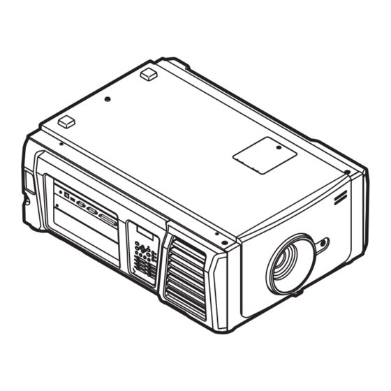
- Page 1 DLP Cinema Projector ® User’s Manual DLP Cinema Projector ® NC1000C Model No. NP-NC1000C...
-
Page 2: Important Information
Important Information Precautions: Please read this manual carefully before CAUTION using your NC1000C and keep the manual handy for future reference. • In order to reduce any interference with radio and tele- The NC1000C (projector unit) is called the “projector” , and vision reception use a signal cable with ferrite core the NP-90MS02 (integrated media server) is called the attached. - Page 3 Important Information 12. If you wish to have the projector installed on the ceiling; 3. Handle the power cable carefully. A damaged or frayed • Do not attempt to install the projector yourself. power cable can cause electric shock or fire. • The projector must be installed by qualified techni- • Do not bend or tug the power cable excessively. cians in order to ensure proper operation and reduce • Do not place the power cable under the projector, or any heavy object.
- Page 4 Important Information Cleaning 3. Due to the lamp being sealed in a pressurized environ- ment, there is a small risk of explosion, if not operated 1. Turn off the projector and unplug the power cable before correctly. There is minimal risk involved, if the unit is in cleaning the cabinet or replacing the lamp. proper working order, but if damaged or operated 2.
- Page 5 Fax Line: +49 89 99699 500 Email Address: info@nec-displays.com WEB Address: http://www.nec-display-solutions.com In North America Company Name: NEC Display Solutions of America, Inc. Address: 500 Park Boulevard, Suite 1100 Itasca, Illinois 60143, U.S.A. Telephone: +1 800 836 0655 Fax Line: +1 800 356 2415 Email Address: pjtechsupport@necdisplay.com...
-
Page 6: Table Of Contents
Table of Contents Important Information ..............2 1.What’s in the Box? and the Names of the Projector Parts ..... 7 1-1. Features ..................................7 1-2. What’s in the Box? ..............................9 1-3. Names of the Projector Parts ..........................10 2.Installation and Connection ............16 2-1. -
Page 7: What's In The Box? And The Names Of The Projector Parts
® Complies with the strict projection standards defined by the Digital Cinema Initiatives (DCI) industry group in the United States using leading imaging technology of NEC. It also supports 3D projection and high frame rates (HFR). • Reduced installation space and increased freedom through a more compact and lightweight body By employing a compact 0.69” DLP Cinema chip, the DLP Cinema projector is compact and lightweight with dimensions of 621mm (wide) ×... - Page 8 1. What’s in the Box? and the Names of the Projector Parts (2) Frequently used titles can be registered in preset buttons The projector has been equipped with 16 preset buttons that make it easy to select registered title (input signal). To this projector, 100 titles at most can be registered (input signal registration).
-
Page 9: What's In The Box
1. What’s in the Box? and the Names of the Projector Parts 1-2. What’s in the Box? Check the content of the accessories. Projector Power cable stopper Dust cap for lens Service door key x 2 Dummy bracket Important Information CD-ROM (User’s Manual) In the event that you did not receive all of the accessories outlined above, or some are damaged, contact your dealer/distributor. -
Page 10: Names Of The Projector Parts
1. What’s in the Box? and the Names of the Projector Parts 1-3. Names of the Projector Parts 1-3-1. Front of the Projector 1. STATUS indicator These indicate the status of the projector. When the projector is operating normally, these light/blink in green or orange. When an error occurs, they light/blink in red. - Page 11 1. What’s in the Box? and the Names of the Projector Parts Do not cover the air inlets and outlet while the projector is in operation. Insufficient ventilation leads to a rise of NOTE the internal temperature and may cause a fire or malfunction. 1-3-2.
- Page 12 1. What’s in the Box? and the Names of the Projector Parts Do not cover the air inlets and outlet while the projector is in operation. Insufficient ventilation leads to a rise of NOTE the internal temperature and may cause a fire or malfunction. CAUTION: DO NOT TOUCH THE LAMP immediately after it has been used.
- Page 13 1. What’s in the Box? and the Names of the Projector Parts 1-3-4. Connection terminals 1 2 3 REMOTE RS-232 GP I/O 1. Service terminal (REMOTE) (Stereo mini) This terminal is used for service purpose only. 2. Ethernet port (LAN) (RJ-45) The port for interfacing with an image signal server or controlling the projector from a PC via a network.
- Page 14 1. What’s in the Box? and the Names of the Projector Parts 1-3-5. Control panel 1. LCD screen The LCD screen displays menus and setting values for the projector operations. 2. /// (UP/DOWN/LEFT/RIGHT) buttons Press these buttons to select a menu item while a menu is displayed. 3.
- Page 15 1. What’s in the Box? and the Names of the Projector Parts 11. IMB button (planned to be supported in a future update) This button is operable when the media block is installed in the projector. Press this button to display the operation menu of the media block. 12.
-
Page 16: Installation And Connection
Installation and Connection 2-1. Steps for setting up and connecting Use the following steps for setting up your projector: • Step 1 Setup the screen and projector. (Contact your dealer to carry out the setup.) • Step 2 Connect the power cable to the projector. (See page 17) • Step 3 Connect cables to the image input terminals. -
Page 17: Connecting The Power Cable
2. Installation and Connection 2-2. Connecting the Power Cable The power cable is not included with the projector. Use a power cable that meets the standards and power supply voltage of the country where you are using the projector. Ask your dealer for the power cable to select and purchase. WARNING: Carefully read the contents described in this section before connection and connect the cables according to the proper procedure. - Page 18 2. Installation and Connection Connect the AC power supply cable. Connect the AC power supply cable to the projector. VOLTAGE SELECT switch AC input...
- Page 19 2. Installation and Connection Set VOLTAGE SELECT switch according to the voltage being used. Voltage of power to use Power cable to use Position of the VOLTAGE SELECT switch AC100V-130V outlet AC100V-130V power cable “100 130V–” AC200V-240V (single phase) outlet AC200V-240V power cable “200 240V–”...
- Page 20 2. Installation and Connection Using the supplied power cable stopper To prevent the power cable from accidently removing from the AC IN of the projector, attach the supplied power cable stopper to clamp the power cable. CAUTION: • To prevent the power cable from coming loose, make sure that all the prongs of the power cable are fully inserted into the AC IN terminal of the projector before using the power cable stopper to fix the power cable.
- Page 21 2. Installation and Connection Slide the clamper to the hilt of the power cable. This completes the attachment of the power cable stopper. Removing the power cable from the power cable stopper Push the clamper of the power cable stopper to unclasp it. knob Push the power cable clamper to open it wide enough to pull out the power cable.
-
Page 22: Connecting The Image Input Terminals
2. Installation and Connection 2-3. Connecting the image input terminals The video input ports that can be used with the IMB are as follows. Refer to the instruction manual of the IMB for details on connecting the video input ports with external equipment. NP-90MS02 HDMI input port 3G SDI input port... -
Page 23: Projection Of Images (Basic Operation)
Projection of Images (Basic Operation) 3-1. Steps of projecting images • Step 1 Turn on the power to the projector. (See page 24) • Step 2 Select the title of input signal. (See page 27) • Step 3 Adjust the position and size of the projected screen. (See page 28) • Step 4 Turn off the power to the projector. -
Page 24: Turning Your Projector On
3. Projection of Images (Basic Operation) 3-2. Turning your projector on • Connect the power cable to the projector. (See page 17) Preparation: • Supply AC power to the projector. • Turn off the main power switch to the projector when supplying or cutting AC power to the projector. NOTE Supplying or shutting down the AC power while the main power switch is on will damage the projector. • Turning on and off the projector involves a two-step operation;... - Page 25 3. Projection of Images (Basic Operation) Turn on the main power switch on the side of the projector. A buzzer will ring on the projector. The POWER button indicator will blink green and the STATUS indicator will light orange (standby state). KEY LOCK becomes automatically on if no control panel operation takes place in the standby state for 30 seconds by default.
- Page 26 3. Projection of Images (Basic Operation) Press the LAMP ON/OFF button on the control panel for three seconds or longer. The lamp is turned on and the screen glows light about 15 seconds later. The LAMP ON/OFF button indicator blinks in cycles of 2 (and changes to steady green light 90 seconds later).
-
Page 27: Selecting The Title Of Input Signal
3. Projection of Images (Basic Operation) 3-3. Selecting the title of input signal This projector allows you to select pre-registered title (input signal) using the preset buttons on the control panel (up to 16 titles). Request your dealer/distributor for details on registering and changing titles. This section explains the steps for select- ing registered titles. -
Page 28: Adjusting The Position And The Size Of Projected Screen
3. Projection of Images (Basic Operation) 3-4. Adjusting the position and the size of projected screen 3-4-1. Displaying the test pattern Press the MENU button, or select a test pattern from preset buttons (button <1> to <8>). If you register the test patterns to the preset buttons (<1> to <8> buttons), select the test pattern according to “3-3. Selecting the title of input signal (See page 27)”. - Page 29 3. Projection of Images (Basic Operation) Display on the LCD the name of the test pattern to be projected, then press the ENTER button. The test pattern is displayed. To cancel the test pattern display, select the title of the signal to project or select the “OFF” test pattern. 3-4-2.
- Page 30 3. Projection of Images (Basic Operation) 3-4-3. Adjustment of the size (zoom) and focus of the projected screen Press the MENU button. Press the LEFT/RIGHT button to display “Configuration” on the LCD screen. Press the DOWN button. Press the LEFT/RIGHT button to display “Lens Control” on the LCD screen. Press the DOWN button. The screen (“Lens Position”) to adjust the position of the projected screen is displayed.
- Page 31 3. Projection of Images (Basic Operation) 3-4-4. Adjusting the brightness of the projected screen (Lamp output) Press the LAMP button. The screen to adjust the lamp output is displayed. Press the ENTER button to switch the display between “Lamp Setup (Adjust)” and “Lamp Setup (Lamp Mode)”. Note that while the LAMP ON/OFF button indicator is blinking green (page 66), you cannot use the lamp mode settings screen because the lamp cannot be turned off and the lamp mode cannot be set.
- Page 32 3. Projection of Images (Basic Operation) 3-4-5. Adjusting the brightness of the projected screen (Lamp mode) While the LAMP ON/OFF button indicator is blinking green (page 66), you cannot use the lamp mode settings NOTE screen because the lamp mode cannot be set. Wait until the LAMP ON/OFF button indicator changes from blink- ing to steady on.
-
Page 33: Preventing Misoperations
3. Projection of Images (Basic Operation) 3-5. Preventing misoperations Buttons on the control panel can be locked (KEY LOCK) to prevent misoperations. Buttons on the control panel do not function while KEY LOCK is on. KEY LOCK must be off to operate these buttons. • KEY LOCK is automatically turned on in the following cases. -
Page 34: Turning On/Off The Lamp With The Projector Turned On
3. Projection of Images (Basic Operation) 3-6. Turning on/off the lamp with the projector turned on The indicators on the control panel blink when the following operations are carried out. (See page 65) NOTE • When you turn the lamp on or change the lamp mode The indicators of the POWER button and the LAMP ON/OFF button blink green. -
Page 35: Turning Your Projector Off
3. Projection of Images (Basic Operation) 3-7. Turning your projector off The indicators on the control panel blink when the following operations are carried out. (See page 65) NOTE • When you turn the lamp on or change the lamp mode The indicators of the POWER button and the LAMP ON/OFF button blink green. - Page 36 3. Projection of Images (Basic Operation) Turn off the AC power to the projector. In the following instances, do not turn off the main power switch or disconnect the AC power. Doing so can dam- NOTE age the projector. • While projecting images • While the fan is running after the power is turned off (The cooling-off time is 90 seconds)
-
Page 37: Using Menus
Using Menus 4-1. Basic operation with adjustment menus To adjust the projector, display the menu on the LCD screen of the projector control panel. 4-1-1. Screen display The menu display screen is composed of a menu display field (the upper two lines) and a setting item display field (the bottom two lines). - Page 38 4. Using Menus When not displaying menus, the following screen is normally displayed. When in standby When the projector is in a standby state (the main power switch in on), the following is displayed. When power is turned on When the power is turned on, the following is displayed. ←...
- Page 39 4. Using Menus 4-1-2. Operating menus Preparation: Turn your projector on. (See page 24) Press the MENU button on the control panel of your projector. The menu is displayed in the LCD screen. Press the LEFT/RIGHT buttons to display “Information.” At each press of the LEFT/RIGHT buttons, the display will cycle as “Title Select”...
- Page 40 4. Using Menus Press the DOWN button. The submenu “BIOS” another rank lower than “Model” is displayed. Press the LEFT/RIGHT button to select the submenu “Release Package.” At each press of the LEFT/RIGHT button, the display will cycle as “Model” ←→ “Serial No.” ←→ “Release Package” ←→...
- Page 41 4. Using Menus 4-1-3. How to enter alphanumeric characters Alphanumeric characters are entered for items, such as the log file of the specified period is written to USB memory. (See page Characters can be entered by pressing numeric buttons on the control panel on this projector. Move right and left Delete entered characters Enter characters...
-
Page 42: Table Of Adjustment Menus
4. Using Menus 4-2. Table of adjustment menus Menus in parentheses are menus for our service personnel. Normally, these menus cannot be used. Reference Main menu Submenu Description page Title Select “Title Memory Name” Selects the title of the signal to be projected. TEST Pattern Selects the test pattern to be projected. -
Page 43: Title Select
4. Using Menus 4-3. Title Select 4-3-1. Title select (Title Memory) Selects the title of the signal to be projected. You can register up to 100 titles. You can also assign registered titles to the preset buttons (<1> to <8> buttons) on the projec- tor’s control panel and call them up directly using those buttons. -
Page 44: Configuration
4. Using Menus 4-4. Configuration Please request your dealer/distributor to perform the settings. 4-4-1. Lamp Setup Adjust Adjusts the lamp output (brightness). ← Displays the current output power value (%) when the lamp rated output is 100%. ← Displays the current power value (W). Lamp Mode Selects the lamp to use. - Page 45 4. Using Menus 4-4-2. Lens Control Adjust the position, size, and focus of the projected screen. Press the ENTER button to switch the display between “Lens Position” and “Focus Zoom” adjustments. Press the EXIT button to return to a menu one level above. Lens Position Adjusts the position of the projected screen.
- Page 46 4. Using Menus 4-4-3. Reset This is used to reset the lamp and air filter usage times. Lamp Usage Resets the lamp usage time. When both lamp 1 and lamp 2 are replaced at the same time, reset the usage times of both lamp 1 and lamp 2.
-
Page 47: Title Setup
4. Using Menus 4-5. Title Setup Sets the title to be assigned to the preset buttons (<1> to <8> buttons) (up to 16 titles). Request your dealer/distributor to perform the settings. 4-6. Information Displays the hours of lamp use, the version information and error codes. 4-6-1. - Page 48 4. Using Menus 4-6-3. Preset Button Sets the title to be assigned to the preset buttons (<1> to <8> buttons) on the projector’s control panel. ← Selects the preset button number whose contents you want to display. ← Displays the assigned title numbers. ←...
- Page 49 4. Using Menus 4-6-6. Version Displays version information about the projector, optional boards, and IMB. System Displays the version information of the projector. ← Selects the item to display. ← Displays the version information. • Model • Serial No. • Release Package • Kernel • U-Boot • System Files...
- Page 50 4. Using Menus 4-6-8. Setup Date Displays the date when the projector was set up (starting date of the warranty period). ← Displays the date when the projector was set up (starting date of the warranty period). 4-6-9. Option Status Displays the link status of the device mounted in slot on the projector.
-
Page 51: Maintenance Of Your Projector
Maintenance of Your Projector Please request your dealer to perform cleaning of the projector inside. NOTE 5-1. Cleaning the Cabinet Before carrying out maintenance of your projector, be sure to always check that the projector is turned off and the power plug is unplugged from the electrical outlet. -
Page 52: Replacing The Lamp And The Air Filter
5. Maintenance of Your Projector 5-3. Replacing the Lamp and the Air Filter 5-3-1. Warnings About Replacing the Lamp When the usage time of the lamp being used as the light source exceeds the lamp replacement time (approximate), the mes- sage “Lamp1 OverTime”... - Page 53 5. Maintenance of Your Projector 5-3-2. Warnings About Replacing the Air Filter Air filters are attached over the air inlet of the projector to prevent dust. Replace air filters periodically to maintain the projector’s performance. WARNING: • When replacing air filters, turn off the projector and unplug the power cable. • Dust in air filters will hinder ventilation of the projector, lead to a rise of the internal temperature and can cause a fire or malfunction.
- Page 54 5. Maintenance of Your Projector 5-3-3. Procedure for Replacing the Lamp and Air Filter • Step 1 Replace the lamp (See page 54) • Step 2 Replace the rear air filter (See page 58) Replace the side air filter (See page 61) • Step 3 Reset the lamp usage time and air filter usage time (See page 63) 5-3-4.
- Page 55 5. Maintenance of Your Projector Remove the lamp housing. 1. Loosen the two screws securing the lamp housing until the Phillips screwdriver goes into a freewheeling condition. The two screws are not removable. 2. Grasp the handle and remove the lamp housing. At this time, pull the lamp housing straight out.
- Page 56 5. Maintenance of Your Projector Install a new lamp housing. 1. Insert a new lamp housing until the lamp housing is plugged into the socket. 2. Secure it in place with the two screws. Be sure to tighten the screws. Be sure to install both Lamp 1 and Lamp 2.
- Page 57 5. Maintenance of Your Projector Reattach the lamp cover. 1. Align the protrusions (2 locations) in the lamp cover with the receptacle holes in the projector and mount the lamp cover. 2. Tighten the screw to secure the lamp cover. Be sure to tighten the screw.
- Page 58 5. Maintenance of Your Projector 5-3-5. Replacing the Rear Air Filter Preparation: Replace the lamp first. (See page 54) Open the filter cover. 1. Loosen each of the two knobs by turning them counterclockwise. The knobs are not removable. If the knob is too tight to turn, use a Phillips screwdriver. 2.
- Page 59 5. Maintenance of Your Projector Remove the air filter. Pull the right side of the air filter towards you to remove it. Mount the air filter to the projector. Look for an arrow (↑AIR FLOW) indicating the installation direction on the side of the air filter. Point the arrow towards the projector.
- Page 60 5. Maintenance of Your Projector Mount the filter cover to the projector. 1. Grasp the knob on the filter cover and mount it to the projector. 2. Tighten the two knobs clockwise to secure the filter cover. This completes replacing the rear air filter. Next, replace the side air filter. Always reset the Filter1 usage time after replacing the rear air filter.
- Page 61 5. Maintenance of Your Projector 5-3-6. Replacing the Side Air Filter Preparation: Replace the lamp first. (See page 54) Remove the filter cover. The filter cover is fastened by plastic clips (4 locations). Grasp the top and bottom edges of the cover and pull it towards you to remove it.
- Page 62 5. Maintenance of Your Projector Remove the air filter. Pull the upper part of the air filter towards you and lift it up to remove it. Mount the air filter to the projector. Look for an arrow (↑AIR FLOW) indicating the installation direction on the side of the air filter. Point the arrow towards the projector.
- Page 63 5. Maintenance of Your Projector Mount the filter cover to the projector. 1. Align the positions of the plastic clips (4 locations) with the clip receptacle holes on the projector. 2. Push it in straight to fasten the filter cover. Clip receptacle holes Clip receptacle holes This completes replacing the side air filter.
-
Page 64: Appendix
Appendix 6-1. Troubleshooting Before asking for repair, please check your connection, settings and operation once again. If the trouble cannot be corrected, please contact your dealer/distributor for instructions or repair. 6-1-1. Problems and where to check Problem Check these items The projector cannot be turned on. -
Page 65: Indicator Display List
6. Appendix Problem Check these items Video image is disturbed. Check whether the signal cable connected to the projector is disconnected. The STATUS indicator blinks in red. Your projector may have trouble. Please contact your dealer/distributor for instructions. An error code is displayed. Please contact your dealer/distributor for instructions. - Page 66 6. Appendix 6-2-3. POWER button Indicator condition Projector condition Note The projector power supply is off. Blinking light Orange While the projector software is starting Wait for a moment. Green Preparing to turn power on/cooling fan rotating Wait for a moment. (cycles of 1) (State from turning the power off to entering standby (Note 1)
- Page 67 6. Appendix 6-2-6. STATUS indicator Indicator condition Projector condition Note Main power is off. Blinking light Green The projector is getting ready to turn on. Wait for a moment. The douser is closed. The lamp is off. Orange The projector is cooling down. Wait for a moment.
-
Page 68: Operation Using An Http Browser
“HOSTS” file of the computer being used. (Example 1) When the host name of the projector has been set to “pj.nec.co.jp” http://pj.nec.co.jp/index.html is specified for the address or the entry column of the URL to access HTTP server functions. - Page 69 6. Appendix 6-3-4. Structure of the HTTP server Power Controls the power to your projector. • On: Turns the power on. • Off: Turns the power off. Lamp Turn the lamp on/off. • On: Turns the lamp on. • Off: Turns the lamp off. Title List Displays titles set in the projector (such as input port, screen type, and title).
-
Page 70: Writing Of The Log File (Save Information)
6. Appendix 6-4. Writing of the log file (Save Information) Log files saved on the main unit can be written to USB memory connected to the USB port of the main unit. To perform the writing of the log file, use the following procedure. Connect the USB memory to the USB port of the main unit. - Page 71 6. Appendix When “Manual” is selected, specify the log file writing period. For how to enter numerals, refer to “4-1-3. How to enter alphanumeric characters” (See page 41). If you press the ENTER button, the display advances to the following screen. ←...
- Page 72 6. Appendix 6-4-1. Names of log files Written log files are saved with the following file names. (Model name)_(Serial Number)_YYMMDDHHmm.txt (Model name) This shows the model of projector. (Serial Number) This shows the serial number of projector. YYMMDDHHmm Shows the date/time when written. YY: Year (lower 2 digits) MM: Month (2 digits) DD: Date (2 digits)
-
Page 73: Outline Drawing
6. Appendix 6-5. Outline Drawing 476.4 (33) 460.4 Units: mm... -
Page 74: Specifications
6. Appendix 6-6. Specifications Model name NC1000C Projection method 3 chip DLP Cinema® method 0.69-inch DC2K chip Panel resolution 2048 x 1080 Lamp type 400W AC lamp Screen sizes Max. 10.6 m @14ft-L / Screen Gain 1.8 (Depends on setup conditions) Contrast ratio 1600:1 with DCI specified color representation Lens adjustment function... -
Page 75: Power Cable
6. Appendix 6-7. Power Cable Ask your dealer for the power cable to select and purchase. NOTE Power Cable Electrical Specification The projector is equipped with an IEC60320 C19 connector to connect an AC power supply cable. Ensure that the AC power cables that connect the connectors built into the projector to the AC power mains have the current capacities as shown below. - Page 76 6. Appendix Japan Plug Cable Connector JIS C 8303 VCTF 3 x 2.0mm IEC 320 C19 China Plug Cable Connector GB2099 RVV 300/500 GB17465.1 Connector Dimensions of the connector of the power cable are shown below. -0.9 -0.7 ± +0.5 + 0.5 R3.5 min +0.5...
-
Page 77: Pin Assignment And Functions Of Terminal
6. Appendix 6-8. Pin Assignment and Functions of Terminal 6-8-1. PC CONTROL connector (RS-232) (D-Sub 9 pin) This is an RS-232C interface for controlling the projector from a PC. The projector operates as a DCE (Data Communication Equipment), so use a straight cable when connecting to a PC. Pin No. - Page 78 6. Appendix 6-8-2. External control connector (GP I/O) (D-Sub 37 pin) It is possible to control the projector with an external device and to control the external device from the projector using an external control connector (GPIO: General Purpose I/O Ports). Each pin is electrically separated from the projector internal circuits by a photo-coupler.
- Page 79 6. Appendix Input Connector GP I/O Connector Inside Projector Resist = 390 Ω Ext_GPIN_P Pin No.: Voltage applied across the pins of Ext_GPIN_P and Ext_GPIN_N should be in the range from 3.3 Vdc to 10 Vdc. Recommended Operating Current: 5mA Absolute Maximum Rating: 23mA Ext_GPIN_N...
- Page 80 6. Appendix • Timing chart of GPIO control Example of Select Preset Button Off at least 500 ms at least 500 ms approx. 200 ms 8-27 5-24/6-25/7-26 time Execute Select Preset Button Example for turning the image douser (Douser) on Off at least 500 ms at least 500 ms approx.
- Page 81 6. Appendix Example of Lamp On Off at least 500 ms at least 500 ms approx. 200 ms 5-24/6-25 7-26/8-27 time Execute Lamp On Example for turning the power off Off at least 500 ms at least 500 ms approx. 200 ms 6-25 5-24/7-26/8-27 time...
- Page 82 6. Appendix Output Connector GP I/O Connector Inside Projector Ext_GPOUT_P Ext_PROJ_GOOD_P Pin No.: 9 10 11 12 13 14 15 16 Absolute Maximum Rating: 50 mA Ext_GPOUT_N Ext_PROJ_GOOD_N Pin No.: 28 29 30 31 32 33 34 35 Photo-coupler • Using GPIO Control You can use GPIO control for the projector’s health check and error check.
- Page 83 6. Appendix 6-8-3. 3D connector (D-sub 15 pin) This is used to connect a 3D image system to the projector. Pin view of a female connector Pin No. Signal Name Function +12V Supplies power (+12V) to the 3D image system GNDC Ground GNDC...
-
Page 84: Related Products List
6. Appendix 6-9. Related products list Product name Lens memory Model name Lens Zoom lens 1.63 to 2.03 NP-9LS16Z1 Zoom lens 2.03 to 2.72 NP-9LS20Z1 Zoom lens 4.07 to 6.34 NP-9LS40Z Zoom lens 1.2 to 1.72 ○ NP-9LS12ZM1 Zoom lens 1.33 to 2.1 NP-9LS13ZM1 ○... - Page 85 © NEC Display Solutions, Ltd. 2016 Ver.1 6/16...