
Related Manuals for Dell PowerVault MD2412


Summary of Contents for Dell PowerVault MD2412
- Page 1 Dell PowerVault MD2412 and MD2424 Direct-Attach Storage for PowerEdge Servers Owner's Manual Regulatory Model: QUIAE/CONAE May 2023 Rev. A00...
- Page 2 A WARNING indicates a potential for property damage, personal injury, or death. © 2023 Dell Inc. or its subsidiaries. All rights reserved. Dell Technologies, Dell, and other trademarks are trademarks of Dell Inc. or its subsidiaries. Other trademarks may be trademarks of their respective owners.
-
Page 3: Table Of Contents
Contents Chapter 1: System overview......................5 Locate the service tag............................... 5 MD2412 and MD2424 front view.............................5 MD2412 and MD2424 back view............................. 6 MD2412 and MD2424 LEDs.............................. 6 Front panel LEDs................................6 2U enclosure drive carrier module LEDs........................8 EMM LEDs..................................8 PSU LEDs.................................. - Page 4 Chapter 7: Getting help....................... 32 Contacting Dell...................................32 Accessing system information using the QRL......................32 Appendix A: Technical specifications..................33 Appendix B: Standards and regulations..................36 Potential for radio frequency interference......................... 36 ICES-003 (Canada)................................36 Recycling of Waste Electrical and Electronic Equipment (WEEE)................36...
-
Page 5: Chapter 1: System Overview
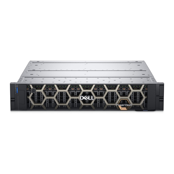
System overview The MD2412 and MD2424 enclosures provide direct-attach storage to servers. They connect directly to the SAS ports on the back of a host system, and the management software running on the host system manages the enclosure. The MD2412 2U enclosure supports up to 12 3.5‐inch drives installed in a four‐column, three-row configuration. The MD2424 2U enclosure supports up to 24 2.5‐inch drives installed vertically side by side. -
Page 6: Md2412 And Md2424 Back View
3. Service tag MD2412 and MD2424 back view The MD24 Series systems contain two hot-swappable EMMs and two hot-swappable PSUs. NOTE: The EMMs are not interchangeable between MD2412 and MD2424 systems. Figure 2. MD2412 and MD2424 back view (AC PSU) 1. - Page 7 Index Indicator Description Color Status Temperature fault Amber ● Off: Normal operation ● On: Thermal fault such as temperature, fan, and heatsink fault Electrical fault Amber ● Off: Normal operation ● On: Electrical fault related to voltage or System overview...
-
Page 8: 2U Enclosure Drive Carrier Module Leds
2U enclosure drive carrier module LEDs Two LEDs mounted on the front of each drive carrier module provide drive status. The drive module LEDs are identified in the figure, and the LED behavior is described in the table following the figure. Figure 4. -
Page 9: Psu Leds
Index Indicator Description Color Status EMM ID Blue ● Off: Normal operation ● Blinking (1 sec. on, 1 sec. off): Identify EMM status Green On solid: Normal operation Amber Blinking (2 sec. on, 1 sec. off): Fault Not used Mini SAS status Green ●... -
Page 10: Chapter 2: Safety Precautions
Always follow these safety precautions to avoid injury and damage to the PowerVault MD equipment. If equipment described in this guide is used in a manner that is not specified by Dell , the protection provided by the equipment could be impaired. -
Page 11: Moving Fan Blade Precaution
Moving fan blade precaution A warning symbol as shown below (or similar) that is combined with the triangle shaped warning sign from ISO 3864-2 indicates a moving part. CAUTION: Keep fingers and other body parts away from the moving blade. Failure to take this precaution may result in personal injury. -
Page 12: Chapter 3: Installing The Enclosure In The Rack
Installing the enclosure in the rack The rack mounting rails provided with the enclosure fit in 19-inch rack cabinets. The rails have been designed and tested for the maximum enclosure weight and rack capacity. Use of other mounting hardware may cause some loss of rack space. Installing rails onto the rack First install the rails that were shipped with the unit onto your rack. -
Page 13: Install The Enclosure Into The Rack
Figure 9. Securing the rails to the rack 7. Repeat these steps for the second rail. Install the enclosure into the rack Steps 1. Use two people to lift the enclosure and align it with the installed rails. NOTE: Ensure that the enclosure remains level while inserting it in the rack. 2. -
Page 14: Attach The Bezel
Figure 11. Securing the enclosure to the rack Attach the bezel The enclosure includes an optional bezel that you can attach to the front of the enclosure. Steps 1. Hook the right side of the bezel onto the right ear cover of the chassis. 2. -
Page 15: Chapter 4: Connecting Sas And Power Cables
Connecting SAS and power cables Connect SAS cables to the host system and then connect the power cables to the enclosure. Connect SAS cables You can cable the storage enclosure using either a four-port HBA or a two-port PERC: ● A four-port SAS HBA supports up to eight MD2412 enclosures or four MD2424 enclosures. ●... -
Page 16: Connect Power Cables
Figure 14. Example of SAS4 cabling using a two-port PERC adapter Connect power cables Connect power cables to the enclosure after you connect the SAS cables to the host system. Steps 1. Plug each power cable into a power supply unit (PSU). If the power cable is connected to the facility power, the power supply starts up immediately when the power cable is connected to the chassis. -
Page 17: Verify Connections
1. To use iDRAC, go to the Storage>Enclosures view and verify that the enclosure is listed. See the Integrated Dell Remote Access Controller User's Guide for details about using iDRAC. 2. To use PowerTools SHM CLI, run the following command: shmcli list enclosures See the PowerTools Server Hardware Manager Administrator's Guide for details about using these commands. -
Page 18: Chapter 5: Troubleshooting
Dell technical support. Damage due to servicing not authorized by Dell is not covered by your warranty. Read and follow all the safety instructions before troubleshooting your system or replacing any parts. -
Page 19: Troubleshooting Drives
4. Reinstall the EMM and wait for 30 seconds. 5. Turn on the enclosure. 6. Check the status LED. 7. If the problem is not resolved, swap or replace the EMM with a known good EMM. 8. If the problem persists, see Getting help. -
Page 20: Chapter 6: Replacing Components
If you do not have any of the suggested equipment for proper grounding, have an authorized technician install the part. For more information about static electricity or assistance with product installation, contact customer support. For additional information, see www.dell.com/support. Replacing components... -
Page 21: Updating Firmware
You can use either the Dell Update Package or PowerTools SHM CLI for firmware updates. ● Dell Update Package: Can be used to update both drive and EMM firmware. See the Dell Update Packages User's Guide for information about how to update firmware. -
Page 22: Sas Drives
SAS Drives To replace a drive, remove the drive carrier from the expansion enclosure and replace the drive in the carrier. Drives are hot-swappable, which means they can be replaced without powering off the enclosure. Failed disk drives must be replaced with approved disk drives. - Page 23 Figure 18. Installing a drive blank Removing the drive carrier Remove the drive carrier from the enclosure to replace the drive. Prerequisites Use the system manager software to prepare the drive for removal. If the drive is online, the green activity or fault indicator blinks while the drive is powering off.
- Page 24 Figure 20. Removing the drive from the drive carrier Installing a drive into a drive carrier Steps 1. Insert the drive into the drive carrier with the connector end of the drive at the back. 2. Align the screw holes on the drive with the back set of holes on the drive carrier. When aligned correctly, the back of the drive is flush with the back of the drive carrier.
- Page 25 Figure 21. Installing a drive carrier 3. Ensure that the drive fault indicator turns off, and use your system manager software to verify that the drive is operating properly. Replacing components...
-
Page 26: Power Supply Unit
Power supply unit You may need to replace a power supply unit (PSU) if your system manager or the PSU LED shows a failure. The PSU is hot-swappable—you can replace a PSU without turning off the enclosure. 1. Follow the safety guidelines listed in the Safety instructions. 2. -
Page 27: Emm
Figure 23. Installing the PSU 2. Push the PSU into the chassis. 3. Ensure that the latch clicks into place, which engages the PSU into the chassis connectors. 4. Rotate the handle to the vertical position. 5. Connect the power cable to the PSU. The power supply turns on immediately when the cable is connected. - Page 28 Figure 25. Removing the EMM 2. Rotate the handle to release the EMM from the chassis. 3. Hold the handle and guide the EMM out of the chassis. Installing the EMM Steps 1. Rotate the release latch on the EMM 45°. Figure 26.
- Page 29 Removing the EMM cover You need to remove the EMM to replace a failed fan. Steps 1. Remove the EMM from the enclosure. See Removing the EMM. 2. Press the lock on the top of the EMM and slide the cover toward the back of the unit. Figure 27.
-
Page 30: Fans
Fans Each EMM contains three fans. The temperature icon on the front of the enclosure turns amber to indicate a fan failure, and your system manager shows more details about the failed fan. You need to remove the EMM to access the fans. 1. - Page 31 Figure 30. Installing a fan 3. Install the EMM cover. See Installing the EMM cover. 4. Install the EMM into the enclosure. See Installing the EMM. 5. Ensure that the temperature indicator on the front of the chassis is turned off, and use your system manager software to verify that the fan is operating properly.
-
Page 32: Chapter 7: Getting Help
About this task Dell provides several online and telephone-based support and service options. Availability varies by country and product, and some services may not be available in your area. To contact Dell for sales, technical support, or customer service issues: Steps 1. -
Page 33: Appendix A: Technical Specifications
Technical specifications This section describes the technical specifications of the MD2412 and the MD2424 enclosures. Enclosure dimensions Table 1. Enclosure dimensions Specification MD2412 MD2424 Height 86.8 mm (3.4 in.) 86.8 mm (3.4 in.) Width 444 mm (17.5 in.) 444 mm (17.5 in.) Depth 545 mm (21.5 in.) 497 mm (19.5 in.) - Page 34 Table 4. Other environmental requirements Specification Measurement or description Altitude, operating 900 meters @ 45°C ; 3050 meters @ 33°C NOTE: Ramp Altitude at 3.81m/s and temperature at 20˚C/Hr Altitude, non-operating Maximum 12,000 m (39,370 ft) Shock, operating 6.0 g, 11 ms. Four shocks positive and four negative in each of 3 axes, 24 total shocks.
- Page 35 Table 5. AC Power supply unit specifications (continued) Specification Measurement ● > 0.99 @ 100% load iTHD Maximum iTHD% ● <20% @ 5%-10% load ● <15% @ >10% load ● ≤10% @ ≥20% load ● ≤8% @ ≥40% load ● ≤5% @ ≥50% load Technical specifications...
-
Page 36: Appendix B: Standards And Regulations
Any modifications made to this device that are not approved by Dell may void the authority that is granted to the user by the FCC to operate this equipment.