Table of Contents
Advertisement
Quick Links
Cisco Wide Area Virtualization Engine 7541, 7571,
and 8541 Hardware Installation Guide
October 3, 2016
Cisco Systems, Inc.
www.cisco.com
Cisco has more than 200 offices worldwide.
Addresses, phone numbers, and fax numbers
are listed on the Cisco website at
www.cisco.com/go/offices.
Text Part Number:
Advertisement
Table of Contents
Troubleshooting

Related Manuals for Cisco 7541


Summary of Contents for Cisco 7541
- Page 1 Cisco Wide Area Virtualization Engine 7541, 7571, and 8541 Hardware Installation Guide October 3, 2016 Cisco Systems, Inc. www.cisco.com Cisco has more than 200 offices worldwide. Addresses, phone numbers, and fax numbers are listed on the Cisco website at www.cisco.com/go/offices.
- Page 2 OR ITS SUPPLIERS HAVE BEEN ADVISED OF THE POSSIBILITY OF SUCH DAMAGES. Cisco and the Cisco logo are trademarks or registered trademarks of Cisco and/or its affiliates in the U.S. and other countries. To view a list of Cisco trademarks, go to this URL: www.cisco.com/go/trademarks.
-
Page 3: Table Of Contents
Audience Organization Conventions Related Documentation Obtaining Documentation and Submitting a Service Request Introducing the Cisco Wide Area Virtualization Engine 7541, 7571, and 8541 C H A P T E R Supported Products Hardware Features Front Panel Components and LEDs Back Panel Components and LEDs... - Page 4 Checking Connections and Switches Troubleshooting the Ethernet Controller Network Connection Problems Ethernet Controller Troubleshooting Chart Undetermined Problems Problem-Solving Tips Error Symptoms Appliance Specifications Interface Module Specifications Maintaining Your Site Environment Cisco Wide Area Virtualization Engine 594 and 694 Hardware Installation Guide...
- Page 5 Dust and Particles Corrosion Electrostatic Discharge Electromagnetic and Radio Frequency Interference Magnetism Shock and Vibration Power Source Interruptions Using Power Protection Devices Surge Protectors Line Conditioners Uninterruptible Power Supplies Cisco Wide Area Virtualization Engine 594 and 694 Hardware Installation Guide...
- Page 6 Contents Cisco Wide Area Virtualization Engine 594 and 694 Hardware Installation Guide...
-
Page 7: Preface
Preface This preface describes the purpose of the Cisco Wide Area Virtualization Engine 7541, 7571, and 8541 Hardware Installation Guide, who should read it, how it is organized, and its document conventions. This preface contains the following sections: • Purpose •... -
Page 8: Organization
Optional alternative keywords are grouped in brackets and separated by vertical bars. string A nonquoted set of characters. Do not use quotation marks around the string, or the string will include the quotation marks. Cisco Wide Area Virtualization Engine 7541, 7571, and 8541 Hardware Installation Guide... - Page 9 Means reader take note. Notes contain helpful suggestions or references to materials not contained in this manual. Caution Means reader be careful. You are capable of doing something that might result in equipment damage or loss of data. Cisco Wide Area Virtualization Engine 7541, 7571, and 8541 Hardware Installation Guide...
- Page 10 Use the statement number provided at the end of each warning to locate its translation in the translated safety warnings that accompanied this device. Statement 1071 SAVE THESE INSTRUCTIONS Cisco Wide Area Virtualization Engine 7541, 7571, and 8541 Hardware Installation Guide viii...
- Page 11 Cisco Wide Area Virtualization Engine 7541, 7571, and 8541 Hardware Installation Guide...
- Page 12 Cisco Wide Area Virtualization Engine 7541, 7571, and 8541 Hardware Installation Guide...
-
Page 13: Related Documentation
Related Documentation The WAVE-7541, WAVE-7571, and WAVE-8541 appliance supports the Cisco Wide Area Application Services software (WAAS) and can function as either a WAAS Central Manager or as an Application Acceleration Engine. The Cisco WAAS software document set includes the following documents: •... -
Page 14: Obtaining Documentation And Submitting A Service Request
Obtaining Documentation and Submitting a Service Request For information on obtaining documentation, submitting a service request, and gathering additional information, see the monthly What’s New in Cisco Product Documentation, which also lists all new and revised Cisco technical documentation, at: http://www.cisco.com/en/US/docs/general/whatsnew/whatsnew.html... -
Page 15: Introducing The Cisco Wide Area Virtualization Engine 7541, 7571, And 8541
Introducing the Cisco Wide Area Virtualization Engine 7541, 7571, and 8541 This chapter provides a basic functional overview of the Cisco Wide Area Virtualization Engine 7541, 7571, and 8541 (WAVE-7541, WAVE-7571, and WAVE-8541) appliance and describes the hardware, major components, and front and back panel indicators and controls. -
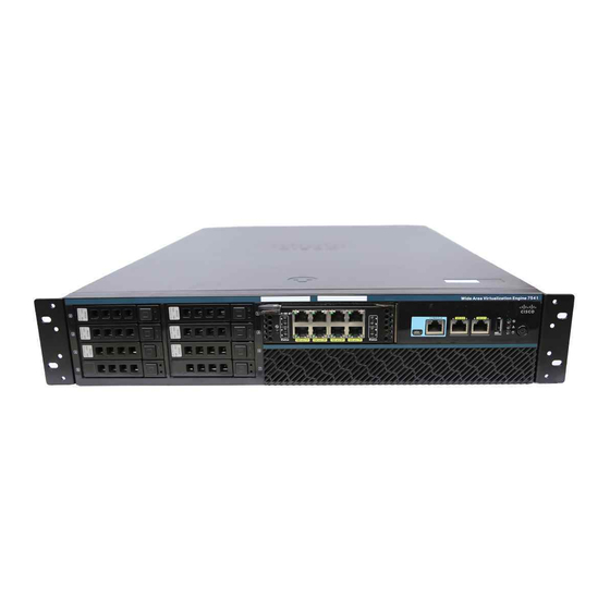
Page 16: Front Panel Components And Leds
Console port (RJ-45) Power On button Figure 1-2 shows the front panel LEDs. Figure 1-2 Front Panel LEDs Table 1-1 describes the front panel LEDs and their functions. Cisco Wide Area Virtualization Engine 7541, 7571, and 8541 Hardware Installation Guide... -
Page 17: Back Panel Components And Leds
Drive failure has occurred. Back Panel Components and LEDs Figure 1-3 shows the back panel components. Note To monitor the boot process in normal operation, use the console port. Cisco Wide Area Virtualization Engine 7541, 7571, and 8541 Hardware Installation Guide... - Page 18 Small: 4 - 9 (right to left, bottom row first) Figure 1-4 shows the back panel LEDs. Figure 1-4 Back Panel LEDs Table 1-2 describes the back panel LEDs and their functions. Cisco Wide Area Virtualization Engine 7541, 7571, and 8541 Hardware Installation Guide...
-
Page 19: Location Of Ports And Connectors
Connect a Category 3, 4, or 5 unshielded twisted-pair cable to an Ethernet connector. 100BASE-TX and 1000BASE-T Fast Ethernet standards require Category 5 or higher cabling. The WAVE-7541, WAVE-7571, and WAVE-8541 appliance has two Ethernet connectors that are attached to the Ethernet controllers (see... -
Page 20: Console Port Connectors
Ethernet Port Connector Speed LED Link/Activity Console Port Connectors The WAVE-7541, WAVE-7571, and WAVE-8541 appliance has two console port connectors, serial and mini-USB (see Figure 1-1). Use a console port connector to access the command-line interface (CLI) for controlling the WAVE appliance. -
Page 21: Installing The Cisco Usb Driver
Do not connect the cable from the Windows PC to the WAVE appliance until after the driver is installed. Step 1 Load the DVD that came with your WAVE appliance and double-click the CUSBInst.exe file. The Cisco Virtual Com InstallShield Wizard begins. - Page 22 If you happen to install the driver multiple times, each time the driver is installed the virtual COM port number assigned to the USB port gets incremented. This is expected behavior and may not get reset even if you uninstall the driver. Cisco Wide Area Virtualization Engine 7541, 7571, and 8541 Hardware Installation Guide...
-
Page 23: Preparing To Install The Wave-7541, Wave-7571, And Wave-8541
This chapter contains important safety information that you should know before you work with the WAVE-7541, WAVE-7571, and WAVE-8541. Use the guidelines in this chapter to ensure your own personal safety and to help protect your appliance from potential damage. -
Page 24: Safety Guidelines
To reduce the risk of bodily injury, electrical shock, fire, and damage to the equipment, observe the precautions in this section. This section contains the following topics: • General Precautions • System Reliability Considerations • Protecting Against Electrostatic Discharge Cisco Wide Area Virtualization Engine 7541, 7571, and 8541 Hardware Installation Guide... - Page 25 WAVE-8541: • Observe and follow service markings. Do not service any Cisco product except as explained in your system documentation. Opening or removing covers that are marked with the triangular symbol with a lightning bolt may expose you to electrical shock. Components inside these compartments should be serviced only by a trained and qualified service technician.
-
Page 26: Protecting Against Electrostatic Discharge
Each of the drive bays has either a drive or a filler panel installed. • The Interface Module bay has either a Cisco Interface Module or a filler panel installed. • For rack configurations, make sure that space is available around the appliance to enable the cooling system to work properly. -
Page 27: Understanding The Power Requirements
NEMA locking-style plugs or those complying with IEC 60309 are considered suitable for this purpose. Using common power outlet strips for the WAVE appliance is not recommended. Cisco Wide Area Virtualization Engine 7541, 7571, and 8541 Hardware Installation Guide... - Page 28 Chapter 2 Preparing to Install the WAVE-7541, WAVE-7571, and WAVE-8541 Understanding the Grounding Requirements Cisco Wide Area Virtualization Engine 7541, 7571, and 8541 Hardware Installation Guide...
-
Page 29: Installing The Wave-7541, Wave-7571, And Wave-8541
Leave a minimum clearance of 121.9 cm (48 in) from the back of the rack to the back of another rack or row of racks. The WAVE-7541, WAVE-7571, and WAVE-8541 appliances draw in cool air through the front rack door and expel warm air through the rear rack door. Therefore, the front and rear rack doors must be adequately ventilated to allow ambient room air to enter the cabinet, and the rear door must be adequately ventilated to allow the warm air to escape from the cabinet. - Page 30 Side—The clearance between the installed rack component and the side panels of the rack must be a minimum of 7 cm (2.75 in). Note Rack-mounting the WAVE-7541, WAVE-7571, and WAVE-8541 appliance is supported for rear mount in a 4-post rack only. Table 3-1 lists the rack mounting hardware included in your shipping container.
-
Page 31: Rack Mounting And Cabling The Wave-7541, Wave-7571, And Wave-8541
Rack Mounting and Cabling the WAVE-7541, WAVE-7571, and WAVE-8541 Rack Mounting and Cabling the WAVE-7541, WAVE-7571, and WAVE-8541 Note Rack-mounting the WAVE-7541, WAVE-7571, and WAVE-8541 appliance is supported in a 4-post rack only. To prevent bodily injury when mounting or servicing this unit in a rack, you Warning must take special precautions to ensure that the system remains stable. -
Page 32: Figure
Secure the chassis using four (two on each side) rack screws (item #6 or #7 in Table 3-1) through the holes in the front brackets and into the threaded holes in the mounting post. Cisco Wide Area Virtualization Engine 7541, 7571, and 8541 Hardware Installation Guide... - Page 33 Warning To reduce the risk of electric shock, fire, or damage to the equipment, do not plug telephone or telecommunications connectors into RJ-45 connectors. Figure 3-4 Cable Connections—Front Cisco Wide Area Virtualization Engine 7541, 7571, and 8541 Hardware Installation Guide...
-
Page 34: Connecting Power And Booting The System
While the WAVE appliance is powering up, the green power-on LED on the front of the appliance is on. Checking the LEDs When the WAVE-7541, WAVE-7571, and WAVE-8541 is up and running, observe the front panel LEDs (see Figure 1-1 Table 1-1) to verify that your system is operating properly. - Page 35 To replace a WAVE appliance, remove it from the network, and then install a new WAVE appliance and configure it using the same configuration parameters (IP address and so forth) that you used for the removed WAVE appliance. Cisco Wide Area Virtualization Engine 7541, 7571, and 8541 Hardware Installation Guide...
- Page 36 Chapter 3 Installing the WAVE-7541, WAVE-7571, and WAVE-8541 Removing or Replacing a WAVE Appliance Cisco Wide Area Virtualization Engine 7541, 7571, and 8541 Hardware Installation Guide...
-
Page 37: Installing Hardware Options For The Wave-7541, Wave-7571, And Wave-8541
Replacing a Fan • Replacing a Power Supply Installing a Cisco WAVE Interface Module In addition to the two onboard Gigabit Ethernet ports, the WAVE-7541, WAVE-7571, and WAVE-8541 can accommodate one optional Interface Module: • 4-port Gigabit Ethernet Copper Bypass Interface Module •... -
Page 38: Replacing A Hard Disk Drive/Solid State Drive
Interface Module—Removal Step 4 Power on the appliance. Step 5 For information about connecting cables to the Cisco WAVE Interface Module ports, see Chapter 5, “WAVE Interface Modules.” Replacing a Hard Disk Drive/Solid State Drive The WAVE appliance supports as many as eight 2.5-inch (Small Form Factor) SAS hard drives. - Page 39 Make sure that the drive is properly seated in the bay. Step 5 Close the drive handle. Cisco Wide Area Virtualization Engine 7541, 7571, and 8541 Hardware Installation Guide...
-
Page 40: Replacing A Fan
Chapter 2, “Preparing to Install the WAVE-7541, WAVE-7571, and WAVE-8541.” Step 2 Disengage the fan latch and pull the fan out by the handle (see Figure 4-2). Cisco Wide Area Virtualization Engine 7541, 7571, and 8541 Hardware Installation Guide... -
Page 41: Replacing A Power Supply
2, “Preparing to Install the WAVE-7541, WAVE-7571, and WAVE-8541.” Step 2 Remove the power cord from the power supply. Note Power supply assemblies support load-sharing. If one loses power, the second power supply takes over. Cisco Wide Area Virtualization Engine 7541, 7571, and 8541 Hardware Installation Guide... - Page 42 If a power supply alarm occurs and you power down the WAVE appliance to replace the power supply, you must use the clear bmc event-log global configuration command and then reboot to clear the alarm. Cisco Wide Area Virtualization Engine 7541, 7571, and 8541 Hardware Installation Guide...
-
Page 43: Wave Interface Modules
Network Adapter Cabling Requirements • Installation Scenarios and Cabling Examples for Fast Ethernet Connections For information on installing an inline adapter in your WAVE-7541, WAVE-7571, and WAVE-8541, see Installing a Cisco WAVE Interface Module in Chapter 4, “Installing Hardware Options for the WAVE-7541, WAVE-7571, and WAVE-8541.”... -
Page 44: Gigabit Ethernet Interface Module-Fiber Optic
Gigabit Ethernet Interface Module—8-Port Copper Gigabit Ethernet Interface Module—Fiber Optic The fiber optic Gigabit Ethernet Interface Module is available in 4 ports. This model supports bypass. (See Figure 5-3.) Cisco Wide Area Virtualization Engine 7541, 7571, and 8541 Hardware Installation Guide... -
Page 45: 10 Gigabit Ethernet Interface Module-Fiber Optic Sfp
The fiber optic Gigabit Ethernet Interface Module is available in 2 ports. This model does not support bypass. (See Figure 5-4.) Figure 5-4 Gigabit Ethernet Interface Module—2-Port Fiber Optic Cisco Wide Area Virtualization Engine 7541, 7571, and 8541 Hardware Installation Guide... -
Page 46: Inline Interface
WAVE appliance without being processed. For more information about configuring the inline network adapter, see the Cisco Wide Area Application Services Configuration Guide. -
Page 47: Ports And Led Indicators
Indicates the inline port pair is in bypass mode. — No activity exists. Figure 5-7 shows the Gigabit Ethernet ports and LEDs for the 4-port and 8-port Copper Interface Module. Cisco Wide Area Virtualization Engine 7541, 7571, and 8541 Hardware Installation Guide... - Page 48 LED Name Color State Description Interface Module Green Interface Module is receiving power. power LED — Interface Module is not installed or a power supply failure has occurred. Cisco Wide Area Virtualization Engine 7541, 7571, and 8541 Hardware Installation Guide...
- Page 49 Interface Module is not installed or a power supply failure has occurred. Activity — No link is detected. Green Link is detected. Green Blinking Transmitting. Yellow Interface Module is administratively shut down. Cisco Wide Area Virtualization Engine 7541, 7571, and 8541 Hardware Installation Guide...
-
Page 50: Network Adapter Cabling Requirements
Crossover or straight-through Crossover or straight-through WAVE to Switch Router to WAVE and Crossover or straight-through Crossover or straight-through WAVE to Router WAVE to WAVE Crossover or straight-through Cisco Wide Area Virtualization Engine 7541, 7571, and 8541 Hardware Installation Guide... - Page 51 Switch to WAVE and Straight-through Crossover WAVE to Router Switch to WAVE and Straight-through Straight-through WAVE to Switch Router to WAVE and Straight-through WAVE to Router Straight-through WAVE to WAVE Crossover Cisco Wide Area Virtualization Engine 7541, 7571, and 8541 Hardware Installation Guide...
-
Page 52: Gigabit Ethernet-Fiber Optic
The inline network adapter has four ports that are divided into two inline groups (see Ports and LED Indicators). The WAVE appliance can be physically placed inline between two distinct network paths, creating redundant WAN links. (See Figure 5-10.) Cisco Wide Area Virtualization Engine 7541, 7571, and 8541 Hardware Installation Guide 5-10... - Page 53 Fast Ethernet: WAN0 (InlinePort 1/0/wan) Cable type: Straight-through Cable type: Crossover Connection: WAVE to WAN router B (using InlineGroup 1/1) Fast Ethernet: WAN1 (InlinePort 1/1/wan) Cable type: Crossover Cisco Wide Area Virtualization Engine 7541, 7571, and 8541 Hardware Installation Guide 5-11...
- Page 54 Connection: WAVE 2 to WAN router Fast Ethernet: WAVE 2 WAN0 (InlinePort 1/0/wan) Cable type: Crossover Figure 5-12 Cabling Between Two Inline WAVEs WAVE2 inline adap Router WAVE1 inline adapter LAN switch Cisco Wide Area Virtualization Engine 7541, 7571, and 8541 Hardware Installation Guide 5-12...
- Page 55 (InlinePort 1/0/wan) to WAVE 2 LAN0 (InlinePort 1/0/lan) Cable type: Straight-through Cable type: Crossover Connection: WAVE 2 to WAN router Fast Ethernet: WAVE 2 WAN0 (InlinePort 1/0/wan) Cable type: Crossover Cisco Wide Area Virtualization Engine 7541, 7571, and 8541 Hardware Installation Guide 5-13...
- Page 56 Chapter 5 WAVE Interface Modules Installation Scenarios and Cabling Examples for Fast Ethernet Connections Cisco Wide Area Virtualization Engine 7541, 7571, and 8541 Hardware Installation Guide 5-14...
-
Page 57: Troubleshooting The System Hardware
Check the system fault LED (see System fault LED in Chapter 1, “Introducing the Cisco Wide Area Virtualization Engine 7541, 7571, and 8541). If the status is yellow, check for alarms using the show alarms command. Step 3 Power down the appliance and all external devices. -
Page 58: Checking Connections And Switches
Obtaining Documentation and Submitting a Service Request in the Preface.) Troubleshooting the Ethernet Controller This section provides troubleshooting information for problems that might occur with the 10/100/1000-Mbps Ethernet controller. Cisco Wide Area Virtualization Engine 7541, 7571, and 8541 Hardware Installation Guide... -
Page 59: Network Connection Problems
Ethernet network. If the Ethernet activity LED is off, make sure that the switch and network are operating and that the correct device drivers are installed. Ethernet Controller Troubleshooting Chart Table 6-1 lists solutions to 10/100/1000-Mbps Ethernet controller problems. Cisco Wide Area Virtualization Engine 7541, 7571, and 8541 Hardware Installation Guide... -
Page 60: Undetermined Problems
Use the information in this section if the diagnostic tests did not identify the failure, the devices list is incorrect, or the system is inoperative. Note Damaged data in CMOS can cause undetermined problems. Note Damaged data in BIOS code can cause undetermined problems. Cisco Wide Area Virtualization Engine 7541, 7571, and 8541 Hardware Installation Guide... -
Page 61: Problem-Solving Tips
Check the system LEDs for the power supplies (see Back Panel Components and LEDs in Chapter 1, “Introducing the Cisco Wide Area Virtualization Engine 7541, 7571, and 8541”). If the LEDs indicate the power supplies are working correctly, follow these steps: Step 1 Power down the appliance. -
Page 62: Error Symptoms
Table 6-3 General Problems Symptom Cause and Action Problems such as broken cover Broken component. Call your customer service representative. latch or indicator LEDs not working. Cisco Wide Area Virtualization Engine 7541, 7571, and 8541 Hardware Installation Guide... - Page 63 Verify that all of the hardware options and cable connections are work does not work now. secure. Check for a failing hardware option and replace it if necessary. Cisco Wide Area Virtualization Engine 7541, 7571, and 8541 Hardware Installation Guide...
- Page 64 (see Console Port Connectors in Chapter 1, “Introducing Cisco Wide Area the Cisco Wide Area Virtualization Engine 7541, 7571, and Virtualization Engine 7541, 8541”). 7571, and 8541.” Cisco Wide Area Virtualization Engine 7541, 7571, and 8541 Hardware Installation Guide...
-
Page 65: Appliance Specifications
This appendix contains the following sections: • Appliance Specifications • Interface Module Specifications Appliance Specifications Table A-1 provides a summary of the features and specifications of the WAVE-7541, WAVE-7571, and WAVE-8541. Table A-1 WAVE-7541, WAVE-7571, and WAVE-8541 Features and Specifications Specification Description •... - Page 66 If operating location is above 1,000 meters (3,281 feet), deduct 3 ºC (5.4 ºF) from the maximum operating temperature for each additional 1,000 meters (3,281 ft). Cisco Wide Area Virtualization Engine 7541, 7571, and 8541 Hardware Installation Guide...
-
Page 67: Interface Module Specifications
38 mm (1.5 in) H x 121 mm (4.75 in) W x 264 mm (10.38 in) D Weight 0.73 kg to 0.91 kg (1.61 lb to 2.01 lb) Cisco Wide Area Virtualization Engine 7541, 7571, and 8541 Hardware Installation Guide... - Page 68 Operating altitude 3,050 m (10,000 ft) Non-operating temperature -30 to 60 ºC (-22 to 140 ºC) Non-operating humidity 5 to 95% RH (non-condensing) Non-operating altitude 4,572 m (15,000 ft) Cisco Wide Area Virtualization Engine 7541, 7571, and 8541 Hardware Installation Guide...
-
Page 69: Maintaining Your Site Environment
WAVE-8541 in good operating condition and minimize the need for costly, time-consuming service procedures. This chapter contains maintenance procedures that you should perform regularly. This appendix covers the tasks required for maintaining a WAVE-7541, WAVE-7571, and WAVE-8541 or a WAVE-7541, WAVE-7571, and WAVE-8541 farm. -
Page 70: Temperature
However, if a system is located in an unusually humid location, a dehumidifier can be used to maintain the humidity within an acceptable range. Cisco Wide Area Virtualization Engine 7541, 7571, and 8541 Hardware Installation Guide... -
Page 71: Altitude
• Keep components in their antistatic packaging until they are installed. • Avoid wearing clothing made of wool or synthetic materials. Cisco Wide Area Virtualization Engine 7541, 7571, and 8541 Hardware Installation Guide... -
Page 72: Electromagnetic And Radio Frequency Interference
Systems can be subject to significant vibration when being transported by a vehicle or when operated in an environment with machinery that causes vibration. Cisco Wide Area Virtualization Engine 7541, 7571, and 8541 Hardware Installation Guide... -
Page 73: Power Source Interruptions
Surge protectors, however, do not offer protection against brownouts, which occur when the voltage drops more than 20 percent below the normal AC line voltage level. Cisco Wide Area Virtualization Engine 7541, 7571, and 8541 Hardware Installation Guide... -
Page 74: Line Conditioners
Surge protectors should be used with all UPS systems, and the UPS system should be Underwriters Laboratories (UL) safety-approved. Cisco Wide Area Virtualization Engine 7541, 7571, and 8541 Hardware Installation Guide... - Page 75 LEDs DC power installation precautions drives hard disk drive installing installing dust problems preventing damage hardware troubleshooting hardware option problems Cisco Wide Area Virtualization Engine 7541, 7571, and 8541 Hardware Installation Guide IN-1...
- Page 76 5-5, 5-6, 5-7 Interface Module line conditioners preventing effects of using safety magnetism general precautions preventing effects of B-1 to B-5 warnings maintenance serial port memory description problems problems Cisco Wide Area Virtualization Engine 7541, 7571, and 8541 Hardware Installation Guide IN-2...
- Page 77 Ethernet controller network connections switches system hardware undetermined problems undetermined problems troubleshooting uninterruptible power supplies using vibration preventing damage Cisco Wide Area Virtualization Engine 7541, 7571, and 8541 Hardware Installation Guide IN-3...
- Page 78 Index Cisco Wide Area Virtualization Engine 7541, 7571, and 8541 Hardware Installation Guide IN-4...