Table of Contents

Related Manuals for ETI PI-800-GEN2


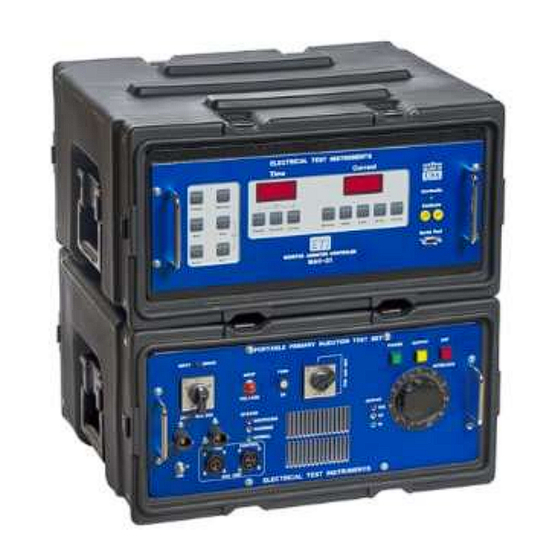
Summary of Contents for ETI PI-800-GEN2
- Page 1 PRIMARY INJECTION CIRCUIT BREAKER TEST SET INSTRUCTION MANUAL Models PI-800-GEN2 and PI-1600-GEN2 Electrical Test Instruments, LLC 8430 Spires Way, Suite A Frederick, MD 21701 www.etiprecision.com p (410) 857-1880 f (410) 857-1387...
-
Page 2: Table Of Contents
Electrical Test Instruments PI-800 GEN2 and PI-1600 GEN2 TABLE OF CONTENTS SECTION I: GENERAL INFORMATION and SPECIFICATIONS WARNING Introduction General Description Monitor and Controller MAC-21 Advantages Compared to Other Test Sets Trademarks MAC-21 Specifications PI-800 GEN2 Specifications PI-1600 Specifications SECTION II: DETAILED DESCRIPTION Theory of Operation High Current Test Sets II-1... - Page 3 Electrical Test Instruments PI-800 GEN2 and PI-1600 GEN2 Ratioing Current Transformers IV-17 SECTION V: SERVICE INFORMATION AND DOCUMENTATION Maintenance and Calibration of PI-800 GEN2/1600 Maintenance and Calibration of MAC-21 Parts List (PI-800 GEN2) Parts List (PI-AUX) Warranty Overall Schematics Copyright© 1994-2021 Electrical Test Instruments, LLC.
-
Page 4: Section I: General Information And Specifications
Electrical Test Instruments PI-800 GEN2 and PI-1600 GEN2 SECTION I GENERAL INFORMATION and SPECIFICATIONS WARNING WARNING READ THIS ENTIRE MANUAL THOROUGHLY FAMILIARIZE YOURSELF WITH THE UNIT OPERATION PRIOR TO CONNECTING THE UNIT TO A SOURCE OF POWER. HIGH CURRENT TEST SETS ARE NORMALLY POWERED FROM HIGH CAPACITY 208 VOLT TO 575 VOLT SERVICES, AND IMPROPER CONNECTION OR OPERATION COULD CAUSE DAMAGE TO THE TEST SET AND... -
Page 5: Introduction
Electrical Test Instruments PI-800 GEN2 and PI-1600 GEN2 INTRODUCTION A primary injection test set, such as the PI-800 GEN2 and PI-1600 GEN2, is a device with high current, low voltage AC outputs for testing direct acting low voltage circuit breakers. Current is injected through the main contacts of the breaker to simulate actual fault conditions, which tests the operation of CTs, solid state, thermal, or electromechanical trip devices, and the actual trip mech- anisms and breaker contacts. - Page 6 Electrical Test Instruments PI-800 GEN2 and PI-1600 GEN2 configuration bars are slotted for quick and easy changing for various breaker sizes. The PI-Aux is a booster unit which connects to the PI-800 GEN2 and MAC-21 to create a powerful two-piece test system for medium size air drawout and molded case breakers up to 1600 amperes frame size.
- Page 7 Electrical Test Instruments PI-800 GEN2 and PI-1600 GEN2 PI-800 GEN2 or PI-Aux to provide 7 ranges of output for the PI-1600 GEN2 com- bined unit. The indicator/control panel features: (1) An Input Voltage indicator, which lights whenever power is connected to the test set (2) A green Control Power ON switch/indicator, which also turns on the main output power...
-
Page 8: Monitor And Controller Mac-21
Electrical Test Instruments PI-800 GEN2 and PI-1600 GEN2 The entire test set has been designed for reliability, ruggedness, reasonable portability, and ease of use. Sophisticated electronics in the MAC-21 provide state of the art accuracy and convenience, while simple connections allow for easy disassembly for transportation or service. -
Page 9: Advantages Compared To Other Test Sets
Electrical Test Instruments PI-800 GEN2 and PI-1600 GEN2 ADVANTAGES COMPARED TO OTHER TEST SETS Several changes have been made in the design of high current test sets since early models such as the EIL BTS-50, many of which are important for safety and convenience of operation. - Page 10 Electrical Test Instruments PI-800 GEN2 and PI-1600 GEN2 MAC-21 Monitor Ammeter Controller CURRENT RANGES: 0-1000 A / 5 kA / 25 kA / 100 kA CURRENT ACCURACY: +/- 0.5% of reading + 0.5% Full Scale (Continu- ous) +/- 1% of reading + 1% Full Scale (Pulse) TIMER RANGES: 0-9999.999 Seconds / 0-9999.9 Cycles TIMER ACCURACY:...
- Page 11 Electrical Test Instruments PI-800 GEN2 and PI-1600 GEN2 PI800 GEN2 OPTION A INPUT SUPPLY: 120 or 240 VAC + 10%, -15% (Switch Selectable), SINGLE PHASE 60 HZ (50 Hz at 10% lower maximum line voltages) 4.2 KVA (Continuous) at 3.8 KVA output (90% efficiency) PI-800 GEN2 OUTPUT CURRENT &...
- Page 12 Electrical Test Instruments PI-800 GEN2 and PI-1600 GEN2 PI-1600 GEN2 Option A INPUT SUPPLY: 240 VAC + 10%, -15%, SINGLE PHASE 60 HZ (50 Hz at 10% lower maximum line voltages) 9.8 KVA (Continuous) at 8.8 KVA output (90% efficiency) (Note: Specifications include required PI-800 GEN2 unit) PI-1600 GEN2 OUTPUT CURRENT &...
-
Page 13: Section Ii: Detailed Description
Electrical Test Instruments PI-800 and PI-1600 SECTION II DETAILED DESCRIPTION THEORY OF OPERATION High Current Test Sets High current test sets generally consist of the following: 1. One or more coarse taps accomplished by: (a) A tapped autotransformer providing several equal steps of volt- age or (b) A multi-section output transformer 2. - Page 14 Electrical Test Instruments PI-800 GEN2 and PI-1600 GEN2 incorrect connection. The input voltage selector switch S1 sets the primary windings of transformer. When the control power switch S3 on the front panel is pressed, and all voltage interlocks are OK, relay K4 is energized, which provides 120 VAC control power to the entire test set.
-
Page 15: Pi-Aux Boost Unit Circuitry
Electrical Test Instruments PI-800 GEN2 and PI-1600 GEN2 PI-Aux Boost Unit Circuitry The PI-Aux Boost Unit connects to the PI-800 GEN2 to form the PI-1600 GEN2. SCR controlled voltage from the PI-800 GEN2 is distributed to the four tap relays K1-K4, which provide power to the primaries of T1-T4 when energized. - Page 16 Electrical Test Instruments PI-800 GEN2 and PI-1600 GEN2 moderate heating. A Yellow+ Red LED indicates significant heating, and heavy testing should be postponed until unit cools to Yellow. A Red LED indicates se- vere overheating, and the unit will soon trip the interlock. Allow the test set to cool to Red + Yellow range before testing.
- Page 17 Electrical Test Instruments PI-800 GEN2 and PI-1600 GEN2 MEMORY AMMETER CONTROLLER MAC-21 INSTRUCTION MANUAL Firmware Version 3.06 and above Electrical Test Instruments, LLC 8430 Spires Way, Suite A Frederick, MD 21701 www.etiprecision.com p (410) 857-1880 f (410) 857-1387 Copyright© 1994-2021 Electrical Test Instruments, LLC.
-
Page 18: Mac-21 Specifications Iii-1
Electrical Test Instruments PI-800 GEN2 and PI-1600 GEN2 MAC-21 Specifications INPUT POWER: 120 VAC, SINGLE PHASE 50/60 HZ, 20 VA Max CURRENT RANGES: 0-1,000 / 5,000 / 25,000 / 100,000 Amperes CURRENT ACCURACY: +/- 0.5% Reading + 0.5% Range + 1 Digit (Continuous) +/- 1.0% Reading + 1.0% Range + 1 Digit (Pulse >... - Page 19 Electrical Test Instruments PI-800 GEN2 and PI-1600 GEN2 MAJOR PARTS IDENTIFICATION AND OPERATION MAC-21 Control Panel TIME DISPLAY: This 4-digit LED display normally indicates the elapsed time of a cur- rent pulse. In SECONDS mode, it displays time up to 9.999 seconds, then auto ranges to 99.99 seconds, 999.9 seconds, and 9999 seconds.
- Page 20 Electrical Test Instruments PI-800 GEN2 and PI-1600 GEN2 that this mode is enabled. When in MAINTAIN mode, the INITIATE key need only be pressed briefly to turn output on. MAINTAIN must be set in order to read pulse cur- rent when output is initiated by means other than the MAC-21. For test sets with motorized vernier, the MAINTAIN key may be pressed while output is ON to provide automatic current hold.
- Page 21 Electrical Test Instruments PI-800 GEN2 and PI-1600 GEN2 be turned off within 200 milliseconds of the limit. SECONDS or CYCLES time base may be selected at any time before, during, or after a test. CYCLES key: This key normally selects the CYCLES time base. If the PRESET mode is selected, this key is used to RAISE the preset time limit by increments of 1.000 sec- onds (5.000 seconds above 10.00) with the SECONDS time base, or 1.0 cycles with the CYCLES time base.
- Page 22 Electrical Test Instruments PI-800 GEN2 and PI-1600 GEN2 preset value is set in CYCLES time base. SERIAL port: This standard serial port may be connected to a printer, computer, or other device to print or store time and current values of test results in ASCII format. It is set for 9600 baud, 8 bits, 1 stop bit, no parity, no flow control.
-
Page 23: Mac-21 Internal Parts Iii-8
Electrical Test Instruments PI-800 GEN2 and PI-1600 GEN2 MAC-21 Internal Parts INPUT CONNECTOR: This connector, located on the upper rear corner of the MAC-21, provides 120 VAC control power, and connects to the air core CT (current sensor), and initiate circuitry of the test set and is designed to facilitate removal of the MAC-21 for service or shipment. -
Page 24: Maintenance And Calibration Of Mac-21
Electrical Test Instruments PI-800 GEN2 and PI-1600 GEN2 SERVICE INFORMATION AND DOCUMENTATION MAINTENANCE AND CALIBRATION OF THE MAC-21 The MAC-21 is manufactured using solid state components that should not re- quire extensive maintenance. However, the accuracy of the MAC-21 is critical to the testing of circuit breakers and is dependent upon the output of an air-core current sensing coil, which could change due to movement caused by shock or vibration encountered in transporting the test set. -
Page 25: Parts List (Mac-21) Iii-12
Electrical Test Instruments PI-800 GEN2 and PI-1600 GEN2 accuracy, adjust the gain potentiometer on the analog board for proper reading. If an error of more than 5% is noted, and unit has been in service, the accuracy and validity of previous tests may be questionable; otherwise, there may be a problem in the test setup. - Page 26 Electrical Test Instruments PI-800 GEN2 and PI-1600 GEN2 4 NYLON WASHERS #10 M-A155 2 JACKSCREW, .312, W/HARDWARE M-A125 4 SCREW, PH, 6-32x1/4 M-A139 1 COMMUNICATION CABLE S-A106 Connections (MAC-21): Copyright© 1994-2021 Electrical Test Instruments, LLC. All Rights Reserved III-13...
-
Page 27: Section Iv: Operating Instructions
Electrical Test Instruments PI-800 GEN2 and PI-1600 GEN2 SECTION IV OPERATING INSTRUCTIONS PRE-TEST INSTALLATION AND SET-UP The following components of the test set should be available and in good condition: a) PI-800 GEN2 Main Unit b) PI-AUX Booster Unit (If required for PI-1600 GEN2) c) MAC-21 Remote d) Stab set or cables to match breaker to be tested e) Input power plugs and cables... - Page 28 Electrical Test Instruments PI-800 GEN2 and PI-1600 GEN2 For PI-1600 GEN2, place PI-800 GEN2 on top of PI-AUX Boost Unit, plug power and control cables into jacks on PI-800 GEN2. Connect inner output terminals with M-D175 connection bars per diagram. Verify proper vertical alignment before tightening and secure latches.
- Page 29 Electrical Test Instruments PI-800 GEN2 and PI-1600 GEN2 20 V @ 400 A 5 V @ 1600 A 10 V @ 800 A Output Low Output High 1 (GND) 1 (GND) 1 (GND) 400 A M-D166 M-D166 M-D166 1600 1600 1600 1600 Output Connection...
-
Page 30: Basic Guidelines And Suggestions
Electrical Test Instruments PI-800 GEN2 and PI-1600 GEN2 BASIC GUIDELINES AND SUGGESTIONS 1. Best timing and current accuracy will be obtained with the MAC-21 in cur- rent latch (C.L.) mode. 2. Current Latch modes are preferred for most testing purposes. Exceptions are: a) Non-series-connected devices such as motor overload relays or shunt- trip breakers. - Page 31 Electrical Test Instruments PI-800 GEN2 and PI-1600 GEN2 times the true continuous current for a maximum of 15 to 30 minutes, followed by an equal amount of time for cooling. This is generally a reasonable duty cy- cle for circuit breaker testing. A circuit breaker rated at the true continuous rating of a test set is usually tested for long time trip at 3x, where trip times of 30-120 seconds are common.
-
Page 32: Single Pole Molded Case Breakers
Electrical Test Instruments PI-800 GEN2 and PI-1600 GEN2 overload trip or test set damage. It is also important to note that a severely overheated test set may not pro- duce as much instantaneous current as it will when cool, due to higher re- sistance of copper buswork when hot. - Page 33 Electrical Test Instruments PI-800 GEN2 and PI-1600 GEN2 16. Read and record trip current and trip time. Compare to manufacturer's time/current curve. 17. If test is to be repeated, make sure that breaker cools completely. 18. Shut down test set, disconnect breaker, and prepare for subsequent test- ing or relocation according to steps 19 through 23 in pre-test installation and setup outlined above.
-
Page 34: Multi-Pole Molded Case Breakers
Electrical Test Instruments PI-800 GEN2 and PI-1600 GEN2 Instantaneous Trip Time Test Perform Instantaneous Pickup Test as outlined above. 2. Adjust controls to obtain current above pickup, at approximate desired multiple of rating. 3. Close breaker under test. 4. Press the INITIATE button. Breaker should trip instantaneously. 5. - Page 35 Electrical Test Instruments PI-800 GEN2 and PI-1600 GEN2 14. If desired, N.C. mode may be used; connect contacts leads to an unused pole of the breaker. 15. Press and release INITIATE key; OUTPUT ON light should glow, timer should run, and current display should read desired output current. 16.
- Page 36 Electrical Test Instruments PI-800 GEN2 and PI-1600 GEN2 11. By repeating the test, determine the MINIMUM SETTING of the OUTPUT CONTROL, at which the breaker under test opens immediately, whenever the INITIATE button is depressed. 12. Read and record ammeter reading as instantaneous pick-up of the breaker.
-
Page 37: Low Voltage Power Breakers
Electrical Test Instruments PI-800 GEN2 and PI-1600 GEN2 LOW VOLTAGE POWER CIRCUIT BREAKERS Nearly all low voltage power circuit breakers are multi-pole devices. The trip units may be either magnetic with a dash pot or solid-state electronic devices. Test procedures would be the same for either type. However, electronic trip types may incorporate ground fault protection. - Page 38 Electrical Test Instruments PI-800 GEN2 and PI-1600 GEN2 precautions and expected test results. A test current of three times the rat- ing of the breaker should be used for this test. 2. Follow steps 1 through 17 in pre-test installation and setup, as required, to set up the breaker test set.
- Page 39 Electrical Test Instruments PI-800 GEN2 and PI-1600 GEN2 Timing Test, Short Time Delay Note: The breaker's trip time for short time delay will always be less than 30 cy- cles and may be as low as 4-5 cycles. Therefore, setting test current will require some practice.
- Page 40 Electrical Test Instruments PI-800 GEN2 and PI-1600 GEN2 Consult breaker manufacturer's literature to determine any necessary pre- cautions and expected test results. Note: If the instantaneous setting is such that the expected test result is above that which may be easily pro- duced by the test set, a valid test may be performed by adjusting the set- ting to its minimum value.
-
Page 41: Motor Overload Relays
Electrical Test Instruments PI-800 GEN2 and PI-1600 GEN2 4. Press the INITIATE button. Breaker should trip instantaneously. Read and record timer and ammeter readings as instantaneous trip time and current. Repeat the above test for the other poles of the circuit breaker. Shut down test set, disconnect breaker, and prepare for subsequent test- ing or relocation according to steps 19 through 23 in pre-test installation and setup outlined above. - Page 42 Electrical Test Instruments PI-800 GEN2 and PI-1600 GEN2 10. Connect the relay control circuit contacts to the CONTACTS terminals and determine that they are closed by observing the CONTINUITY lamp. 11. Repeatedly jog the INITIATE button, while adjusting the OUTPUT CONTROL higher, until the desired test current is read on the ammeter.
- Page 43 Electrical Test Instruments PI-800 GEN2 and PI-1600 GEN2 RATIOING CURRENT TRANSFORMERS To conduct a ratio test on a current transformer, a good multi-range bench ammeter is required in addition to the breaker test set. The breaker test set supplies primary current to the transformer and the bench ammeter is used to read the transformer secondary current.
- Page 44 Electrical Test Instruments PI-800 GEN2 and PI-1600 GEN2 SECTION V SERVICE INFORMATION AND DOCUMENTATION MAINTENANCE AND CALIBRATION OF THE PI-800 GEN2 and PI-1600 GEN2 The PI-800 GEN2 and PI-1600 GEN2 require only minimal maintenance. Mechanical components such as latches may need periodic lubrication. External surfaces should be kept clean, and screws on access panels should be checked for tightness.
- Page 45 Electrical Test Instruments PI-800 GEN2 and PI-1600 GEN2 intervals and adjusted if proper equipment is available. The manufacturer’s rec- ommended calibration interval is (1) one year. The inherently delicate nature of electronic circuitry and metering make it gen- erally inadvisable to leave the MAC-21 fastened to the breaker test set if it is be- ing transported under conditions of extreme shock and vibration.
- Page 46 Electrical Test Instruments PI-800 GEN2 and PI-1600 GEN2 The meter should read the same value, within 2%, that was set in step 11 above. 14. Check pulse reading operation in this manner for currents of 200, 400, 600, and 1000 Amperes, and varying duration. 15.
- Page 47 PARTS LIST (PI-800 GEN2): The overall schematic is at the end of the manual. The parts list is provided below. Please refer to both when ordering replacement parts. ITEM DESCRIPTION REF DES ETI Number Contactor, 4PST, 30A M-C197 Contactor, 2NO2NC, 20A K2-K3 M-C196...
- Page 48 Electrical Test Instruments PI-800 GEN2 and PI-1600 GEN2 PARTS LIST (PI-AUX): The overall schematic is at the end of the manual. The parts list is provided below. Please refer to both when ordering replacement parts. ITEM QTY DESCRIPTION REF DES Part Number Contactor, 2NO2NC, 20A K1-K4...
- Page 49 Electrical Test Instruments PI-800 GEN2 and PI-1600 GEN2 PI-800 GEN2 Output Connections 4.5 Volt 800 Amp Copyright© 1994-2021 Electrical Test Instruments, LLC. All Rights Reserved...
- Page 50 Electrical Test Instruments PI-800 GEN2 and PI-1600 GEN2 PI-800 GEN2 Output Connections 9 Volt 400Amp Copyright© 1994-2021 Electrical Test Instruments, LLC. All Rights Reserved VI-7...
- Page 51 Electrical Test Instruments PI-800 GEN2 and PI-1600 GEN2 PI-1600 GEN2 Output Connections 10 Volt 800Amp Copyright© 1994-2021 Electrical Test Instruments, LLC. All Rights Reserved VI-8...
- Page 52 Electrical Test Instruments PI-800 GEN2 and PI-1600 GEN2 PI-1600 GEN2 Output Connections 5 Volt 1600Amp Copyright© 1994-2021 Electrical Test Instruments, LLC. All Rights Reserved VI-9...
- Page 53 Electrical Test Instruments PI-800 GEN2 and PI-1600 GEN2 WARRANTY Electrical Test Instruments, LLC, will correct any defect in workmanship or material for two years after date of purchase of any Electrical Test Instruments product. Such corrective measures will be limited to repairing or replacing the unit, at Electrical Test Instruments' option.
Need help?
Do you have a question about the PI-800-GEN2 and is the answer not in the manual?
Questions and answers