Advertisement
setup/status switch
Connect to main
chassis ground
+12V
KEY ON POWER
(fused 5 - 20 AMP max)
This Bus Interface Module has inputs for up to five solid state pressure sensors. Each input can be configured
individually. There are two interface (I/O) ports on the module. Either one can be connected to the gauge system or to
another module, allowing several units to be daisy chained together. Do not connect the I/O port to anything other
than a Dakota Digital gauge or BIM. Do not mount the module in the engine compartment; it should be mounted in
interior of the vehicle.
Each sensor connected to the bus needs a unique ID number assigned to it. This module has five inputs so it can use
one, two, three, four, or five ID numbers. The module is assigned an ID from 1 – 16 or turned off and will auto detect
how many sensors are connected and use additional ID's as needed. The factory default ID numbers are 12 – 16 with
all five sensors connected.
Air Ride setup options:
4 bag
LR
-
LEFT REAR
RR
-
RIGHT REAR
LF
-
LEFT FRONT LEFT FRONT FRONT
RF
-
RIGHT FRONT RIGHT FRONT not connected not connected
TNK
-
TANK (optional for all bag setups)
Specs for each input are:
Part #
Range
SEN-03-9
0 - 300psi
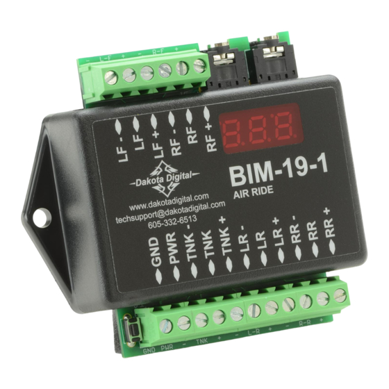
Bus Interface Module for air ride pressure
(Sensors are sold separately)
To gauge control box
or another BIM
BIM-19-1
www.dakotadigital.com
AIR RIDE
techsupport@dakotadigital.com
605-332-6513
3 bag
REAR
not connected not connected RIGHT
resolution
1
BIM-19
Front/Rear
Left/Right
REAR
LEFT
not connected
low warning
high warning
0 – 252
48 – 300
Left Front pressure sensor
Right Front pressure sensor
Right Rear pressure sensor
Left Rear pressure sensor
Tank pressure sensor
MAN#650346
Advertisement
Table of Contents

Related Manuals for Dakota Digital BIM-19


Summary of Contents for Dakota Digital BIM-19
- Page 1 Do not connect the I/O port to anything other than a Dakota Digital gauge or BIM. Do not mount the module in the engine compartment; it should be mounted in interior of the vehicle.
- Page 2 To set or change the ID numbers: • Hold the switch beside the BIM terminal strip while turning the key on. The BIM display will show the current revision code while this is held. • Release the switch. The display will show “-C-”. •...
- Page 3 Troubleshooting quick tips: While the BIM is operating, the dot in the upper left corner of the display will indicate the status. On steady indicates it is powered up but not receiving any bus activity. Flashing indicates it is communicating on the bus. To see the sensor and channel status on the BIM display, press and hold the switch.
- Page 4 Dakota Digital’s option. This warranty does not cover nor extend to damage to the vehicle’s systems, and does not cover removal or reinstallation of the product.
Need help?
Do you have a question about the BIM-19 and is the answer not in the manual?
Questions and answers