
Related Manuals for Haier AH1-070B


Summary of Contents for Haier AH1-070B
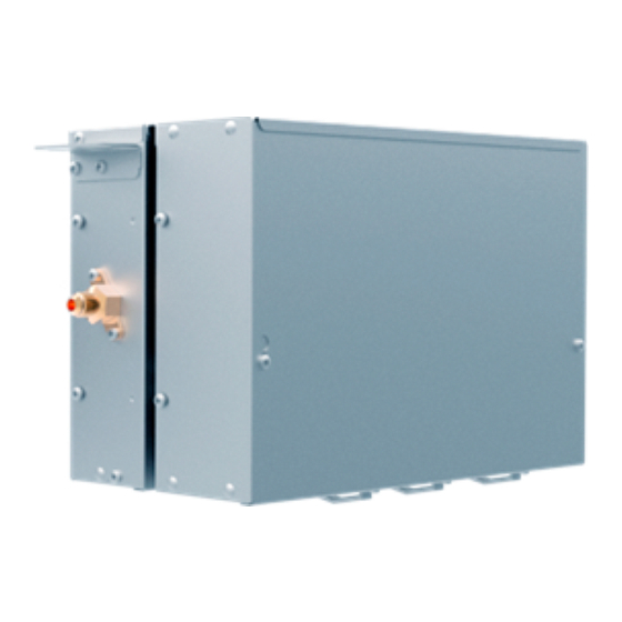
- Page 1 AHU Valve Box AH1-070B AH1-140B AH1-280B AH1-560B AH1-730B SYJS-07-2020REV.C Edition: 2020-07...
-
Page 2: Table Of Contents
Content 1.General information.........................1 2. Specification ...........................3 3. Combination method ......................4 4. Dimension ..........................6 5. Wiring diagram ........................8 6.Installation ..........................9 7.PCB photo ..........................29 8. Dip switch setting .........................30 9. Failure code .........................38 10.Troubleshooting ........................39 11.Sensor resistance table .......................43... -
Page 3: General Information
1.General information 1.1 Function: Thought AHU valve box, can realize the haier MRV outdoor unit connect with third party air handling units. As the following figure 1.2 Feature (1) (1) EXV part and control part integration, easy for translation and installation. Gas pipe is cancelled compared to the previous generation. - Page 4 1.3 System lineup Haier AHU kit provides a wide range solution for Haier MRV outdoor unit connecting with the 3rd party AHU Compatibility Outdoor MRV5 MRV SII 8-26 1Ph/220-230Ph/50/60Hz 3Ph/380- Power Supply 3Ph/380-400V/50/60Hz 415V/50/60Hz 3Ph/380-400V/50/60Hz 1.4 Configuration AH1-070B/AH1-140B/AH1-280B AH1-560B/AH1-730B 1.5 Nomenclature Code 1,2...
-
Page 5: Specification
2. Specification Model AH1-070B/140B AH1-280B AH1-560B/730B 3 <x ≤7KW(070B) 8 < x ≤56KW(560B) Connected AHU capacity 14 < x ≤28KW(5-10HP) 7 x ≤14KW(140B) 56 < x ≤73KW(730B) Power supply 220-240V/50/60Hz 220-240V/50/60Hz 220-240V/50/60Hz Dimention(W/D/H) 420/260/165 420/260/165 420/260/165 Shipping dimensions 520*340*225 520*340*225... -
Page 6: Combination Method
3. Combination method Capacity Combination model 3≤x≤7KW AH1-070B 7<x≤14KW AH1-140B 14<x≤28KW AH1-280B 28<x≤56KW AH1-560B 56<x≤73KW AH1-730B 73<x≤112KW AH1-560B+AH1-560B 112<x≤146KW AH1-730B+AH1-730B 146<x≤168KW AH1-560B+AH1-560B+AH1-560B 168<x≤219KW AH1-730B+AH1-730B+AH1-730B 219<x≤224KW AH1-560B+AH1-560B+AH1-560B+AH1-560B 224<x≤292KW AH1-730B+AH1-730B+AH1-730B+AH1-730B Note: The above is the combination method for single heat exchanger, when multiple heat exchangers need to be... - Page 7 AH1-070B AH1-140B AH1-280B AH1-560B AH1-730B Capacity 3.6-7.1 7.1-14 14-28 28-56 56-73.5 fan Air 540/1420/1775 1065/2800/3500 2100/5600/7000 4200/11200/14000 8400/14700/18375 volumem3/h Coil qty. 4-14 6-26 12-32 Coil volume L 0.54-1.28-1.42 1.07-2.52-2.8 2.1-5.04-5.6 4.2-10.08-11.2 8.4-13.23-14.7...
-
Page 8: Dimension
4. Dimension AH1-070B AH1-140B AH1-280B... - Page 9 AH1-560B AH1-730B...
-
Page 10: Wiring Diagram
5. Wiring diagram... -
Page 11: Installation
6.Installation Parts and function AH1-070B AH1-140B AH1-280B Outdoor unit side Indoor unit side Liquid Pipe (Ø9.52) Liquid Pipe (Ø9.52) AH1-560B AH1-730B Indoor unit side Outdoor unit side Liquid Pipe (Ø12.7) Liquid Pipe (Ø12.7) Safety • f the connection kit is transferred to a new user, this manual shall be transferred to the user, together with the conditioner. - Page 12 Warning • lease ask the special maintenance station for installation and repair. Water leakage, electric shocks or fire accidents might be caused from improper installation if you conduct the installation by your own. • he installation should be conducted properly according to this manual. Water leakage, electric shocks or fire accidents might be caused from improper installation.
- Page 13 • his appliance is not intended for use by persons (including children) with reduced physical, sensory or mental capabilities, or lack of experience and knowledge, unless they have been given supervision or instruction concerning use of the appliance by a person responsible for their safety. •...
- Page 14 Do not apply force to other parts, especially a refrigerant tube and an electrical cabinet. • Concerning the installation of the outdoor and indoor units, refer to the installation specification of each unit. Accessories Confirm that the accessories below are packed together. AH1-070B, AH1-140B, AH1-280B Variable Thermal suspending...
- Page 15 • Please according to the following table to select the connection kit model. Table1: Total capacity of indoor unit: Connection kit The capacity of the air handing unit (kW) The quantity of the air handing unit AH1-070B 3≤x≤7KW (1-3HP) AH1-140B 7<x≤14KW (3-5HP) AH1-280B 14<x≤28KW (5-10HP)
- Page 16 6.4 Installation procedure 6.4.1. Pre-installation The installation location selected shall meet the following conditions and be approved by users. • The strength shall be sufficient to withstand the weight of the connection kit • There is no significant tilt on the plane. •...
- Page 17 Dividually mounted (mm) Max 5000 Electrical box Connection kit Manhole must be arranged Electrical box on the side of the electrical 6.4.2. Preparation before installation (1) Connection kit dimension (mm) AH1-070B AH1-140B AH1-280B...
- Page 18 AH1-560B AH1-730B (2) Lifting dimension of connection kit (mm) AH1-070B AH1-140B AH1-280B AH1-560B AH1-730B Fig.1...
- Page 19 Foundation bolt Thick cement plate Long nuts or turnbuckle Lifting tools Lifting bolt Connection Less than 1m Less than 1m Note: All the parts in the figure are purchased locally. Fig.2 See the Fig.1 & Fig.2 to install the lifting bolts and hoisting tools. •...
- Page 20 Install the lifting tools on the lifting bolts according to the instruction of the Fig.2 Be sure to follow the stipulations on products locally purchased to use nuts (M8 or M10 of 3 pieces for 4 positions) and gaskets (M8 with the outer diameter of 24~28 mm and M10 with that of 30~34 mm of 2 pieces for 4 positions) on the upper and lower sides of the lifting tools.
- Page 21 The high-pressure gas pipe, suction gas pipe, liquid pipe must be provided with reliable thermal insulation. In the Paste the refrigerant oil here absence of thermal insulation, liquid leakage may happen. The outdoor unit is already filled with refrigerant. To connect the pipes to connection kit or remove them from connection kit, Torque spanner do use both spanner and torque wrench, as shown in the Fig.1.
- Page 22 Piping maintenance During installation, provide maintenance as specified in the table in order to prevent water, foreign matter and dust from entering the pipes. Location Work period Maintenance method More than 1 month Screw Outdoors Less than 1 month Screw or strap Indoors ——...
- Page 23 Select refrigerant branching dimensions between outdoor units and connection kit, between connection kit and indoor units according to the Operation & Installation Manual of outdoor units and indoor units. Dimensions (mm) of connection pipe of the vale box Dimension (outer diameter) model Liquid pipe / convertible dimension AH1-070B AH1-140B Ø6.35/Ø9.52 AH1-280B AH1-560B Ø12.7/Ø15.88...
- Page 24 Pipe connection Piping specifications Indoor Outdoor When the connection kit and the piping specifications are not the same, can import and conversion by variable diameter. (the transfer pipe size selection see accessories) Pipe insulation Please use the auxiliary insulation cylinder and tie wire for insulation works according to Fig.1 after the gas leakage test.
- Page 25 6.6 Temperature Sensor Installation (1) TC2 sensor should be attached after the distributor, on the coldest part of the heat exchanger pipe. (2) TC1 sensor should be installed approximately 200mm behind the header of AHU heat exchanger. (3) TC1/2 sensor should be insulated for optimized system performance. (4) Room temperature sensor should be installed where room air enters.
- Page 26 6.7 Electrical wiring Warning • Electrical construction should be made with specific mains circuit by the qualified personnel according to the installation instruction. Electric shock and fire may be caused if the capacity of power supply is not sufficient. • During arranging the wiring layout, specified cables should be used as the mains line, which accords with the local regulations on wiring.
- Page 27 The wiring for the power line and signal line of connection kit • Power cable and communication wire must be fixed firmly. • Each connection kit must be earthed well. • When power cable exceeds the range, thicken it appropriately. •...
- Page 28 Notes: (1) The above wiring example is only for reference. The number of connection kits and indoor units shall be subject to the field installation. (2) Two-core non-polar communication line with shield shall be adopted for communication lines between the connection kit and the indoor/outdoor unit.
- Page 29 Wiring connection Refer to the wiring diagram of electrical wiring of a connection kit – for wiring connection of connection kit. (1) Connection communication line Remove the cover of the electrical cabinet of the valve cage. Introduce communication lines for outdoor and indoor units to the through holes at the lower right of the electrical cabinet and crimp them on the communication terminal block respectively.
- Page 30 (3) Electrical specifications Power supply 1PH,220-240V~,50/60Hz Power consumption 2.54-3.5 Power supply current 0.02 Power supply breaker Power supply cable 3x 1.5mm² Communication cable 2x0.75mm² shielded line Gas pipe sensor, Use the configurated sensor by factory Thermistor Liquid pipe sensor, Use the configurated sensor by factory Use the configurated sensor by factory PMV wiring Use the configurated cable by factory...
-
Page 31: Pcb Photo
7.PCB photo '0151800545... -
Page 32: Dip Switch Setting
… … … …… 15# Slave Unit AHU Capacity SW3_5 AH1-070B Capacity SW3_8 AH1-140B AH1-280B AH1-560B/AH1-730B 2. Code setting for the postal address of the connection kit: SW2 is used for AH devices address setting, 1 is ON, 0 is OFF Manner of set Set the address with automatism (default)... - Page 33 Communication Center controller [2] [3] [4] [5] [6] [7] [8] address address SW2_2 communication address of first SW2_8 indoor unit address...
- Page 34 Communication Center controller [2] [3] [4] [5] [6] [7] [8] address address SW2_2 communication address of first SW2_8 indoor unit address … … … … … … … …… …… 126# 127# 3. Code setting for changing the control methods of connection kit: 1 is ON, 0 is OFF Control methods plan A SW1_1...
- Page 35 Haier AHU kit can provide mode signal to DDC or AHU unit PCB directly to control the AHU unit, e.g. if the DDC or 3rd party AHU unit PCB receives defrost signal from AHU kit, AHU fan motor will be controlled.
- Page 36 Haier AHU kit controls 3rd party AHU units such as the on/off, temperature settings, fan speed adjustment and operation mode etc. b) Haier AHU kit can provide mode signal to DDC or AHU unit PCB directly to control the 3rd party AHU fan motor. It’s required to output either the dry contact or strong electricity signal.
- Page 37 Connect method: 1. one by one: the plan A or plan B or plan C or plan D is avaiable 2. one outdoor with multiple AHU valves (AHU has only one coil): the plan A or plan B or plan C or plan D is avaiable , and the max. qty of AHU valve boxes is 4.
- Page 38 3. one outdoor with multiple AHU valves (AHU has multiple coils): the plan A or plan B or plan C or plan D is avaiable , and the max. qty of AHU valve boxes is 4. 4 . one outdoor with multiple AHU valves (AHU has multiple coils): the plan A or plan B or plan C is avaiable , and the max.
- Page 39 5. Mixed connetion: the plan C or plan D is avaiable . 5. Mixed connetion (multiple outdoor units with one AHU,AHU has multiple coils): Note: This connection method is not recommended.
-
Page 40: Failure Code
9. Failure code 1. Confirm that the cover of the electrical cabinet of the connection kit is of good sealing. 2. Conduct commissioning in accordance with the installation and use specification attached to the outdoor unit. At the time of energization, because electronic expansion valve will start initialization (open/ close), there may be click lasting for about 20s, which is normal. -
Page 41: Troubleshooting
10.Troubleshooting [1~3] Sensor fault If sensor If sensor resistor/characteristic is Replace valve terminal is proper and its deviation box PCB fixed well Is within ±3℃ Replace connecting sensor Replace sensor [5] Fault of connection kit EEPROM Power off and check if the Reconnet EEPROM is fixed well Replace... - Page 42 [6] Fault of communication between Connection kit & outdoor units Check if communication wire of Reconnect indoor unit is fixed well Replace Check if the communication line communication is damaged or short circuit wire Replace connection kit PCB...
- Page 43 [7] Fault of communication between connection kit and wired control Check if communication wire of Reconnect wired controller is fixed well Replace Check if the communication line communication is damaged or short circuit wire If it is normal after changed the wired controller Replace connection kit PCB...
- Page 44 [8Fault of connection kit water drainage Check if the CN13 is short circuit Short circuit CN13 [9]Fault of duplicate connection kit address Check if the valve box address is duplication with indoor units Resetting address [20] Outdoor unit fault Referring to the outdoor unit troubleshooting methods...
-
Page 45: Sensor Resistance Table
11.Sensor resistance table Model Code Description PCB socket Color Characteristic R25=23KΩ±3%, 0150401850 Ambient temp. sensor CN20 Green AH1-070B B25/50=4200K±3% AH1-140B R25=10KΩ±3%, 0150401849 TC1 sensor CN18 Green AH1-280B B25/50=3700K±3% AH1-560B R25=10KΩ±3%, 0150401848 TC2 sensor CN19 Black AH1-730B B25/50=3700K±3%... - Page 46 R25=10KΩ±3% B25/50=3700K±3% Temp resistance(KΩ) % (resist.tol) Rmax R(t)Normal Rmin MAX(+) MIN(-) (℃) 145.819 135.018 124.217 138.071 129.126 120.181 6.93 6.93 131.793 123.339 114.885 6.85 6.85 125.665 117.684 109.703 6.78 6.78 119.706 112.18 104.654 6.71 6.71 113.933 106.843 99.753 6.64 6.64 108.361 101.687 95.013...
- Page 47 13.24 12.8 12.36 3.44 3.44 12.69 12.277 11.864 3.36 3.36 12.166 11.778 11.39 3.29 3.29 11.666 11.302 10.938 3.22 3.22 11.189 10.848 10.507 3.15 3.15 10.734 10.414 10.094 3.07 3.07 10.3 9.898 9.604 9.31 3.06 3.06 9.514 9.226 8.938 3.13 3.13 9.147 8.864...
- Page 48 2.021 1.91 1.799 5.81 5.81 1.958 1.849 1.74 5.88 5.88 1.897 1.791 1.685 5.94 5.94 1.839 1.735 1.631 1.782 1.68 1.578 6.06 6.06 1.728 1.628 1.528 6.13 6.13 1.676 1.578 1.48 6.19 6.19 1.626 1.53 1.434 6.25 6.25 1.578 1.484 1.39 6.31 6.31...
- Page 49 R25=23KΩ±3% B25/50=4200K±3% Temp resistance(KΩ) % (resist.tol) Rmax R(t)Normal Rmin MAX(+) MIN(-) (℃) 538.771 513.115 487.459 502.577 478.894 455.211 4.95 4.95 469.29 447.408 425.526 4.89 4.89 438.613 418.379 398.145 4.84 4.84 410.288 391.564 372.84 4.78 4.78 384.088 366.751 349.414 4.73 4.73 359.817 343.754 327.691...
- Page 50 31.385 30.671 29.957 2.33 2.33 29.874 29.21 28.546 2.27 2.27 28.445 27.828 27.211 2.22 2.22 27.095 26.521 25.947 2.16 2.16 25.816 25.283 24.75 2.11 2.11 24.606 24.111 23.616 2.05 2.05 23.46 22.54 22.396 21.947 21.498 2.04 2.04 21.386 20.949 20.512 2.09 2.09 20.429...
- Page 51 3.72 3.578 3.436 3.97 3.97 3.591 3.452 3.313 4.01 4.01 3.466 3.331 3.196 4.06 4.06 3.347 3.215 3.083 3.233 3.104 2.975 4.14 4.14 3.122 2.997 2.872 4.19 4.19 3.017 2.895 2.773 4.23 4.23 2.918 2.798 2.678 4.28 4.28 2.821 2.704 2.587 4.32 4.32...
- Page 52 Haier Commercial Air Condition ADDRESS: No.1 Haier Road, Hi-tech Zone,Qingdao 266101 P.R.China Web: Http://www.haier.com Haier reserves the right to make change without any notice.