
Related Manuals for Siemens GMSG


Summary of Contents for Siemens GMSG
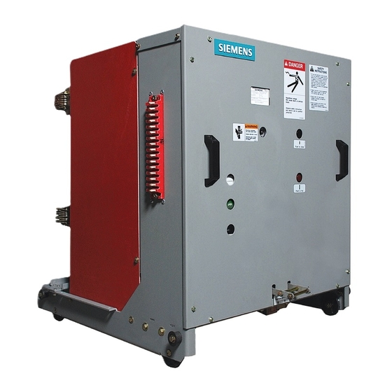
- Page 1 Type GMSG 5 kV to 15 kV vacuum circuit breaker instruction manual Installation operation maintenance E50001-F710-A231-X-4A00 Answers for energy.
- Page 2 50 volts equipment purchased. Siemens reserves or more, and shall, at a minimum, be the right to make changes in the additionally trained in all of the following:...
-
Page 3: Table Of Contents
The sales contract contains Overhaul 53 - 58 the entire obligation of Siemens Energy, Inc. The warranty contained in the contract between the parties is the sole warranty of Maintenance and troubleshooting 59 - 61 Siemens Energy, Inc. -
Page 4: Introduction
Introduction Caution (without safety alert symbol) - Indicates a potentially hazardous situation The GMSG family of vacuum circuit which, if not avoided, may result in breakers is designed to meet all applicable property damage. ANSI, NEMA and IEEE standards. Successful... - Page 5 Introduction Field service operation and warranty issues Siemens can provide competent, well trained field service representatives to provide technical guidance and advisory assistance for the installation, overhaul, repair and maintenance of Siemens equipment, processes and systems. Contact regional service centers, sales...
-
Page 6: Receiving, Handling And Storage
This portion of the instruction manual protected from the elements. Note the covers the receiving, handling and storage trailer number the equipment arrived instructions for a type GMSG vacuum on. Note also any blocking of circuit breaker shipped separately from the equipment. During unloading, check switchgear. - Page 7 Siemens cannot be held liable for repairs. Siemens will not be held liable for repairs 6. Be sure the equipment is properly in any case where repair work was protected from any further damage by performed prior to authorization from covering it properly after unloading.
- Page 8 Manual open/trip button temperature variations. Outdoor storage Figure 1: Type GMSG vacuum circuit breaker front panel controls Outdoor storage is not recommended. When no other option is available, the circuit breaker must be completely covered and protected from rain, snow, dirt and all other contaminants.
-
Page 9: Installation Checks And Functional Tests
Read instruction manuals, observe safety instructions and use qualified personnel. Spring-discharge check Introduction Refer to Figure 1: Type GMSG vacuum This section provides a description of the circuit breaker front panel controls on inspections, checks and tests to be page 8. - Page 10 11). This action operates the unit. racking-interlock latch. Figure 2: Type GMSG vacuum circuit breaker racking Removal from cell in outdoor non-walk- on page 11 shows circuit breaker in enclosures or for indoor switchgear racking.
- Page 11 Can result in death, serious injury or property damage. Do not transport a circuit breaker using a lift truck with the lift truck in the raised position. Figure 2: Type GMSG vacuum circuit breaker racking 3. Rotate the racking crank 8.
- Page 12 Installation checks and functional tests The portion of the racking-mechanism 5. When properly engaged, the crank shaft visible is cylindrical, and the shoulder should remain connected to the of the racking-mechanism shaft is hidden racking mechanism. If the crank does by a shroud until the engagement not remain in position, adjust the procedure starts.
- Page 13 Siemens contact lubricant jumper slides into place and number 15-172-791-233. interconnects all control power and 4. The type GMSG vacuum circuit breaker signal leads (for example, electrical trip is ready for installation into its assigned and close contacts) between the cubicle of the metal-clad switchgear.
-
Page 14: Vacuum Interrupter/Operator
Vacuum interrupter/operator Figure 8: Front view of type GMSG vacuum circuit breaker with front panel removed Closing Gearbox Opening Push-to-close spring spring Secondary disconnect Auxiliary switch Spring- charging motor Close coil Trip coil CHARGED/ DISCHARGED indicator Push-to-trip OPEN/CLOSED indicator Jack shaft... - Page 15 Ceramic insulator power and an operator housing. Insulating barriers are located along the outer sides Metal bellows as shown in Figure 11: Type GMSG vacuum circuit breaker on page 17. Guide This section describes the operation of each major sub-assembly as an aid in the...
- Page 16 Vacuum interrupter/operator Stored-energy operating mechanism The stored-energy operating mechanism of the type GMSG vacuum circuit breaker is an integrated arrangement of springs, solenoids and mechanical devices designed to provide a number of critical functions. The energy necessary to close and open (trip) the contacts of the vacuum interrupters is stored in powerful tripping and closing springs.
- Page 17 (60.0). The mechanism is of the spring-stored Shown with outer-phase barriers installed energy-type and is mechanically and electrically trip-free. Figure 11: Type GMSG vacuum circuit breaker The OPEN/CLOSED indicator (58.0), CHARGED/DISCHARGED indicator (55.0) and the operations counter (59.0) are 16.0 20.0...
- Page 18 58.0 surrounding atmosphere. 59.0 Switching operation Refer to Figure 14: Type GMSG vacuum circuit breaker pole section on page 19. When a closing command is initiated, the closing spring, that was previously charged by hand or by the motor, actuates the moving contact (36.0) through jack shaft...
- Page 19 Vacuum interrupter/operator Figure 14: Type GMSG vacuum circuit breaker pole section 16.0 20.0 27.0 31.2 31.0 28.0 30.0 36.0 35.0 28.1 29.1 63.0 29.2 36.3 29.0 40.0 48.9 48.6 48.0 49.0 63.0 63.7 60.0 16.0 - Insulator 30.0 - Vacuum interrupter 48.0 - Insulating coupler...
- Page 20 Vacuum interrupter/operator Figure 15: Stored-energy operating mechanism 55.2 50.3 50.3.1 62.3 62.6 62.5 62.5.2 50.2 62.2 68.0 50.1 53.0 55.1 62.0 53.1 54.1 50.4.1 55.0 54.0 54.2 50.4 68.1 64.2 58.0 63.7 63.1 59.0 60.0 61.8 64.0 63.5 62.8 64.3 64.3.1 63.0 50.1 - Manual-spring charging port...
- Page 21 Vacuum interrupter/operator Operating mechanism Motor-operating mechanism The operating mechanism is comprised of The spring-charging motor (50.4) is bolted the mechanical and electrical components to the charging-mechanism (50.2) gear required to: box installed in the mechanism housing. Neither the gear-box mechanism nor the 1.
- Page 22 Vacuum interrupter/operator Closing Refer to Figure 15: Stored-energy operating mechanism on page 20 and Figure 16: Use of manual-spring operating 50.0 crank on page 22. 53.0 50.1 If the circuit breaker is to be closed locally, the closing spring is released by pressing the close button (53.0).
- Page 23 Vacuum interrupter/operator Trip-free functionality Manually charging the closing spring Refer to Figure 15: Stored-energy Refer to Figure 16: Use of manual-spring operating mechanism on page 20. operation crank on page 22. Trip-free functionality is accomplished by Insert the hand crank (50.0) in hole (50.1) blocking movement of the close latch pawl and turn it clockwise (about 48 (62.5.2) when the manual trip pushbutton...
- Page 24 Vacuum interrupter/operator Figure 17: Operator sequence operation diagram Closing Closed voltage applied. Anti-pumping feature (52Y) assures a continuously applied closing command does not cause the circuit breaker to reclose automatically after it has tripped out on a fault. Undervoltage device Spring-charge motor Continuous 27 picks up.
- Page 25 Vacuum interrupter/operator Figure 18: Typical elementary diagram 88 (M1) - Spring-charging motor 52a (S1) - Auxiliary switch is open when circuit breaker is open 52b (S1) - Auxiliary switch is closed when circuit breaker is closed (SD) (SD) (SD) (SD) (SD) LS3 (S3) - Anti-pump circuit is open when closing spring is charged...
- Page 26 Vacuum interrupter/operator These releases are mechanical-energy Shown charged 21.0 25.0 27.0 storage devices. Their internal springs are charged as a consequence of the circuit breaker mechanism operation. This energy 33.0 is released upon application or removal (as 23.0 31.0 appropriate) of applicable control voltages 11.0 (refer to Figure 19: Construction of secondary shunt release and Figure 20:...
- Page 27 Vacuum interrupter/operator Construction and mode of operation of secondary release and undervoltage Position A: locked release Refer to Figure 19: Construction of secondary shunt release and Figure 20: Latch details on page 26 and Figure 21: 23.0 Undervoltage lock/operate selection. 29.0 The release consists of a spring power- storing mechanism, a latching device and...
- Page 28 Following every tripping operation, the Shock absorber striker pin (23.0) must be reset to its A type GMSG vacuum circuit breaker is normal position by loading the spring (31). equipped with a sealed, oil-filled, viscous This takes place automatically via the damper or shock absorber (61.8) (refer to...
- Page 29 Vacuum interrupter/operator 1.0 Ground disconnect 4.0 Closed circuit breaker racking interlock 2.0 Racking mechanism release handle 5.0 Circuit breaker frame 3.0 Trip-free interlock 6.0 Rating interlock Figure 28: Circuit breaker interlocks and ground disconnect Figure 26: MOC switch operating arm on a circuit breaker Mechanism-operated cell (MOC) switch All circuit breakers contain the MOC-switch (optional)
- Page 30 Vacuum interrupter/operator Figure 29: Circuit breaker compartment up to 50 kA shown 10.0 11.0 12.0 1. Interface blocking plate (rating interlock) 7. MOC switch terminals 2. Racking mechanism 8. TOC switch terminals 3. Ground bar 9. Shutter-operating linkage 4. Guide rails 10.
- Page 31 The purpose of the trip-free switchgear compartment. For example, a interlock is to hold the circuit breaker type GMSG circuit breaker rated 15 kV, operating-mechanism mechanically and 50 kA interrupting and 3,000 A continuous electrically trip-free. The circuit breaker is...
- Page 32 Circuit breaker handling wheels The rating interlock prevents insertion of a lower-rated circuit breaker into a cubicle The type GMSG vacuum circuit breaker is intended for a circuit breaker of higher designed for easy movement into and out ratings, subject to the limitations detailed of the metal-clad switchgear assembly.
- Page 33 Figure 30: Interlock mechanisms on the type GMSG vacuum circuit breaker compartment. The interlock is coded to test rated voltage, as well as 2.
- Page 34 Vacuum interrupter/operator B. Trip-free interlock Figure 28: Circuit breaker interlocks and ground disconnect on page 29 shows the automatic closing spring energy released (spring dump) and Close-latch lever trip-free interlock. This interlock is a Closing-spring release cam plunger with a roller on the lower end.
- Page 35 Vacuum interrupter/operator Figure 31: Closed circuit breaker interlock mechanism in stored- energy mechanism on page 34 shows the operating mechanism detail components which establish a spring dump condition as the spring dump/trip-free interlock is actuated by the spring dump and trip-free cam profiles on the racking mechanism.
-
Page 36: Maintenance
Siemens recommends the circuit breaker intended to cover essential to safe and reliable operation of should be inspected and exercised reconditioning or major the type GMSG vacuum circuit breaker. annually. repair, but should be When the type GMSG vacuum circuit designed to reveal, if For the safety of maintenance personnel as breaker is operated under "usual service... - Page 37 Follow all safety instructions contained herein. Recommended maintenance and Recommended hand tools lubrication The type GMSG vacuum circuit breaker uses both standard SAE (U.S. customary) Periodic maintenance and lubrication and metric fasteners. Metric fasteners are should include all the tasks shown in Table 1: Maintenance tasks on page 38.
- Page 38 Maintenance Failure to maintain the equipment can result in death, serious injury, property damage or product failure, and can prevent successful functioning of connected apparatus. The instructions contained herein should be carefully reviewed, understood and followed. The maintenance tasks in Table 1 must be performed regularly. Inspection items and tests Primary-power path checks Cleanliness check...
- Page 39 DISCONNECT position. primary disconnects (barriers removed) is 4. Perform the spring discharge check. a side view of the type GMSG vacuum This is done by first depressing the red circuit breaker with the outer-insulating trip pushbutton. Second, depress the barriers removed to show the vacuum black close pushbutton.
- Page 40 GMSG 10-years/ primary disconnects, and apply a very thin 63 kA 5,000 mechanism with a dry, lint-free cloth. layer of Siemens contact lubricant operations (reference 15-172-791-233). Check all components for evidence of excessive wear. Checks of the stored-energy operator Table 2: Maintenance and...
- Page 41 Maintenance Figure 35: Operator mechanism lubrication Klüber L32 or Klüber L32N Typical for all three-phases...
- Page 42 (strips and fingers) are to be wiped clean, and a film of Siemens vacuum interrupter is nearing the limit contact lubricant (15-172-791-233) of its contact life. Determination of applied.
- Page 43 Read instruction manuals, observe safety instructions and use qualified personnel. Electrical-control checks Primary tasks of this check are: The electrical controls of the type GMSG 1. The circuit breaker is energized with vacuum circuit breaker should be checked control power for this check.
- Page 44 The vacuum interrupter type designation is labeled on the vacuum interrupter. If the vacuum interrupter installed does not match that indicated in this table, contact the nearest Siemens representative. If you need assistance achieving the indicated stroke setting, contact the nearest Siemens representative.
- Page 45 Maintenance Figure 37: Typical vacuum interrupter contact life curves Load graph "A" vacuum interrupter type VS-17006 Note: Right-hand vertical segment of curve is located at the maximum symmetrical interrupting current rating of the circuit breaker, as indicated in Table 3: Typical vacuum interrupter contact life and stroke on page 44.
- Page 46 Maintenance Figure 37: Typical vacuum interrupter contact life curves (continued) Load graph "B" vacuum interrupter type VS-17040 Note: Right-hand vertical segment of curve is located at the maximum symmetrical interrupting current rating of the circuit breaker, as indicated in Table 3: Typical Permissible operating cycles vacuum interrupter contact life and stroke on page 44.
- Page 47 Maintenance Figure 37: Typical vacuum interrupter contact life curves (continued) Load graph "C" vacuum interrupter type VS-15052 Note: Right-hand vertical segment of curve is located at the maximum symmetrical interrupting current rating of the circuit breaker, as indicated in Table 3: Typical Permissible operating cycles vacuum interrupter contact life and stroke on page 44.
- Page 48 Maintenance Figure 37: Typical vacuum interrupter contact life curves (continued) Load graph "D" vacuum interrupter type VS-17085 Note: Right-hand vertical segment of curve is located at the maximum symmetrical interrupting current rating of the circuit breaker, as indicated in Table 3: Typical Permissible operating cycles vacuum interrupter contact life and stroke on page 44.
- Page 49 Maintenance Electrical close and trip check The curves shown in Figures 37: Typical (control power required) vacuum interrupter contact life curves beginning on page 45 are offered as a A check of the circuit breaker control guide to life expectancy. Table 3: Typical circuits is performed while the unit is still vacuum interrupter contact life and stroke connected to the switchgear by the split-...
- Page 50 Maintenance High-potential tests employ hazardous voltages. Will cause death and serious injury. Follow safe procedures, exclude unnecessary personnel and use safety barriers. Keep away from the circuit breaker during application of test voltages. Disconnect the split plug jumper from between the circuit breaker and switchgear before conducting high-potential tests.
- Page 51 Maintenance Table 4: High-potential test voltages Rated maximum Rated power- Field-test voltage *Megger is a registered voltage frequency withstand trademark of Megger kV (rms) kV (rms) kV (rms) kV dc Group, Ltd. 4.76 14.25 20.2 8.25 38.2 15.0 38.2 15.0 generator 28.5 40.3 circuit breaker...
- Page 52 Maintenance 5. After test, ground both ends and the C. Depressing again the red trip center metal section of each vacuum pushbutton. interrupter to dissipate any static All of these controls are on the circuit charge. breaker front panel. Visually verify the 6.
-
Page 53: Overhaul
Vacuum interrupters as determined by possible malfunctions of the type GMSG vacuum-integrity test, contact erosion vacuum circuit breaker. or after 10,000 operations Circuit breaker overhaul... - Page 54 Carefully remove rated 63 kA interrupting require special outer-phase and inter-phase barriers. expertise for replacement, and must be replaced only by a qualified Siemens field 1.2 Loosen the lateral bolt(s) on terminal service representative. Accordingly, clamp (29.2). Refer to Figure 43:...
- Page 55 Overhaul 1.7 Remove bolt (31.2), lock washer and 2.5 Attach struts (28.0) to the upper pole- large washer at stationary contact of support (20) and replace hardware the vacuum interrupter (24 mm (M10), but do not tighten at this socket with extension). time.
- Page 56 Overhaul Figure 42: Vacuum interrupter replacement illustration 20.0 31.2 28.0 30.0 28.1 29.1 29.3 29.2 36.1 36.3 40.0 48.9 48.5 48.6 48.0 20.0 - Upper pole-support (pole-head) 36.1 - Moving terminal 28.0 - Strut 36.3 - Eye bolt (or adapter) 28.1 - Centering ring 40.0 - Lower pole-support (pole-bottom) 29.1 - Flexible connector...
- Page 57 Overhaul Figure 43: Illustration showing required technique for fastening terminal-clamp hardware Position of torque wrench to avoid undue stressing of moving contact (36.1) Vacuum interrupter Moving contact (36.1) Holding wrench Spacer (shoulder) (29.3) Terminal clamp (29.2) Torque wrench Direction of force (P)
- Page 58 3.0 Checking the contact stroke Hydraulic shock absorber 3.1 Open the circuit breaker. The type GMSG mechanism is equipped with hydraulic shock-absorber and a stop 3.2 Free insulating coupler (48.0) by bar that functions when the circuit breaker removing pin (48.5). The vacuum...
-
Page 59: Maintenance And Troubleshooting
Maintenance and troubleshooting Table 7: Periodic maintenance and lubrication tasks Sub-assembly Item Inspect for Primary power path Vacuum interrupter 1. Cleanliness. 2. Contact erosion. Note: Perform with manual-spring checks. 3. Vacuum integrity. Note: Perform with high-potential tests. Primary disconnects 1. Burnt or damaged fingers. 2. - Page 60 5. Motor cut-off switch LS21 or LS22 fails to operate. Replace if necessary. 6. Mechanical failure of operating mechanism. Check and contact regional service centers, the factory or telephone Siemens field service at +1 (800) 347-6659 or +1 (919) 365-2200 outside the U.S. Closing springs Closing coil or solenoid 1.
- Page 61 Correct as required. Mechanical problem 1. Mechanical failure of operating mechanism. Check and contact regional service centers, the factory or telephone Siemens field service at +1 (800) 347-6659 or +1 (919) 365-2200 outside the U.S. Circuit breaker will not trip Tripping coil or solenoid (52T) does not 1.
-
Page 62: Appendix
Appendix Table 9: Circuit breaker control data Footnotes: Control voltages, Close Trip Spring charging motor Current at nominal voltage ANSI/IEEE C37.06 coil coil Capacitor trip Nominal Range Inrush Charging Value preceding slash (/) is the (Average) (Peak) current for the standard trip coil with standard rating interrupting Close Trip... - Page 63 Appendix Table 11: Type GMSG vacuum circuit breaker weight in lbs (kg) 1, 2, 3 Footnotes: Circuit breaker Continuous current (A) Weight estimates are for circuit type breaker only. Add 75 lbs (34 kg) if 1,200 2,000 3,000 shipped separately packaged.
- Page 64 1200, 2000, 15.0 63-xxxx-164 3000, 4000FC Table 13: Type GMSG vacuum circuit breaker ratings (new "constant kA" ratings basis) These ratings are in accordance with: Footnotes: “xxxx” in type designation refers to the continuous current rating 1,200 A, 2,000 A ANSI/IEEE C37.04-1999 Standard Rating...
- Page 65 83 / 5 40-xxxx-104 15-GMSG- 83 / 5 25-xxxx-65 15-GMSG- 83 / 5 40-xxxx-104 15-GMSG- 83 / 5 50-xxxx-130 15-GMSG- 83 / 5 63-xxxx-164 Type GMSG 63 kA circuit breaker Type GMSG 63 kA circuit breaker rear view front view...
- Page 66 1,000 15.0 1.30 1,000-xxxx-130 3,000, 4,000FC Table 14: Type GMSG vacuum circuit breaker ratings (historic "constant MVA" ratings basis) These ratings are in accordance with: Footnotes: To obtain the required symmetrical interrupting capability of a circuit breaker at an operating “xxxx”...
- Page 67 Asymmetrical Peak (1.6 x k x I) (2.7 x kA rms k x I) kA peak 5-GMSG-250- 83/5 3.85 xxxx-97 5-GMSG-350- 83/5 xxxx-132 7-GMSG-500- 83/5 xxxx-111 15-GMSG- 83/5 11.5...
- Page 68 Order No. E50001-F710-A231-X-4A00 Printed in USA All rights reserved. Trademarks mentioned in this document are the property of Siemens AG, its affiliates or their respective owners. Subject to change without prior notice. The information in this document contains general descriptions of the technical options available, which may not apply in all cases.