Table of Contents
Advertisement
Quick Links
Chapter 1. Getting
Started
Getting Started
Thank you for purchasing the MS-6701 v1.X M-ATX
mainboard. The MS-6701 v1.X mainboard is based on SiS
North Bridge & 963 South Bridge chipsets for optimal system
efficiency. Designed to fit the advanced Intel
processors in the 478 pin package, the MS-6701 mainboard
delivers a high performance and professional desktop platform
solution.
Getting Started
648
®
Pentium 4/Celeron
®
1-1
Advertisement
Table of Contents

Related Manuals for Medion MS-6701 v1.X M-ATX


Summary of Contents for Medion MS-6701 v1.X M-ATX
-
Page 1: Chapter 1. Getting
Getting Started Chapter 1. Getting Started Getting Started Thank you for purchasing the MS-6701 v1.X M-ATX mainboard. The MS-6701 v1.X mainboard is based on SiS ® North Bridge & 963 South Bridge chipsets for optimal system efficiency. Designed to fit the advanced Intel Pentium 4/Celeron ®... -
Page 2: Mainboard Specifications
MS-6701 M-ATX Mainboard Mainboard Specifications Supports Socket 478 for P4/Celeron processors (Willimate and Northwood core) with 400/533 MHz Core Frequency from 1.3 GHz to 2.8 GHz and up Chipset 648 chipset ® - Supports Intel Pentium 4 processors with data transfer rate up to 533 MHz - Supports 64-bit high performance DDR333+/DDR333/DDR266 memory controller - Supports AGP 8X/4X interface... - Page 3 Getting Started - 1 parallel port - Audio * 3 in vertical for 6 channels Line-out, 2 in vertical for MIC & Line- - 1 standard 1394 connector - 1 mini 1394 connector - 5 USB ports (3 front + 2 rear) - 1 RJ-45 Lan Jack (optional) - PS2 KB/Mouse Onboard IEEE1394...
-
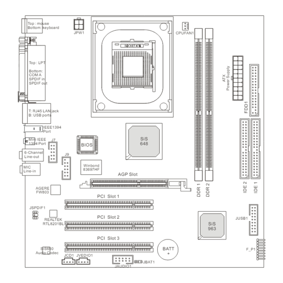
Page 4: Mainboard Layout
Mini IEEE 1394 Port BIOS 6-Channel Line-out Winbond 83697HF Line-in AGP Slot AGERE FW803 PCI Slot 1 JSPDIF1 PCI Slot 2 JUSB1 REALTEK RTL8201BL PCI Slot 3 SiS650 BATT F_P1 Audio Codec JCD1 JVEDIO1 JBAT1 JAUDIO1 MS-6701 v1.X M-ATX Mainboard... -
Page 5: Chapter 2. Hardware
Hardware Setup Chapter 2. Hardware Setup Hardware Setup This chapter tells you how to install the CPU, memory modules, and expansion cards, as well as how to setup the jump- ers on the mainboard. Also, it provides the instructions on con- necting the peripheral devices, such as the mouse, keyboard, etc. -
Page 6: Quick Components Guide
MS-6701 M-ATX Mainboard Quick Components Guide JPW1, p.2-9 CPU, p.2-3 CPUFAN1, p.2-17 DDR DIMMs, p.2-7 CONN1, p.2-9 Back Panel FDD1, p.2-15 I/O, p.2-10 J7, p.2-26 IDE1 & IDE2 p.2-16 J9, p.2-26 AGP Slot, p.2-28 JSPDIF1, p.2-23 JUSB1, p.2-27 F_P1, p.2-17 JCD1, p.2-25 PCI Slots, p.2-28 JBAT1, p.2-25... -
Page 7: Central Processing Unit (Cpu)
Hardware Setup Central Processing Unit: CPU ® ® The mainboard supports Intel Pentium 4 processor in the 478 pin package. The mainboard uses a CPU socket called PGA478 for easy CPU installation. When you are installing the CPU, make sure the CPU has a heat sink and a cooling fan attached on the top to prevent overheating. -
Page 8: Cpu Installation Procedures For Socket 478
MS-6701 M-ATX Mainboard CPU Installation Procedures for Socket 478 Please turn off the power and unplug the power cord before Open Lever installing the CPU. Pull the lever sideways away Sliding 90 degree Plate from the socket. Make sure to raise the lever up to a 90- degree angle. -
Page 9: Installing The Cpu Fan
Hardware Setup Installing the CPU Fan As processor technology pushes to faster speeds and higher performance, thermal management becomes increasingly important. To dissipate heat, you need to attach the CPU cooling fan and heatsink on top of the CPU. Follow the instructions below to install the Heatsink/Fan: Locate the CPU and its retention Position the heatsink onto the reten-... - Page 10 MS-6701 M-ATX Mainboard Connect the fan power cable from the mounted fan to the 3-pin fan power connector on the board. fan power cable NOTES...
- Page 11 Hardware Setup Memory The mainboard provides 2 slots for 184-pin DDR SDRAM DIMM (Double In-Line Memory Module) modules and supports the memory size up to 2GB. You can install DDR200/266/333 modules on the DDR DIMM slots (DIMM 1~2). DDR DIMM Slots (DDR 1~2)
-
Page 12: Dimm Module Combination
MS-6701 M-ATX Mainboard DIMM Module Combination Install at least one DIMM module on the slots. You can install either single- or double-sided modules in any order to meet your own needs. Memory modules can be installed in any combination as follows: Slot Memory Module Total Memory... -
Page 13: Power Supply
Hardware Setup Power Supply The mainboard supports ATX power supply for the power system. Be- fore inserting the power supply connector, always make sure that all compo- nents are installed properly to ensure that no damage will be caused. ATX 20-Pin Power Connector: CONN1 This connector allows you to connect to an ATX power supply. -
Page 14: Back Panel
MS-6701 M-ATX Mainboard Back Panel The back panel provides the following connectors: 6 Channel L-out Parallel (Optional) Mouse L-in IEEE1394 Keyboard SPDIF- SPDIF- COM A Ports Mouse Connector The mainboard provides a standard PS/2 ® mouse mini DIN connector ® ®... -
Page 15: Keyboard Connector
Hardware Setup Keyboard Connector ® The mainboard provides a standard PS/2 keyboard mini DIN connec- ® ® tor for attaching a PS/2 keyboard. You can plug a PS/2 keyboard directly into this connector. Pin Definition SIGNAL DESCRIPTION Keyboard DATA Keyboard DATA No connection Ground Keyboard Clock... -
Page 16: Parallel Port Connector: Lpt1
MS-6701 M-ATX Mainboard Parallel Port Connector: LPT1 The mainboard provides a 25-pin female centronic connector as LPT. A parallel port is a standard printer port that supports Enhanced Parallel Port (EPP) and Extended Capabilities Parallel Port (ECP) mode. Pin Definition SIGNAL DESCRIPTION STROBE... -
Page 17: Lan Jack (Optional)
Hardware Setup RJ-45 LAN Jack (Optional) The mainboard provides a RJ-45 connector that allows your computer to be connected to a network environment. Signal Description Transmit differential pair Transmit differential pair Receive differential pair Not used Not used Receive differential pair LAN Jack Not used (RJ-45) - Page 18 MS-6701 M-ATX Mainboard IEEE1394 Ports The mainboard provides two IEEE 1394 ports. The mini IEEE1394 port is designed for you to connect the IEEE1394 device with external power. The standard IEEE1394 port connects to IEEE1394 devices without external power. The IEEE1394 high-speed serial bus complements USB by providing enhanced PC connectivity for a wide range of devices, including consumer electronics audio/video (A/V) appliances, storage peripherals, other PCs, and portable devices.
-
Page 19: Serial Port Connector: Com A
Hardware Setup Serial Port Connector: COM A The mainboard offers one 9-pin male DIN connector as serial port COM A. The port is a 16550A high speed communication port that sends/receives 16 bytes FIFOs. You can attach a serial mouse or other serial devices directly to the connector. -
Page 20: Floppy Disk Drive Connector: Fdd1
MS-6701 M-ATX Mainboard Connectors The mainboard provides connectors to connect to FDD, IDE HDD, case, modem, LAN, USB Ports, IR module and CPU/System FAN. Floppy Disk Drive Connector: FDD1 The mainboard provides a standard floppy disk drive connector that supports 360K, 720K, 1.2M, 1.44M and 2.88M floppy disk types. FDD1 2-16... -
Page 21: Hard Disk Connectors: Ide1 & Ide2
Hardware Setup Hard Disk Connectors: IDE1 & IDE2 The mainboard has a 32-bit Enhanced PCI IDE and Ultra DMA 33/66/ 100/133 controller that provides PIO mode 0~4, Bus Master, and Ultra DMA 33/66/100/133 function. You can connect up to four hard disk drives, CD- ROM, 120MB Floppy (reserved for future BIOS) and other devices. -
Page 22: Fan Power Connector: Cpufan1
MS-6701 M-ATX Mainboard Fan Power Connector: CPUFAN1 The CPUFAN1 (processor fan) supports system cooling fan with +12V. It supports a three-pin head connector. When connecting the wire to the connector, always take note that the red wire is the positive and should be connected to the +12V, the black wire is Ground and should be connected to GND. - Page 23 Hardware Setup Front Panel Connector: F_P1 The mainboard provides one front panel connector for electrical con- nection to the front panel switches and LEDs. PS-ON PWR_LED HDD_LED Reset F_P1 2-19...
-
Page 24: Front Panel Audio Connector: Jaudio1
MS-6701 M-ATX Mainboard Front Panel Audio Connector: JAUDIO1 The JAUDIO1 front panel audio connector allows you to connect to the ® front panel audio and is compliant with Intel Front Panel I/O Connectivity Design Guide. JAUDIO1 JAUDIO1 Pin Definition Description Description Speaker_R Front_R... -
Page 25: Front Usb Connector: Jusb1
Hardware Setup Front USB Connector: JUSB1 The mainboard provides one front Universal Serial Bus connector for users to connect USB devices. JUSB1 JUSB1 Pin Definition Description Description Power Power SGND SGND Power Power 2-21... -
Page 26: Cd-In Connector: Jcd1
MS-6701 M-ATX Mainboard CD-In Connector: JCD1 The connector is for CD-ROM audio connector. Audio Connector: JVEDIO1 This connector allows you to connect to a TV Tuner Card. JCD1 JVEDIO1 VIDEO-L VIDEO-R 2-22... -
Page 27: Spdif Connector: Jspdif1
Hardware Setup SPDIF Connector: JSPDIF1 The connector is used to connect an optional bracket for SPDIF (Sony & Philips Digital Interconnect Format) digital audio transmission. JSPDIF1 JSPDIF1 Pin Definition Description Description VCC5 VCC3 SPDIF-O SPDIF-I 2-23... - Page 28 MS-6701 M-ATX Mainboard IEEE 1394 Connector: J7 (Optional) The mainboard provides one IEEE1394 connector with housing that allows you to connect optional IEEE 1394 ports. Pin Definition SIGNAL SIGNAL IEGND TPA0- TPA0+ Power Power TPB0+ TPB0- IEGND 2-24...
- Page 29 Hardware Setup Joystick/Game Connector: J9 (Optional) You can connect a joystick or game pad to this connector. J9 Pin Definition Description Description FVCC5 (power) Key pin 2-25...
-
Page 30: Clear Cmos Jumper: Jbat1
MS-6701 M-ATX Mainboard Jumpers The motherboard provides the following jumpers for you to set the computer’s function. This section will explain how to change your motherboard’s function through the use of jumpers. Clear CMOS Jumper: JBAT1 There is a CMOS RAM on board that has a power supply from external battery to keep the data of system configuration. -
Page 31: Agp (Accelerated Graphics Port) Slot
Hardware Setup Slots The motherboard provides one AGP slot and three 32-bit PCI bus slots. AGP Slot PCI Slots AGP (Accelerated Graphics Port) Slot The AGP slot allows you to insert the AGP graphics card. AGP is an interface specification designed for the throughput demands of 3D graphics. It introduces a 66MHz, 32-bit channel for the graphics controller to directly access main memory. -
Page 32: Pci Interrupt Request Routing
MS-6701 M-ATX Mainboard PCI Interrupt Request Routing The IRQ, acronym of interrupt request line and pronounced I-R-Q, are hardware lines over which devices can send interrupt signals to the microprocessor. The PCI IRQ pins are typically connected to the PCI bus INT A# ~ INT D# pins as follows: Order 1 Order 2...
Need help?
Do you have a question about the MS-6701 v1.X M-ATX and is the answer not in the manual?
Questions and answers