Table of Contents
Advertisement
6670 185th AVE NE
Redmond, WA 98052
O p e r a t i o n s G u i d e
M i c r o s e t ™ I I
Contents
Quick Reference ..........................................................................3
Introduction..................................................................................4
Mounting.......................................................................................5
Wiring............................................................................................8
Compatibility with Earlier Version VLCs ...................................8
Operational Overview..................................................................9
Operating Mode Specifics.........................................................12
Field Service Mode ....................................................................24
Balance Mode.............................................................................25
VLC DDC BV and AV Assignments..........................................26
USA
Voice:425.869.8400
Fax:425.869.8445
I n s t a l l a t i o n &
Document ID:
Specifications........................................................................4
VLC Versions Prior to 1.06c..................................................8
VLC Versions 1.06c through 1.08 .........................................8
Hotel vs. Office Modes..........................................................9
Fan-control vs. No-fan-control Modes...................................9
Cooling and Heating Setpoint Calculation.............................9
Occupied Setpoint Logic (BV-67 ON)...........................9
Unoccupied Setpoint Logic (BV-67 OFF) .....................9
After-hours Override Operation...........................................10
Housekeeping Override Operation......................................10
English and Metric Units .....................................................10
Outside Air Temperature (OAT) Display .............................10
LCD Backlight Operation.....................................................10
Testing the LCD ..................................................................11
DDC for Enabling Operating Modes....................................13
Office Modes.......................................................................14
M1-Office, No Fan, Occupied ..................................14
M2-Office, No Fan, Unoccupied...............................15
M3-Office, No Fan, Occupied, ON/OFF...................16
M4-Office, Fan, Occupied........................................17
M5-Office, Fan, Unoccupied......................................18
Hotel Modes........................................................................20
M6-Hotel, No Fan, Rented.......................................20
M7-Hotel, No Fan, Vacant .......................................21
M8-Hotel, Fan, Rented.............................................22
M9-Hotel, Fan, Vacant.............................................23
e-mail:info@alerton.com
LTBT-TM-MSET2
www.alerton.com
Advertisement
Table of Contents

Related Manuals for ALERTON BACtalk Microset II

Summary of Contents for ALERTON BACtalk Microset II
-
Page 1: Table Of Contents
Hotel Modes................20 M6—Hotel, No Fan, Rented........20 M7—Hotel, No Fan, Vacant ........21 M8—Hotel, Fan, Rented..........22 M9—Hotel, Fan, Vacant..........23 Field Service Mode ..............24 Balance Mode................25 VLC DDC BV and AV Assignments..........26 6670 185th AVE NE Redmond, WA 98052 Voice:425.869.8400 Fax:425.869.8445 e-mail:info@alerton.com www.alerton.com... - Page 2 © 1999 - 2011 Honeywell. All Rights Reserved. 6670 185th AVE NE Redmond, WA 98052 USA Phone: (425)869-8400 FAX: (425)869-8445 Web Site: www.alerton.com Rev. 0003 LTBT-TM-MSET2...
-
Page 3: Quick Reference
Quick Reference Display/control function Description Software remarks • Setpoint (°F or °C as appropriate) Displays unit setpoint, after-hours/ • Setpoint = AV-90. • Override time remaining housekeeping timer, ON/OFF status, or • Housekeeping timer or after-hours timer = • ON/OFF status value of field service code, depending on AV-98. -
Page 4: Introduction
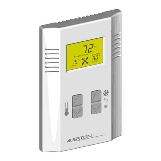
VLC that are reserved for Microset operation. English or metric units These data points are available from the VLC as BACnet objects. 1. The Microset II is not compatible with the Alerton TUX product line. Specifications Table 1 BACtalk Microset II specifications. Thermistor The thermistor is integrated with the device. -
Page 5: Mounting
Mounting Mounting The Microset II is designed to be wall-mounted indoors, with dimensions ideal for mounting to a single-gang electrical box. See Fig. 3 on p. 6. Mount in a clean, dry location away from windows, air ducts, and other places where environmental factors may affect temperature and humidity readings. - Page 6 M i c r o se t ™ I I —I n s t a l l a t i o n and Operations Guide Secure the backplate to the mounting surface with the To secure the Microset II to a mounting surface: enclosed screws or your own.
- Page 7 Mounting Gently pull the freed corner of the Microset II away To remove the Microset II from the backplate: from the wall. Insert a thin, flat-tipped screwdriver into the last vent Repeat steps 1–4 on the other side. slot on the bottom of the Microset. Position the screwdriver so that you can apply pressure to the Push upward on the bottom of the Microset II until it is backplate leg (see Fig.
-
Page 8: Wiring
Table 7 on p. 26). The Microset II may be used in fan-control applications by cutting a circuit board trace on the Microset II (contact your Alerton Representative or Alerton Technical Support). If the trace is cut, BV-65 selects office mode or hotel Fig. -
Page 9: Operational Overview
O p e r a t i o n a l O v e r vi e w Operational In no-fan-control modes, the occupant is unable to select fan speed. However, if desired, VLC DDC can cause fan symbology to display at the Microset II. No-fan-control modes Overview are typically used in VAV or heat pump applications. -
Page 10: After-Hours Override Operation
M i c r o se t ™ I I —I n s t a l l a t i o n and Operations Guide After-hours Override English and Metric Operation Units Unoccupied office modes (M2 and M5) offer an after-hours You can set the Microset II to display English or metric units override feature, which enables the occupant to override a based on the selection in the VLC DDC header file or you can... -
Page 11: Testing The Lcd
O p e r a t i o n a l O v e r vi e w Testing the LCD You can test the LCD to ensure that it is functional. To test the LCD: Press and hold the left and right buttons DOWN... -
Page 12: Operating Mode Specifics
M i c r o se t ™ I I —I n s t a l l a t i o n and Operations Guide Operating Mode Use Table 4 on p. 13 to determine DDC values to set for enabling each operating mode. -
Page 13: Ddc For Enabling Operating Modes
Operating Mode Specifics DDC for Enabling Table 4 lists data point settings for the various operating modes and indicates the action of BV-67 in each mode. See Table 7 on p. 26 for further detail. Operating Modes Combinations of values for BVs 64, 65, 80, and 81 in VLC DDC control operating modes. -
Page 14: Office Modes
M i c r o se t ™ I I —I n s t a l l a t i o n and Operations Guide Office Modes This mode’s counterpart is M2, which is activated by setting BV-64 OFF. Office modes are typically used in commercial use Indicates that setpoint is displayed. -
Page 15: M2-Office, No Fan, Unoccupied
Operating Mode Specifics M2—Office, No Fan, After-hours Override Operation When after-hours override is in effect, the after-hours timer Unoccupied (AV-98) automatically decrements, and the LCD displays the current timer value. The unit controls to occupied setpoints while the after-hours timer is non-zero. Set BVs 64, 65, 80, and 81 OFF. -
Page 16: M3-Office, No Fan, Occupied, On/Off
M i c r o se t ™ I I —I n s t a l l a t i o n and Operations Guide M3—Office, No Fan, Operation when OFF The LCD displays the word OFF. The unit controls to Occupied, ON/OFF unoccupied setpoints. -
Page 17: M4-Office, Fan, Occupied
Operating Mode Specifics M4—Office, Fan, Operation with Fan OFF If the occupant presses the right button until the fan DOWN Occupied turns OFF, the fan symbol stops turning, the fan speed bars are not visible, and the word OFF appears on the LCD. The unit Set BVs 64 and 80 ON and BV-81 OFF. -
Page 18: M5-Office, Fan, Unoccupied
M i c r o se t ™ I I —I n s t a l l a t i o n and Operations Guide M5–Office, Fan, The occupant can increase or decrease the timer to the next half-hour increment up to the timer limit (AV-97) with the right buttons. - Page 19 Operating Mode Specifics Fan Speed Mode Setpoint Adjustment Mode Pressing either left button when the unit is in after-hours override causes the setpoint to display. The occupant can use the left buttons to adjust the setpoint. DOWN Fan status reflects occupant-selected fan The setpoint remains speed...
-
Page 20: Hotel Modes
M i c r o se t ™ I I —I n s t a l l a t i o n and Operations Guide Hotel Modes Operation when OFF The LCD displays the word OFF. The unit controls to Hotel modes have a feature set typically used in the hospitality unoccupied setpoints. -
Page 21: M7-Hotel, No Fan, Vacant
Operating Mode Specifics M7—Hotel, No Fan, Housekeeping Override Operation The LCD displays the override time remaining. The unit Vacant controls to occupied setpoints while the override timer (AV-98) is non-zero. Set BV-81 ON and BV-64 and BV-80 OFF. The unit controls to Housekeeping can press the right button to cancel the DOWN... -
Page 22: M8-Hotel, Fan, Rented
M i c r o se t ™ I I —I n s t a l l a t i o n and Operations Guide M8—Hotel, Fan, Rented Operation with Fan OFF If the tenant presses the right button until the fan turns DOWN Set BVs 64, 80, and 81 ON. -
Page 23: M9-Hotel, Fan, Vacant
Operating Mode Specifics M9—Hotel, Fan, Vacant Housekeeping Override Operation Set BV-64 OFF and BV-80 and BV-81 ON. The display is blank. The unit controls to unoccupied heating and cooling The LCD displays the override time remaining. The unit setpoints. controls to occupied setpoints while the override timer (AV-98) is non-zero. -
Page 24: Field Service Mode
M i c r o se t ™ I I —I n s t a l l a t i o n and Operations Guide Use the left buttons to set the lower right DOWN Field Service display item to the number 7. Press the right button. -
Page 25: Balance Mode
Balance Mode Repeat step 1. Table 5 Field service mode fixed codes. Press the right button. Code Data point Meaning Use the left buttons to set the lower right AV-95 Unoccupied cooling setpoint DOWN display item to the number 96. AV-96 Unoccupied heating setpoint Press the right... -
Page 26: Vlc Ddc Bv And Av Assignments
M i c r o se t ™ I I —I n s t a l l a t i o n and Operations Guide VLC DDC BV available from the VLC as BACnet objects; BACnet-compliant devices can access the properties of these objects. For a complete reference of objects and properties available in and AV VLCs, see the Programmer’s Guide and Reference for BACtalk... - Page 27 VLC DDC BV and AV Assignments Table 7 VLC DDC BV assignments for the Microset II. (Continued) Read Data point only Description ON action/status OFF action/status LCD backlight command. See “LCD Backlight LCD backlight ON continuously. LCD backlight is ON only in BV-79 Operation”...
- Page 28 M i c r o se t ™ I I —I n s t a l l a t i o n and Operations Guide Table 8 VLC DDC AV assignments for the Microset II. (Continued) Data point Read only Description AV-105 Not used in Microset II.
- Page 29 Notes LTBT-TM-MSET2...
- Page 30 Notes LTBT-TM-MSET2...
- Page 31 Notes LTBT-TM-MSET2...
- Page 32 6670 185th AVE NE Redmond, WA 98052 425.869.8400 Fax:425.869.8445 www.alerton.com...
Need help?
Do you have a question about the BACtalk Microset II and is the answer not in the manual?
Questions and answers